Week 13
Apr 26: Networking and communications
List of task this week
Group assignment
To see the group assignment go here.
My thoughts on this week's group assignment, send a message between two projects: this really helped me be confident in my ability to use networking, I had no problem adding Andri’s node in the code and it worked so well.Design, build, and connect wired or wireless node(s) with network or bus addresses
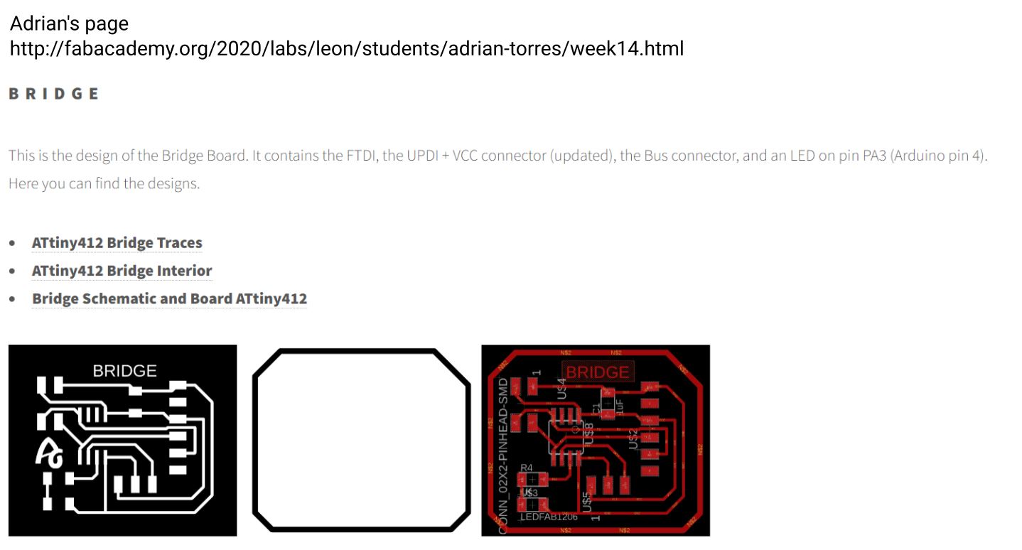
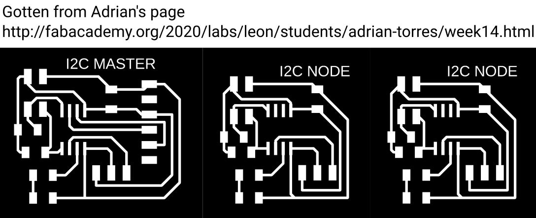
I took inspiration from Adrian’s page, he has done some good work and documented it well. Adrian had made a bridge and nodes and my plan was to draw up similar boards except have buzzers on the nodes instead of lights, going through this week you will see that that plan did not work but my second attempt did.
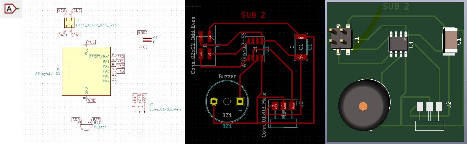
Like in previous weeks I drew the bords up in Kicad but instead of connecting with the lines I used the Place global label tool, it turns out I find that much more comfortable to use. I like to use Dom and Sub instead of the old lingo so keep that in mind while reading the rest.
I exported the board drawings to .svg, inverted it in Inkscape and exported to .png.
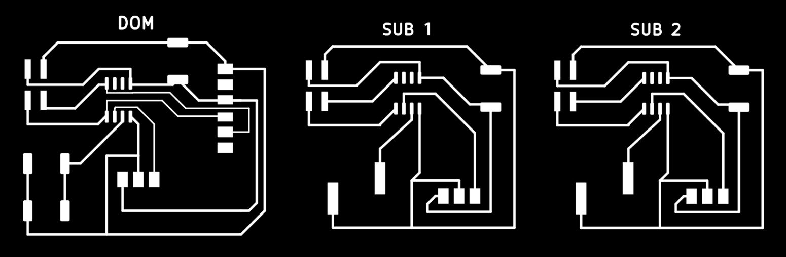
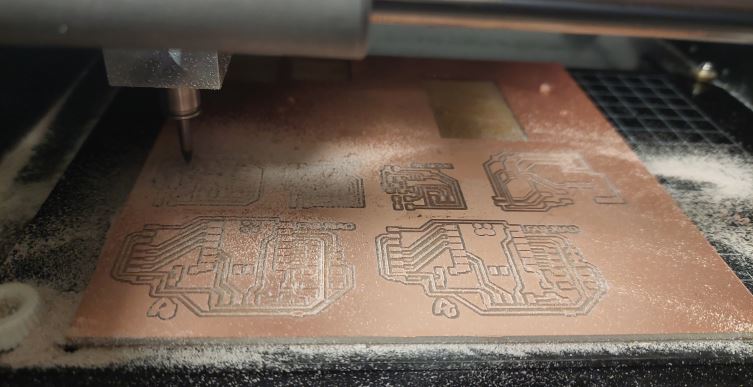
I decided to mill the boards out all at once and it went perfectly. To see how I mill out see the group page week 8.
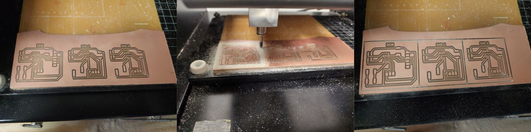
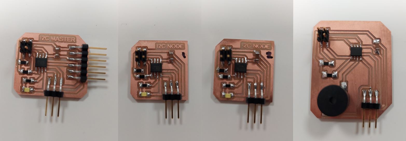
As you can see on the picture below, I chose the wrong foot print for the capacitors, resistors and the led, so there was too much space between each side. I was able to make this work by taking a knife and scraping the coper of between away and putting a little cut of a bare wire between to fill the gap and shoulder it all connected.
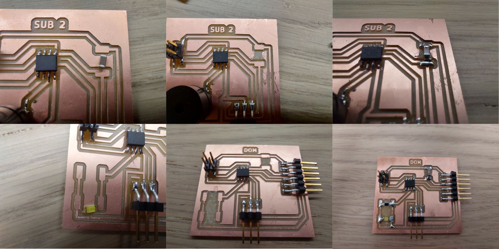
I finished soldering everything on and put a ribbon wire to connect all three, I used the bridge and node code from Adrian’s page and changed the led part to a buzzer code that I got here, but it did not work, I tried to use the I2C code further down on Adrian’s page but it would only work for the one I had received the number 1, found out later that that code was only sending the number one so this might have worked if I had noticed that right away but I did not so I scraped this project.
I decided to make Adrian’s Hello I2C with ATtiny 412 and get that to work and then making a third node that I design myself to add to it. So I took the design from Adrian’s page and got that ready in Inkscape.
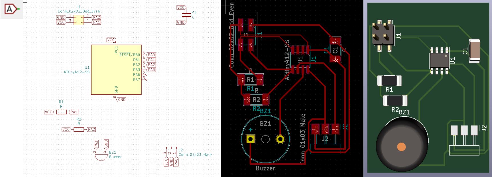
I was going to a Fab Lab Iceland bootcamp so I designed the third node and milled it out with the others to take with me to the bootcamp. I used Kicad to design the third node and used my earlier design just added 2 resistors because that’s how it is on Adrian’s boards because this is a I2C design and that needs to have those resistors.
I milled out those four boards, on the picture you can see two other boards that are also Adrian’s design but those were just for the bootcamp. To see how I mill out see the group page week 8.
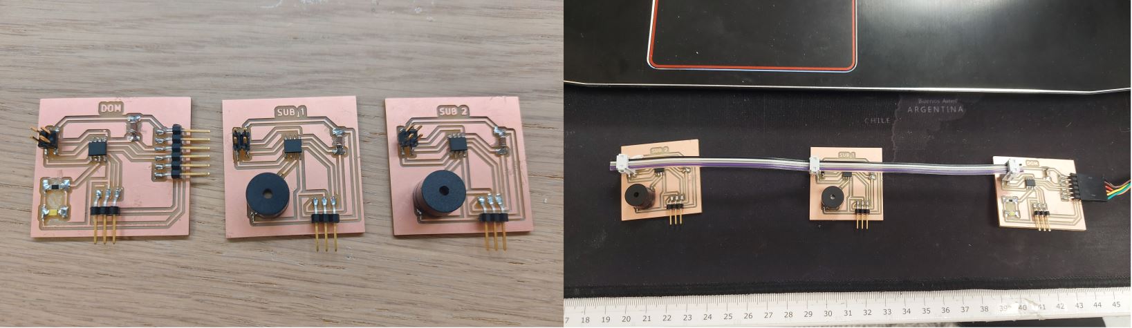
I soldered everything on and drew a 1 and 2 on the identical nodes so I would not get them confused. I checked all the connections with a multi meter and everything looked good.
I made a new ribbon wire with 4 attachments, I clipped them on to see if everything fit.
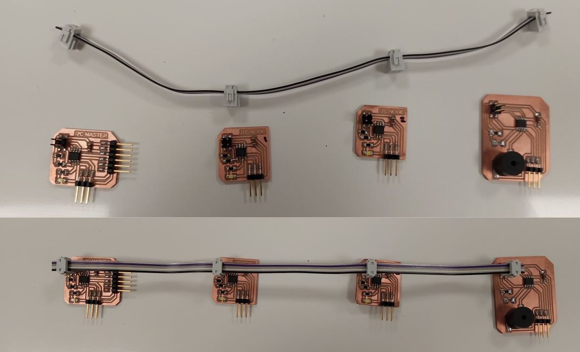
To start with I connected just the 3 that are strait from Adrian’s page and used his code as is and like expected it worked.
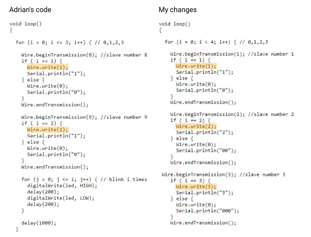
When I was adding the third node, the one I designed I had some troubles and the node would not buzz, after putting my head in the water I saw that the Wire.write was 1 on both the nodes so I changed that too 1,2 and 3 and changed the Serial.println as well.
After that every thing went like a dream and like you can see in the video I was ecstatic.