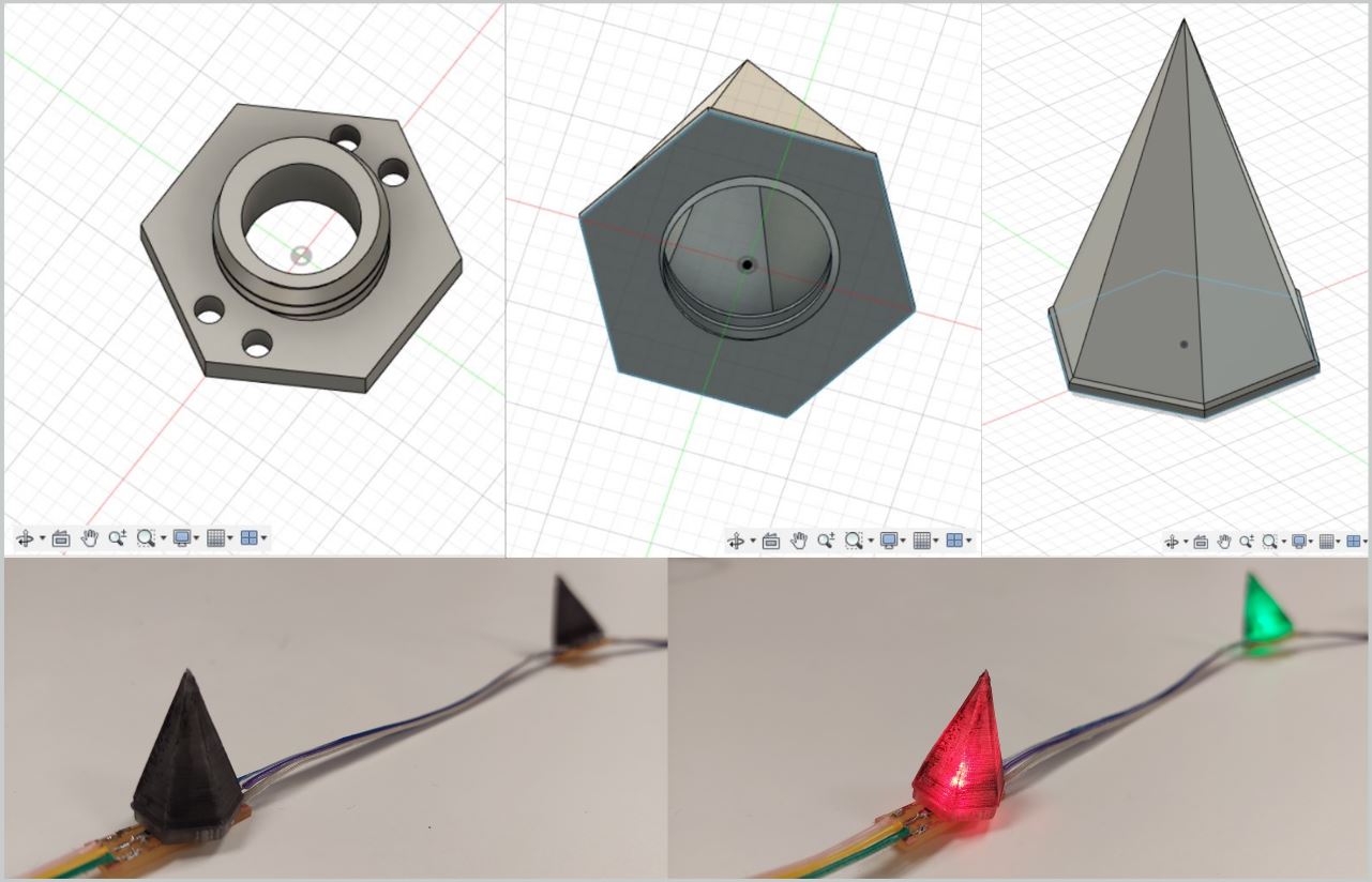
Holow screw on spikes for final project
List of task this week
- Model (raster, vector, 2D, 3D, render, animate, simulate, ...) a possible final project
-
Compress your images and videos
-
Post a description with your design files on your class page
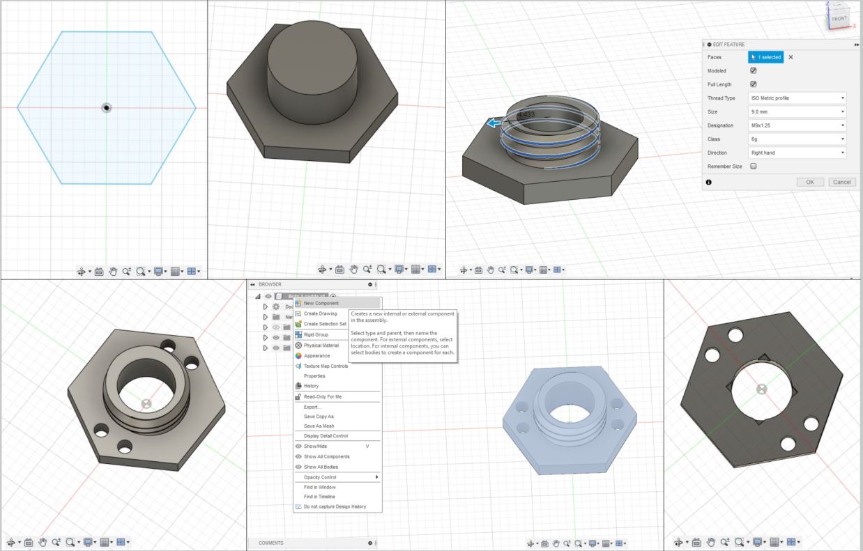
Bottom of spike modeled in Fusion 360
My knowledge of fusion 360 is pretty limited I have really only done one project in it before,
but my coworkers use it allot so I decided that it would be my pick for 3D modeling.
I used the Create Sketch tool and picked the “floor” phase, I used the Polygon and made it a 6
corner one so it would be a hexagon and made it 16.166mm on the wide side. I right clicked on the
hexagon and selected push/pull and pulled it up 2mm. Sketched a circle on top of the hexagon and
made it a diameter of 8.485mm and pulled it up 3mm. I sketched another circle on top of the last
one but made that one a diameter of 6mm down to the bottom to make a hole through. To put threading
on the cylinder and made sure to take a screenshot of the settings there so I would have them later
when I make the top. I made the threading by going to create and selecting thread and selecting the
cylinder part and pulled it in 4.433. I made little circles on the hexagon and pulled down to make
holes. At the end I sketched a center rectangle on the bottom and pulled 1.5mm up to make space for
the led. A coworker pointed out that I should make different components for different parts, so I made
it so the bottom was one component and put the spike in a separate component.
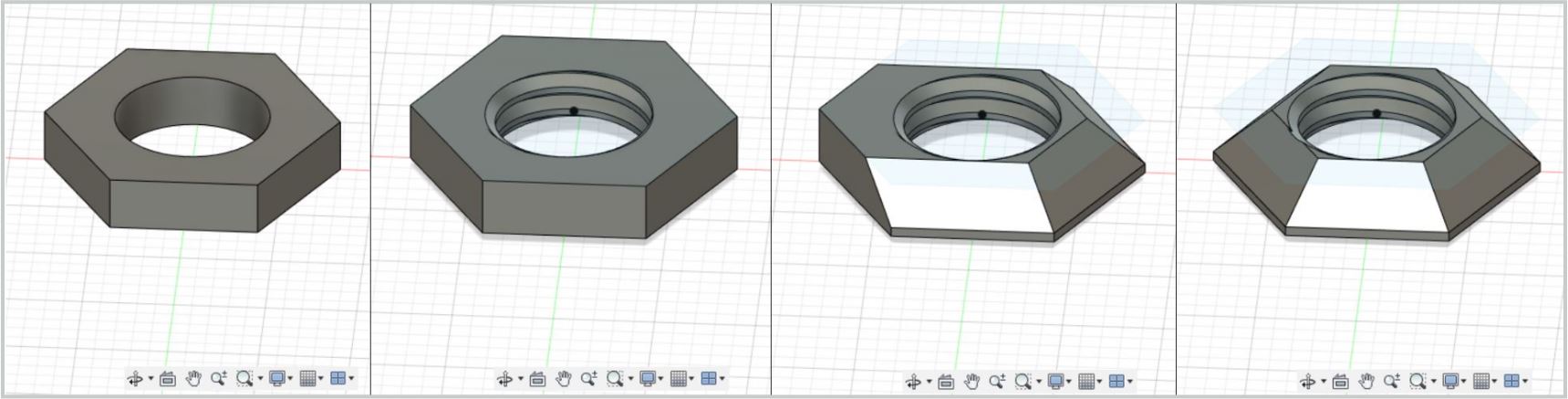
Holow spike modeled in Fusion 360, screw part
I tried to make the spike all in one go but was not successful, I realized that the roof tool fills even if you
have two walls so I did the screw part separate and then the hollow spike separate.
So, after my first attempt failed I started with the screw part first. I went in to sketch and made a hexagon,
pulled up just like described above. I sketched a circle and pulled down. Put threading on the inner cylinder and
made sure to take a look at the screenshot of the settings and make them the same. I didn’t want there to be a base
and then a spike so I used the chamfer tool to adjust the sides so when I put the spike on it would not be in the way.
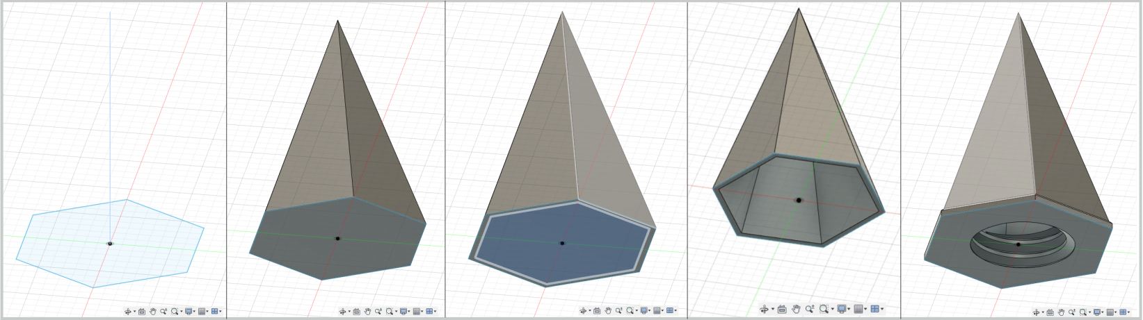
Holow spike modeled in Fusion 360, spike part
To make the spike I went in to sketch and made a hexagon and a line from the middle of the hexagon to 21mm height, selected
both went into create and used the tool loft. Made another one the same way only a little smaller to take out of the bigger
one to make 0.5mm thick walls.
Having both parts of the spike I used the tool combine
Trying Gimp to editing images
I used to just use Inkscape to get photographs ready to raster in the laser but a colleague of mine
always uses Gimp so I decided to try that.
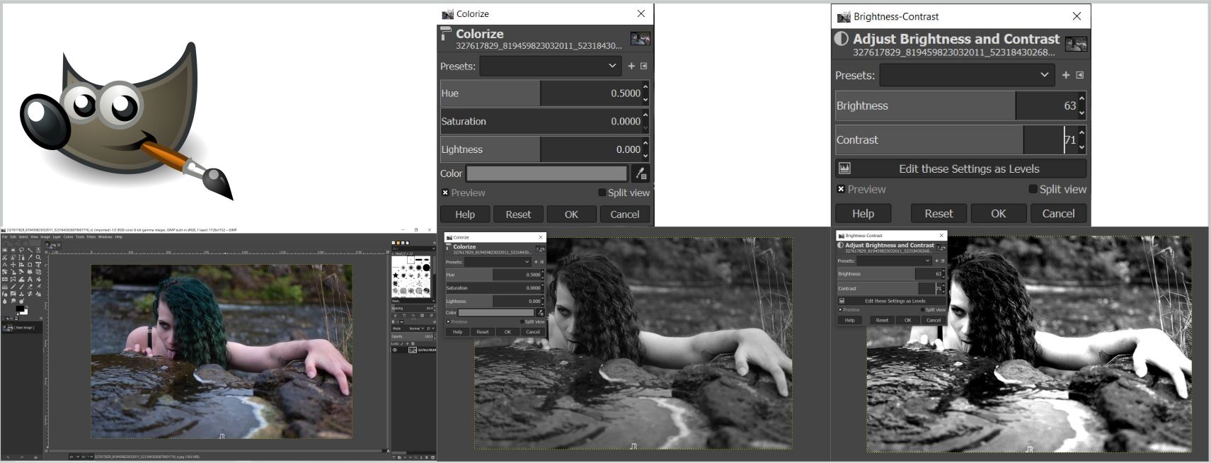
I opened Gimp and dragged in an image. I went into Colors and selected Colorize and took the
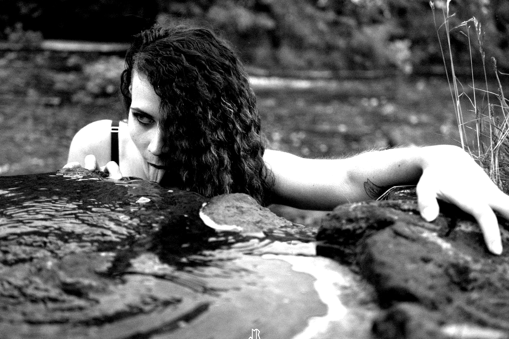
saturation down to 0 to make the image black and white. I went into colors and selected Brightness-contrast,
there I changed the brightness and contrast until I thought It was extreme enough to raster onto wood.
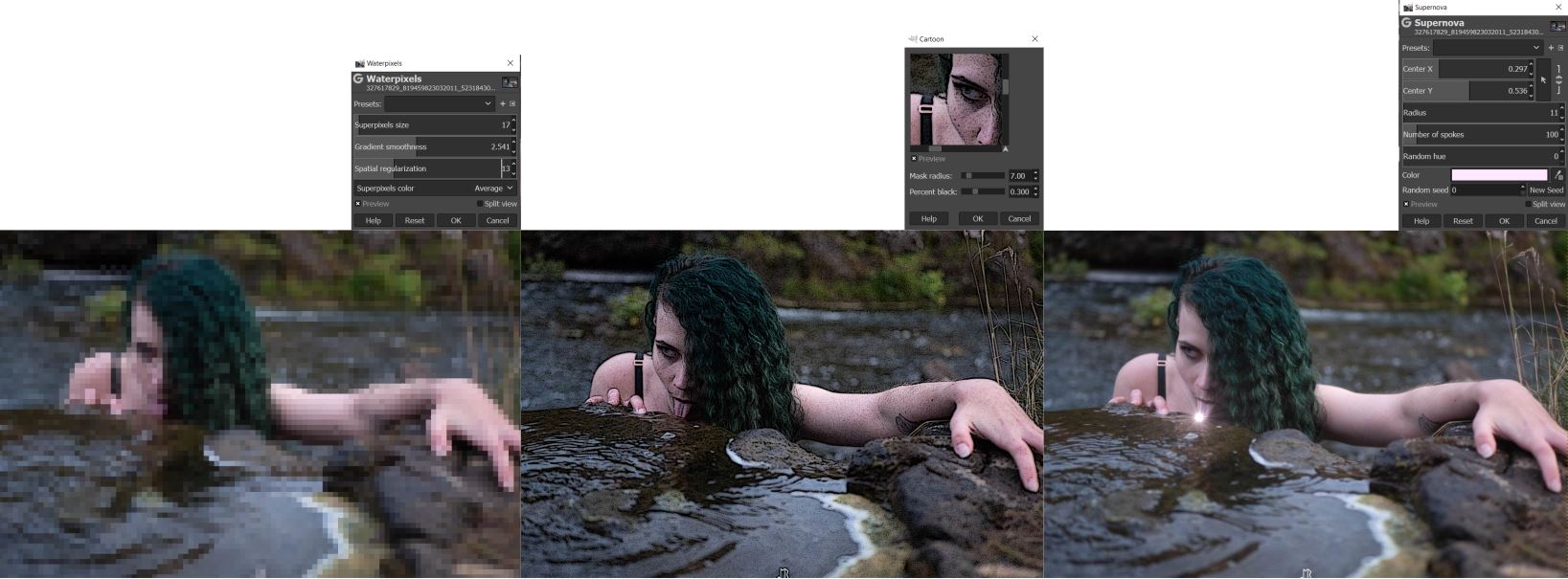
To do a little more I played with the filters to get a feeling for that, here are some of my favorites.