11. Input devices
1.1 Assignments of the Week
- Group assignment:
- Probe an input device(s)'s analog and digital signals
- Document your work on the group work page and reflect on your individual page what you learned
-
Individual assignments:
- Measure something: add a sensor to a microcontroller board that you have designed and read it.
1.2 Group Assignment
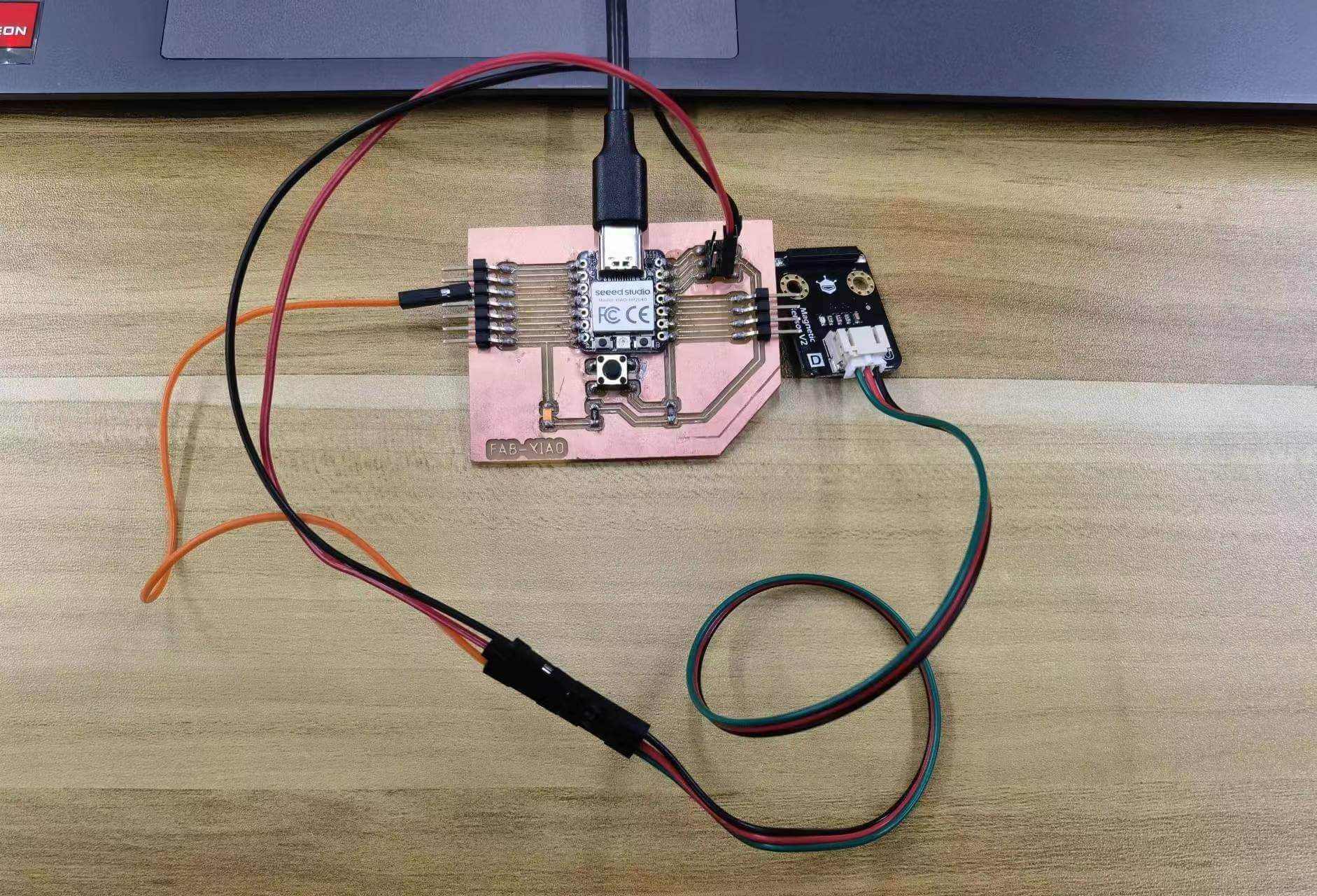
We used a multimeter to probe the digital signal of the magnetic senser. (Wiring and the code of the magnetic sensor is in the individual assignment down below.) We tested the difference in the voltage delivered to the development board when the magnetic sensor detects a magnet and when it does not detect a magnet.
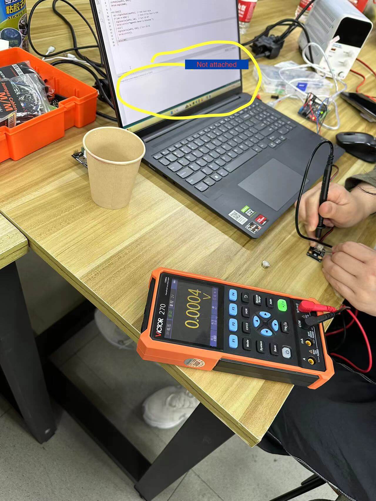
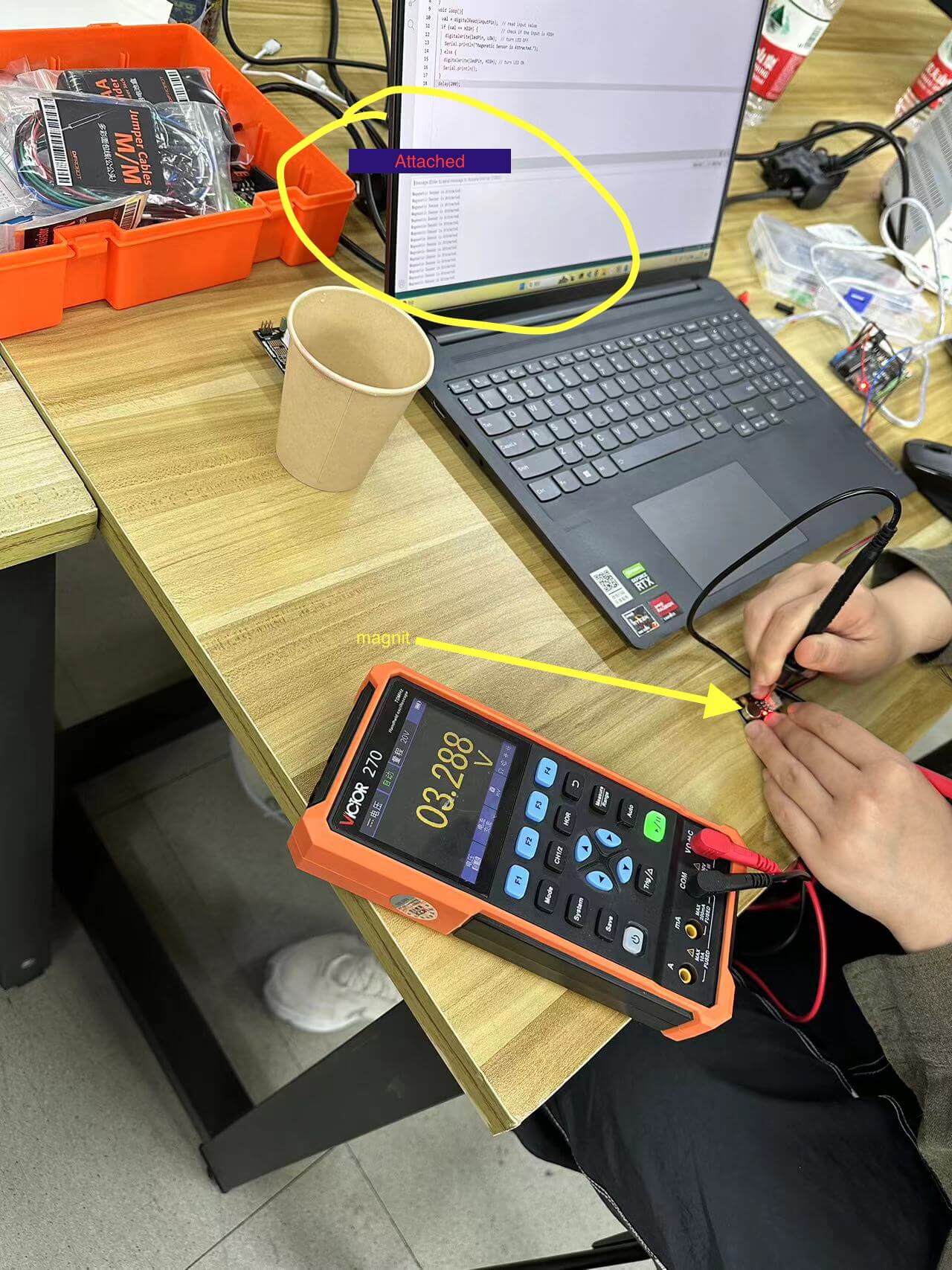
- When there was no magnet attached, the voltage was close to
0vwhich the arduino would read as aLOWsignal (shown in the left picture). - When we put a little maget there, the voltage increased to around
3.3Vwhich the arduino would read as aHIGHsignal (shown in the right picture).
1.3 Individual Assignment
1.3.1 Digital Magnetic Sensor
Magnetic sensors based on magnetically sensitive materials can be used to detect magnetic materials (magnets). The detection range can reach about 3cm (the detection range is related to the strength of the magnetism).
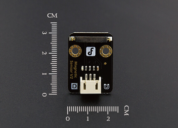
Specificatons:
Pins:
More imformation: "Gravity: Digital Magnetic Sensor" by DFRobot
Wiring:
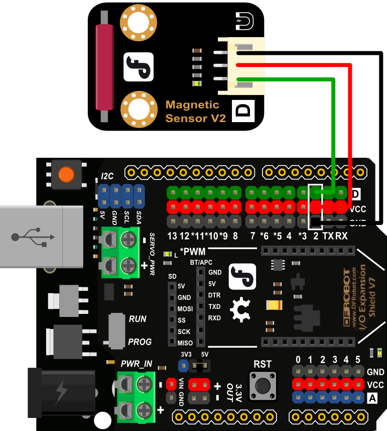
Coding:
I made a modification on the basis of the sample code on the official website. When the sensor detects a magnetic materials, it will display: "Magenetic Sensor is Attracted." in the serial monitor, and light up the LED on the Fab-Xiao development board. Otherwise, the LED is off, and the serial port The monitor display nothing.
int inputPin = D2;               // choose the input pin
int val = 0;                    // variable for reading the pin status
void setup() {
  pinMode(inputPin, INPUT);
  pinMode(D6,OUTPUT);
  Serial.begin(9600);
}
void loop(){
  val = digitalRead(inputPin);  // read input value
  if (val == HIGH) {            // check if the input is HIGH
    Serial.println("Magenetic Sensor is Attracted."); // print message in the serial monitor
    digitalWrite(D6,HIGH);  // turn LED ON
  } else {
    Serial.println();  // print nothing in the serial monitor
    digitalWrite(D6,LOW);  // turn LED off
  }
  delay(200);
}
Video:
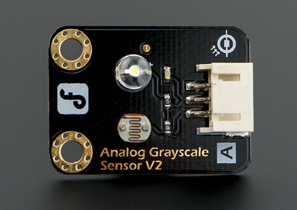
1.3.2 Analog Grayscale Sensor
The grayscale sensor is an analog sensor, used in combination with the special sensor expansion board for Arduino, it can sense the different colors of the ground or table and generate corresponding signals, which can realize interactive works related to colors, and can also be used as the line tracking sensor of the line tracking car Or the field grayscale recognition of football robots. The power supply needs to be consistent with the controller, usually 3.3V or 5V.
Specificatons:
Pins:
More imformation: "Gravity: Analog Grayscale Sensor" by DFRobot
Wiring:
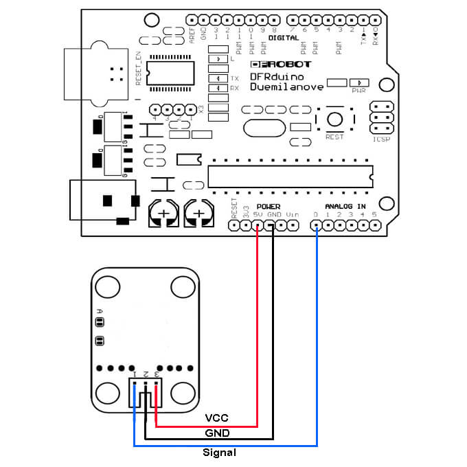
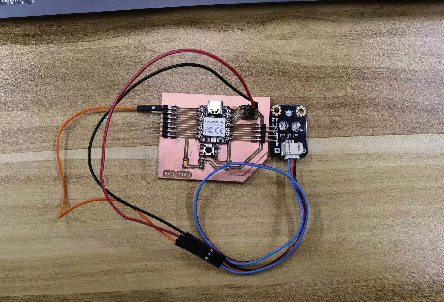
The operating voltage of the Seeed Studio XIAO RP2040 is 3.3V, so the VCC interface needs to be connected to the 3.3V power supply pin.
Coding:
I printed a grayscale step chart and used the sample code to measure different grayscale values.
        void setup()
        {
            Serial.begin(9600); // open serial port, set the baud rate to 9600 bps
        }
        void loop()
        {
            int val;
            val=analogRead(A0);   //connect grayscale sensor to Analog 0
            Serial.println(val,DEC);//print the value to serial
            delay(100);
        }
Video:
The video demonstrates that the sensor returns smaller values for brighter colors and larger values for darker colors. The grayscale image detected by the sensor ranges from white to black. Although the sensor theoretically returns an integer between 0 and 1023, the actual values are roughly between 90 and 900. I thought that this discrepancy may be due to poor performance in bright environments, so I turned off the light and tired again:
This time the value range returned is even smaller which confused me. So I checked out more about this sensor. This gray scale sensor is a composition of a photocell (light-controlled variable resistor) and a integrated white LED on board aiming just front of the sensor (see the schematic). It's connected LED will let you compare and provide some reflective feedback to analyse gray scale light ranges. Different colors will apply but only gray scale values will be outputted. This design cannot accurately measure the gray scale of the color. It's resonable to have this deviation.