6. Electronics design
I used to think this week would be tough, but it turns out not that difficult to draw a simple dev-board with some inputs and outputs after picking up my high school physics memories and learning EAGLE.
1.1 Assignments of the Week
- Group assignment:
- Use the test equipment in your lab to observe the operation of a microcontroller circuit board (as a minimum, you should demonstrate the use of a multimeter and oscilloscope)
- Document your work on the group work page and reflect what you learned on your individual page
-
Individual assignments:
- Design a development board to interact and communicate with an embedded microcontroller
1.2 Multimeter and Oscilloscope
Our test equipment is a multimeter and oscilloscope in one device.
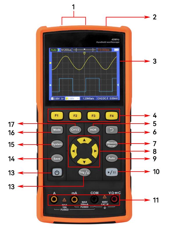
1. CH1, CH2 measured signal input connector.
2. Signal generator output connector (S type only).
3. Display area.
4. Press F1~F4 keys, multi-function keys, in each menu mode, press the corresponding key to select the corresponding menu item.
5. Press the HOR key, you can change the horizontal time base setting by pressing the key, and observe the resulting state information changes, and you can also find that the horizontal time base display corresponding to the status bar has changed accordingly; by pressing the key, you can adjust the signal in the waveform The horizontal displacement of the window.
6. Press the return key to return to the previous menu. When the menu is at the first level, press the return key again to close the menu.
7. Measurement menu key (oscilloscope) or range key (multimeter).
8. Zoom or move keys
9. Autoset button (oscilloscope) or autorange button (multimeter).
10. Stop/run button (oscilloscope) or hold button (multimeter) or output/close signal button (signal generator - S type only).
11. Multimeter input.
12. Trigger the menu key (oscilloscope) or the relative value key (multimeter).
13. Power switch button.
14. Enter the Save Settings button.
15. Enter the system setting button.
16. Button to switch the working status of oscilloscope and multimeter.
17. CH1/CH2 channel switching button.
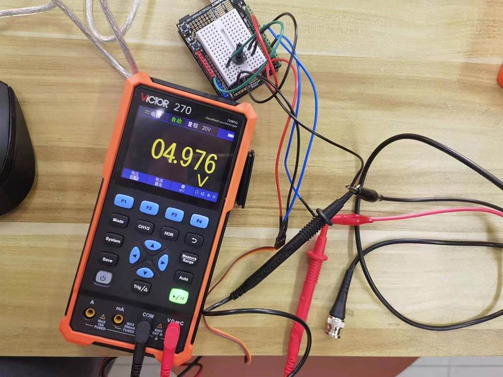
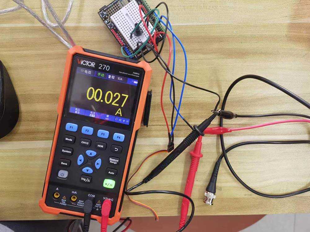
The Test :
We connected a potentiometer to the A0 pin of Arduino, a Micro Servo to the D9 pin, and the D5 pin is used to output the mapped analog signal. When we turn the potentiometer, we can observe the rotation of the servo, and detect the corresponding waveform, voltage, current and resistance through the D5 pin.
Here is the code. I made some modifications on dfrobot's source code.
          #include
          Servo myservo;

          int potpin = 0;
          int val_in;
          int val_servo;
          int val_out;
          int pin=5;

          void setup() {
                myservo.attach(9);
                pinMode(pin,OUTPUT);
          }

          void loop() {
                 val_in = analogRead(potpin);
                 val_servo = map(val_in, 0, 1023, 0, 179);
                 val_out=map(val_in,0,1023,0,255);
                 analogWrite(pin,val_out);
                 myservo.write(val_servo);
                 delay(15);
          }
1) Oscilloscope
Press the "Mode" to switch to the oscilloscope function. Connect positive to D5 pin, negative to GND. Then turn the potentiometer, you'll see the square wave on the screen.
A square wave is a non-sinusoidal periodic waveform in which the amplitude alternates at a steady frequency between fixed minimum and maximum values, with the same duration at minimum and maximum. In an ideal square wave, the transitions between minimum and maximum are instantaneous.
The square wave is a special case of a pulse wave which allows arbitrary durations at minimum and maximum amplitudes. The ratio of the high period to the total period of a pulse wave is called the duty cycle.
Square waves are often encountered in electronics and signal processing, particularly digital electronics and digital signal processing. Its stochastic counterpart is a two-state trajectory.
---- from Wikipedia
2) Multimeter
Press the "Mode" to switch to the multimeter function. Connect positive to D5 pin, negative to GND. Press F1~F4 to select the corresponding function.
1.3 Electronic Components
- Switch and Button: button is connected when pressed, and disconnected when you let go, which is different from switch.
- Capacitor: capacitor can store and release energy. It is used in a electronic circuit to suppress voltage spikes, clean a signal and as local energy storage.
- Diode: the main characteristic is unidirectional conductivity. It is often used to connect the DC Motor to prevent the motor from rotating in the opposite direction and generate reverse current.
- Transistor: the most important component of modernelectronics. They are used as a digital switch in a variety of function. It is often used as a voltage regulator or to record 0 and 1.
1.4 PCB Design
1) What is PCB?
A printed circuit board (PCB; also printed wiring board or PWB) is a medium used in electrical and electronic engineering to connect electronic components to one another in a controlled manner. PCBs require additional design effort to lay out the circuit, but manufacturing and assembly can be automated. Electronic design automation software is available to do much of the work of layout.
A basic PCB consists of a flat sheet of insulating material and a layer of copper foil, laminated to the substrate. Chemical etching divides the copper into separate conducting lines called tracks or circuit traces, pads for connections, vias to pass connections between layers of copper, and features such as solid conductive areas for electromagnetic shielding or other purposes. The tracks function as wires fixed in place, and are insulated from each other by air and the board substrate material. The surface of a PCB may have a coating that protects the copper from corrosion and reduces the chances of solder shorts between traces or undesired electrical contact with stray bare wires. For its function in helping to prevent solder shorts, the coating is called solder resist or solder mask.
---- from Wikipedia
2) Software: EAGLE
EAGLE is electronic design automation (EDA) software that lets printed circuit board (PCB) designers seamlessly connect schematic diagrams, component placement, PCB routing, and comprehensive library content.
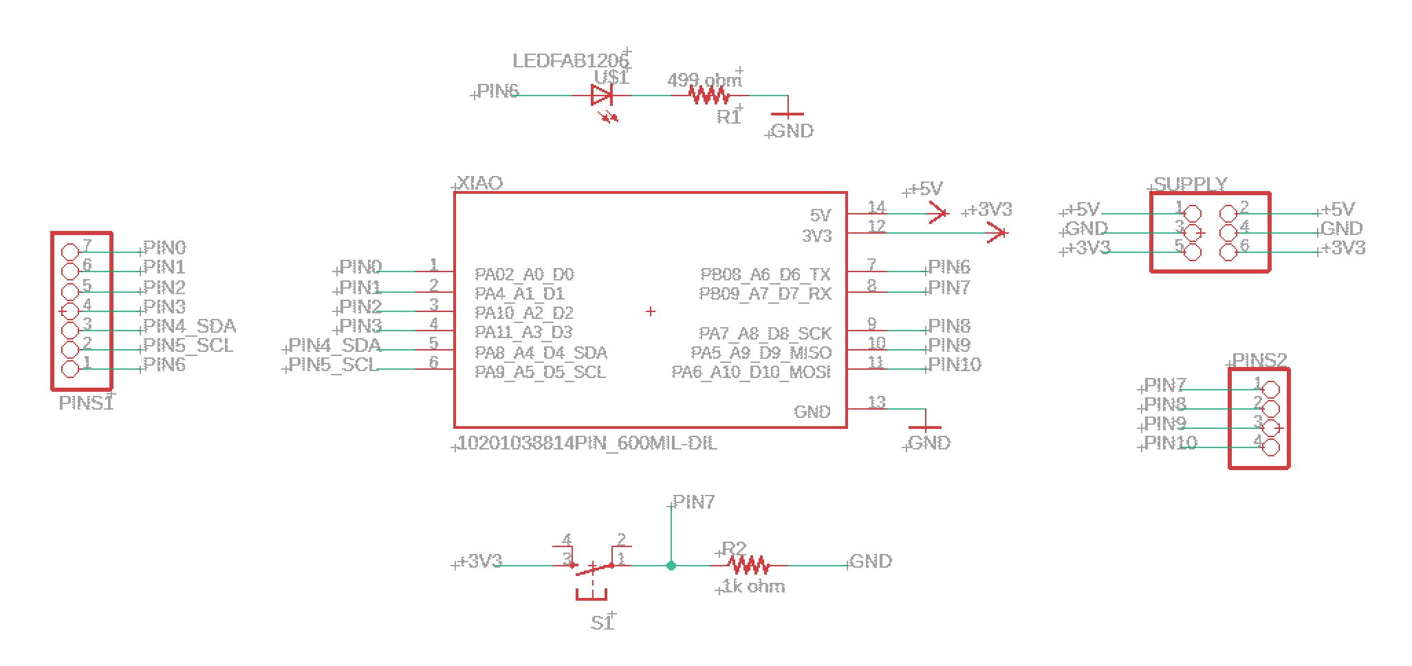
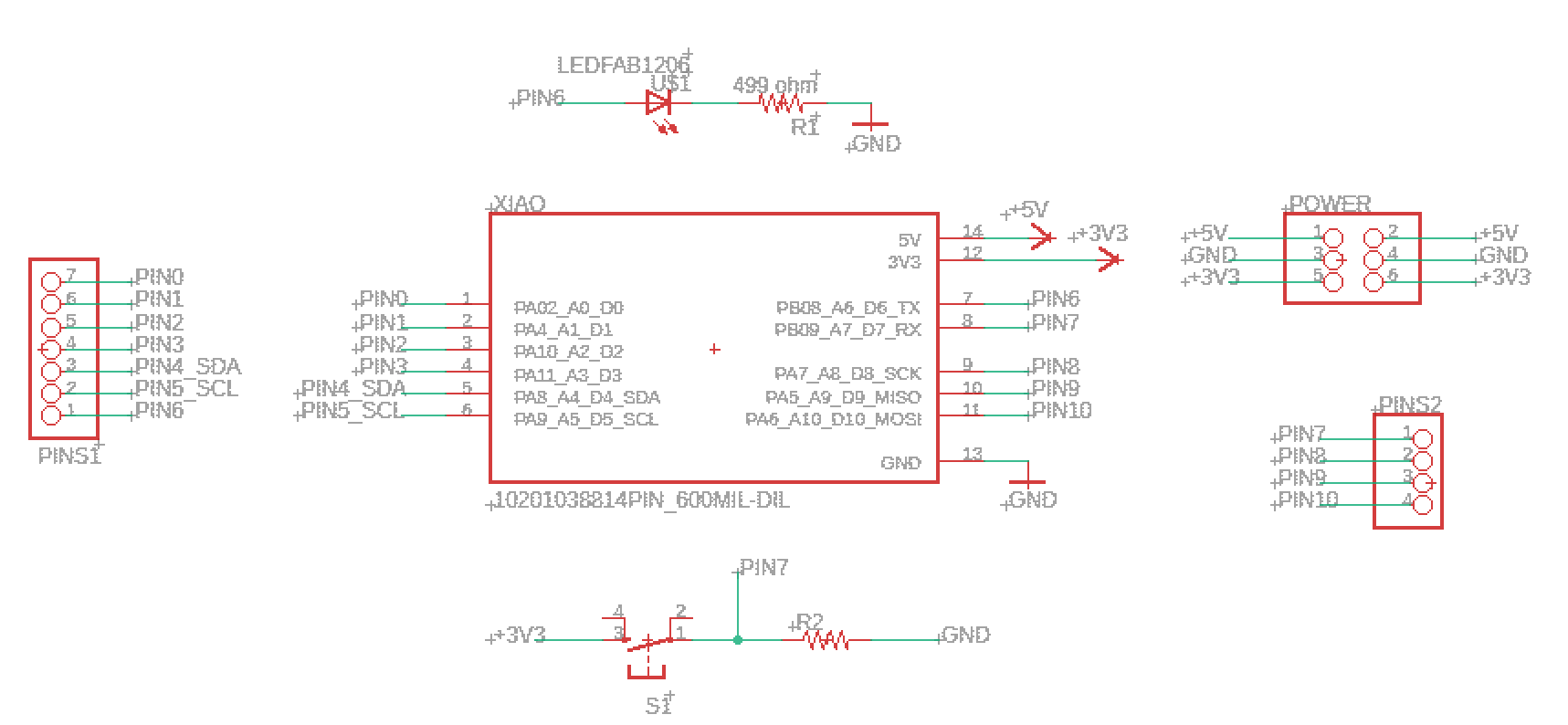
3) Schematic and Board Layout
- Schematic
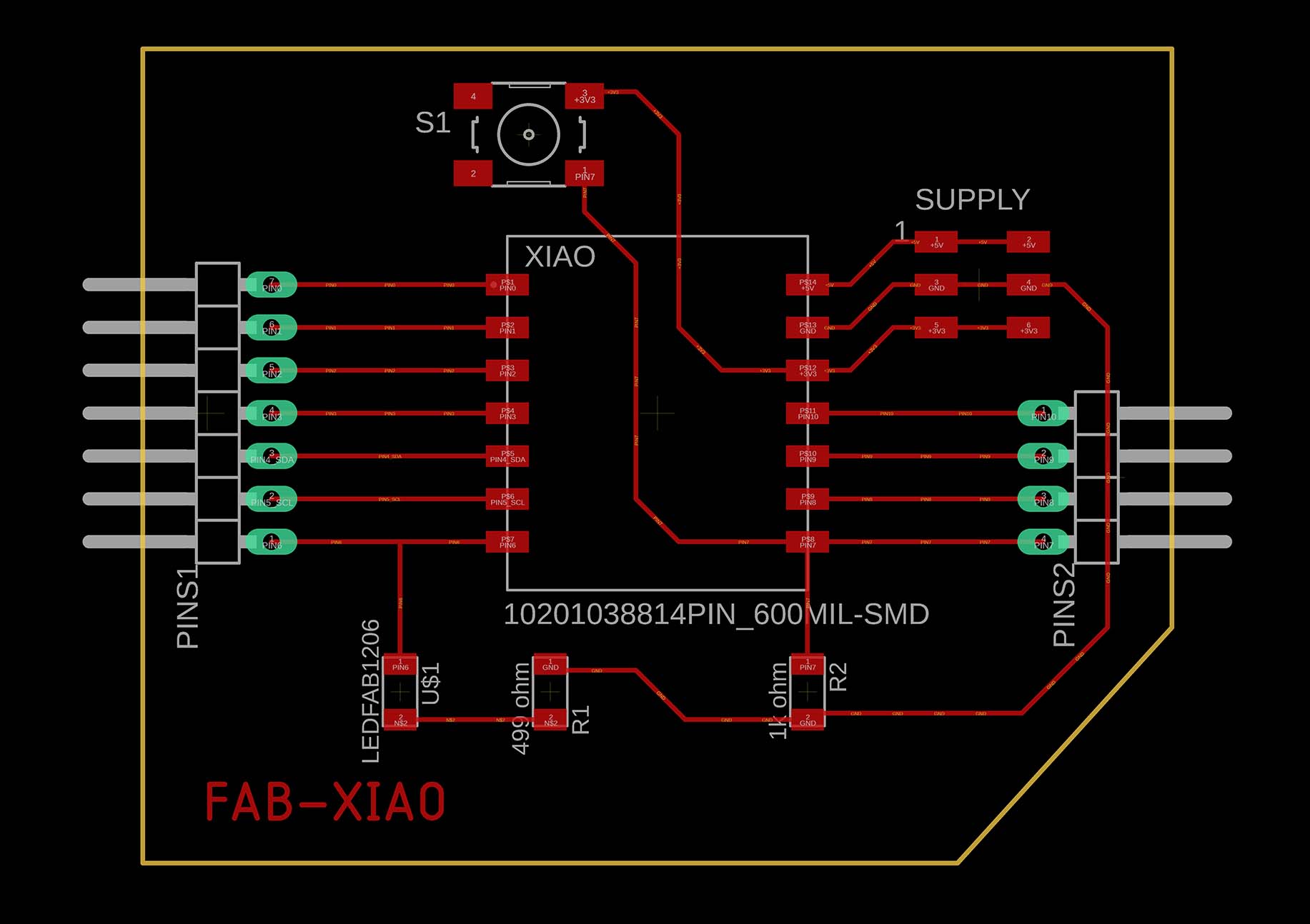
- Board Layout
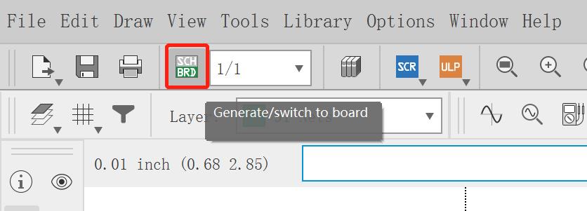
- Switch Views in EAGLE Click this button below to switch between schematic and board layout views.
A schematic in electronics is a drawing representing a circuit. It uses symbols to represent real-world electronic components. The most basic symbol is a simple conductor (traces), shown simply as a line. If wires connect in a diagram, they are shown with a dot at the intersection. (reference)
The board layout shows how the electrical components and traces will be laid out on the board.(reference)
4) Design Steps
- Add Library
- Add Dev-Board and Rename the Components
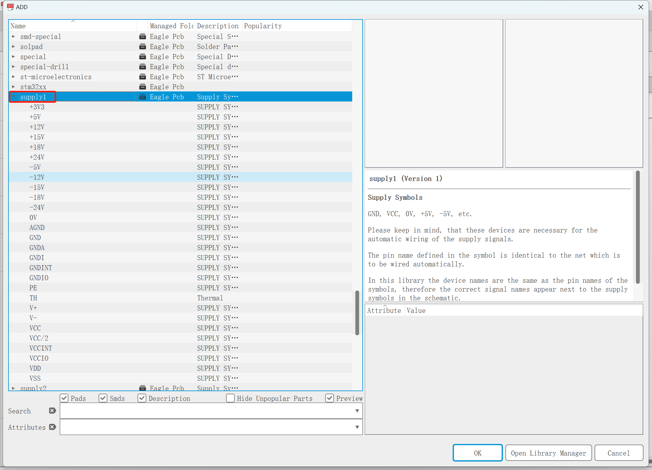
- Add Supply
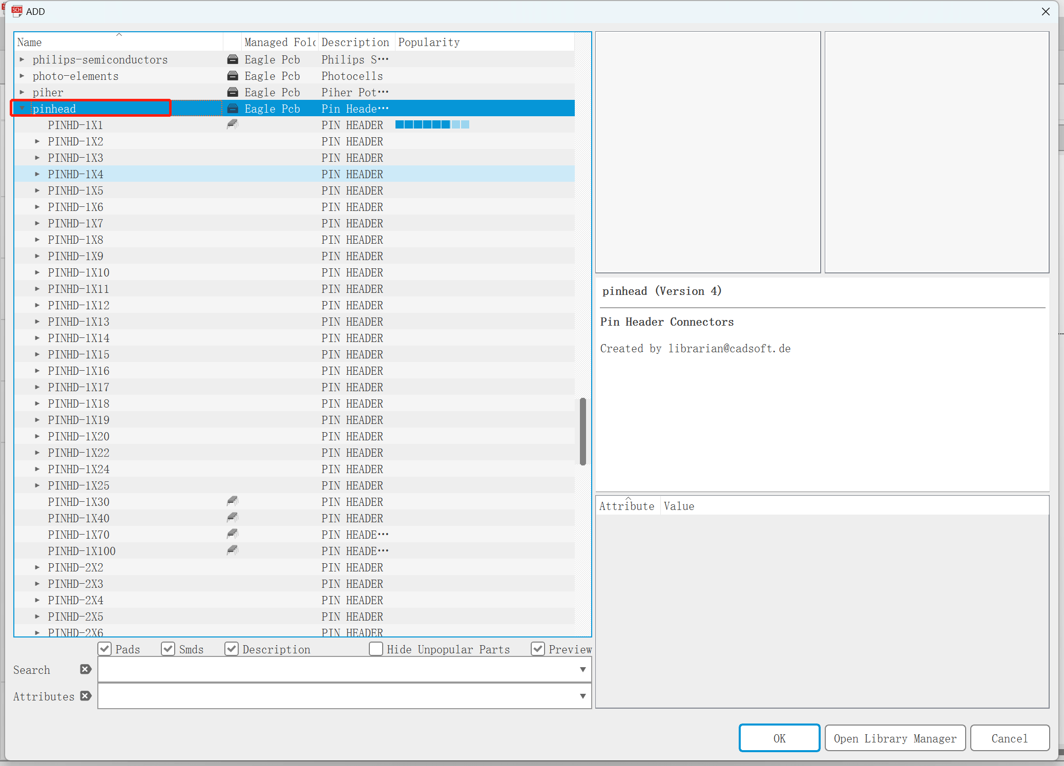
- Add Pinheads
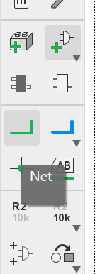
- Net
- Add Led and Button
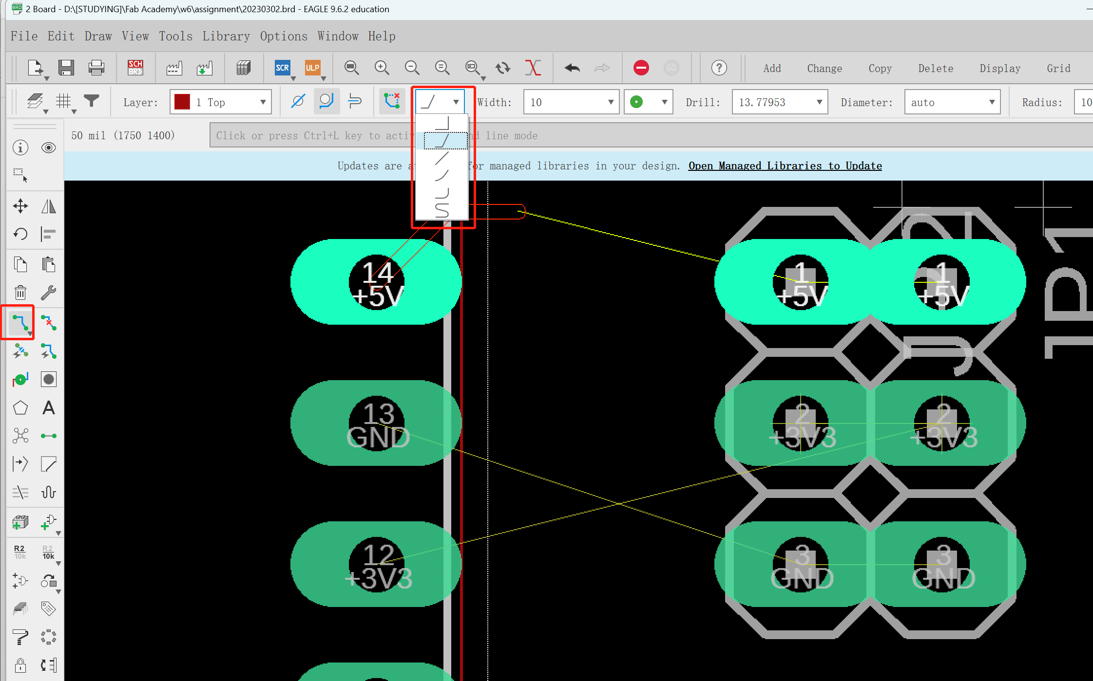
- Route in the Board View
- DRC
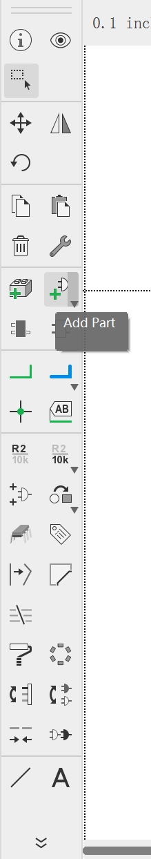
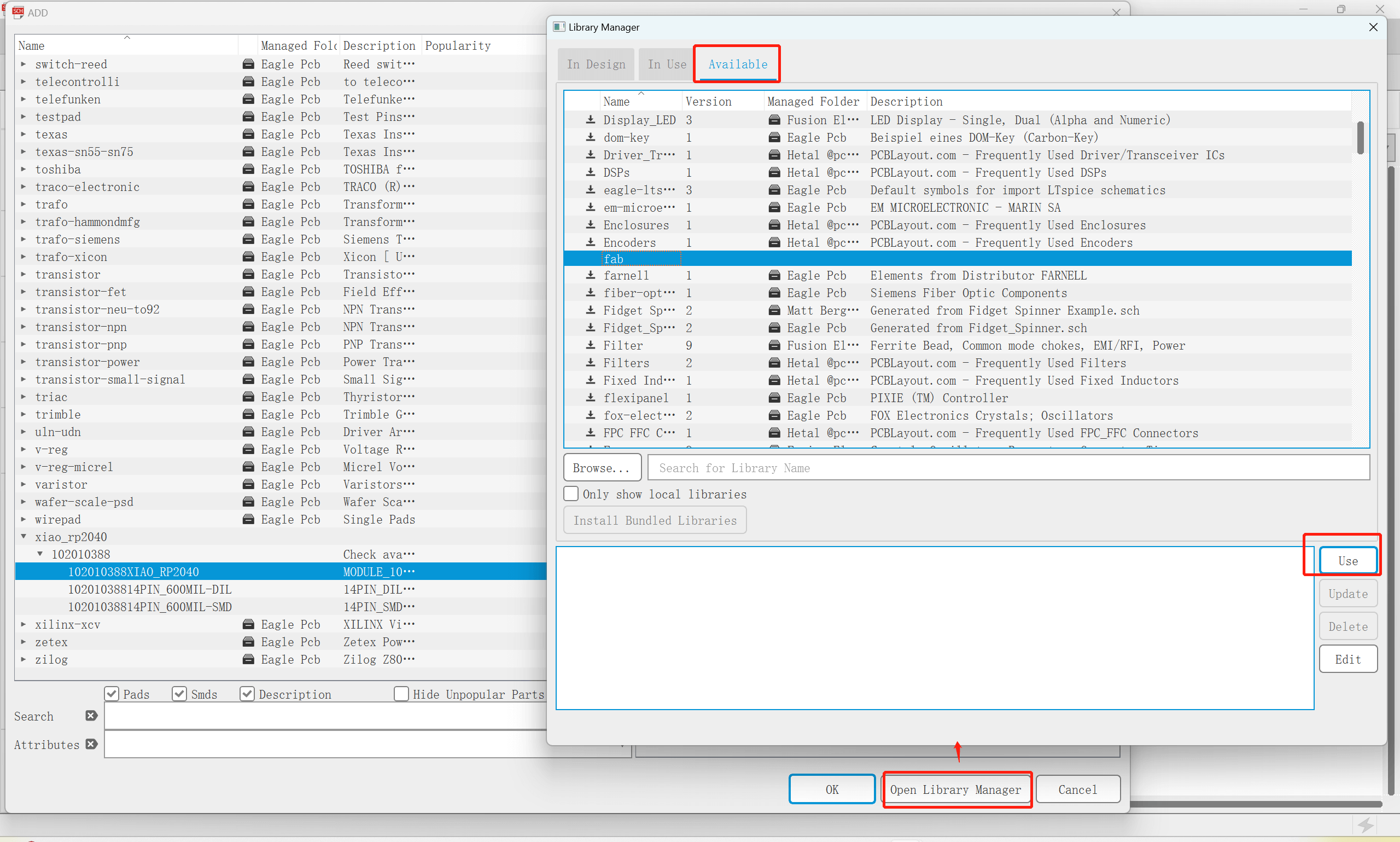
Download, Copy and Paste the Fab library to the "Users\Documents\EAGLE\libraries". Click "Add Part", there are already some default libraries. To add more, click "Open Library Manager" to load other available libraries. I added the "Fab" and "Xiao" libraries.
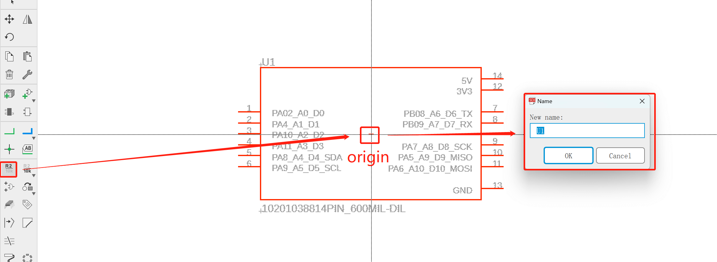
I added Seeed Xiao first. The default name is "U1". Click "Name" and then click the origin of the component to rename it to "Xiao". The same way to rename other components.
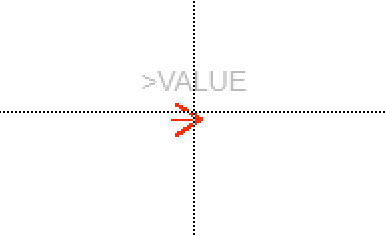
Right click to change direction of the arrow. The same way to change directions of other components.
For beginners, better to use SMD header. The default "pinhead" library are pad header.
Click "Net" to connect the components. Rename the net to connect with where has the same name.
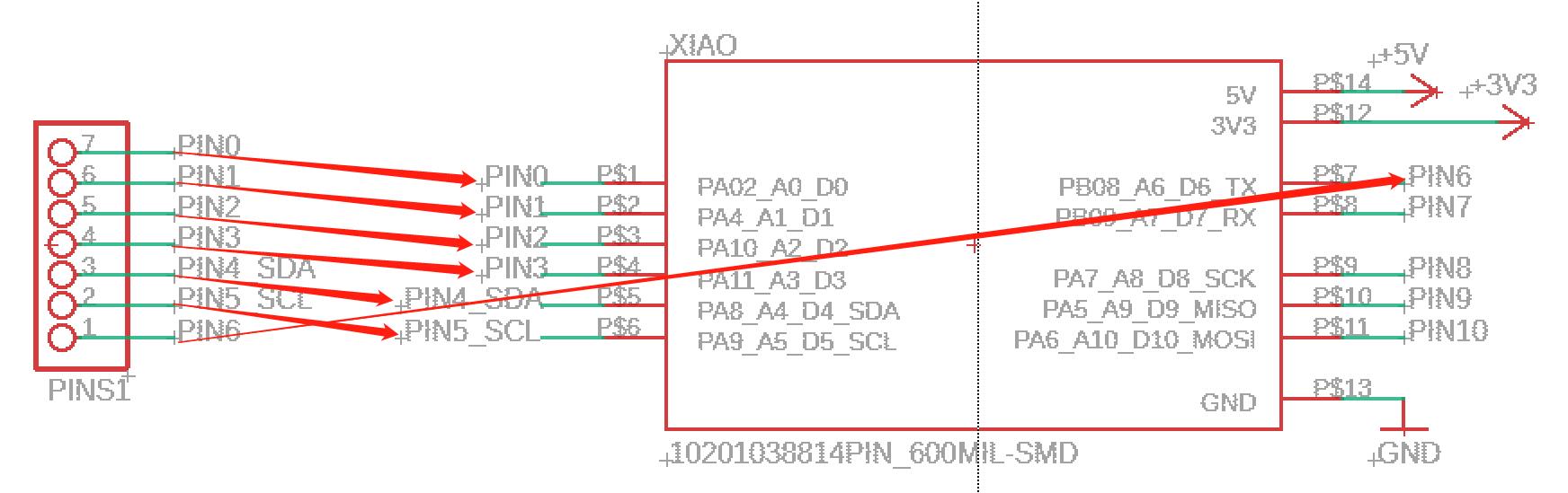
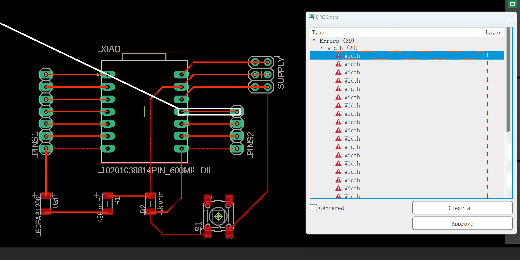
You can select wire bend and set the wire width on the top bar. I forgot to set the wire width at first so I got lots of warnings when doing design rule check.
There are some design rules for PCB design. Click "Tool→DRC“ to set the clearance and sizes.
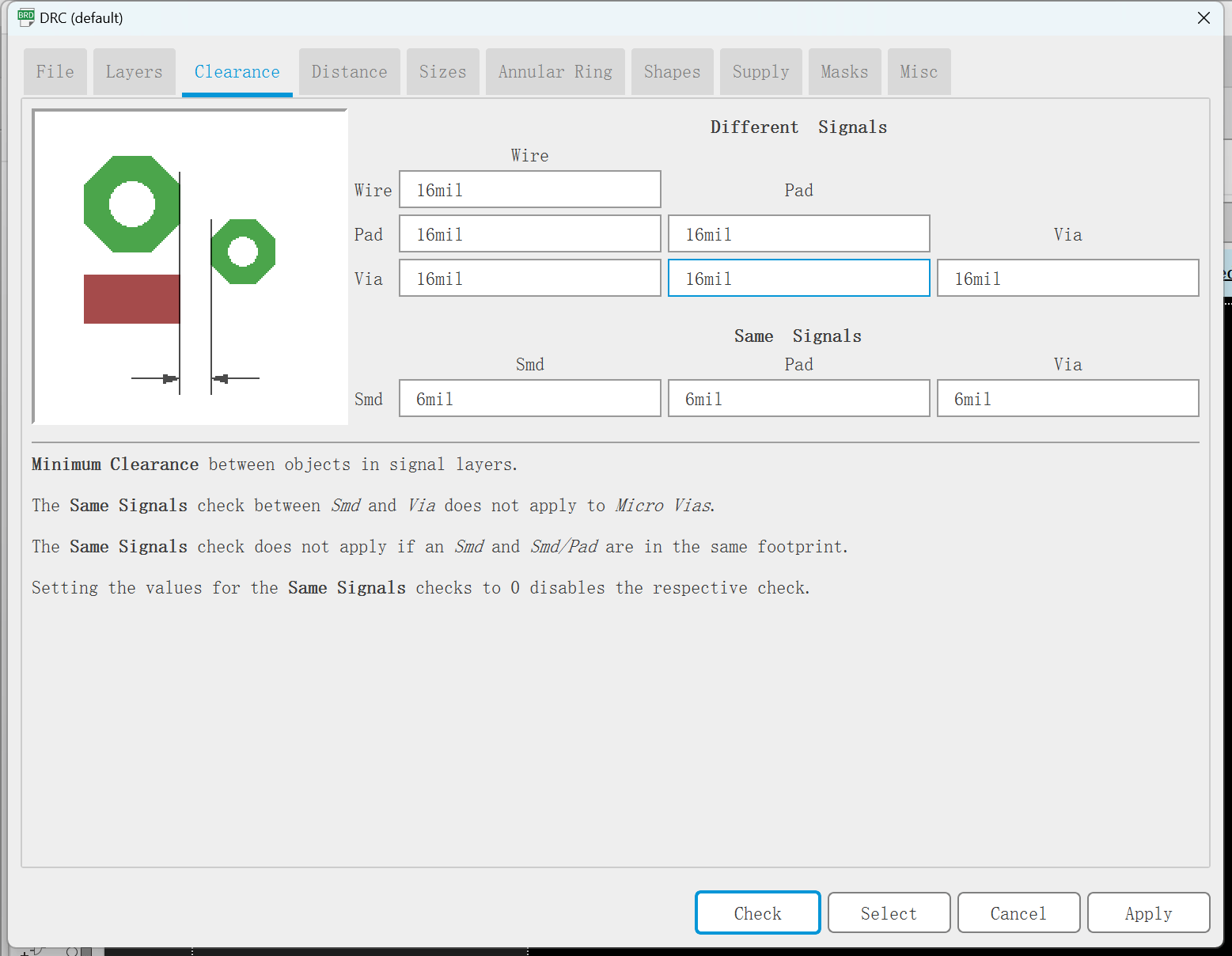
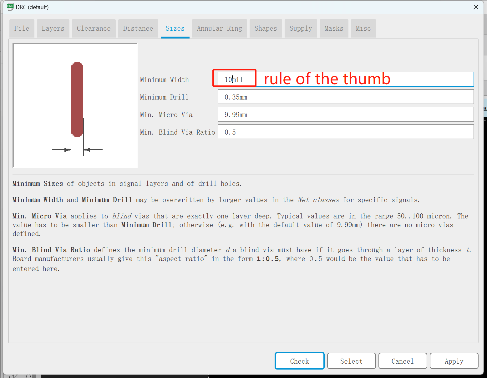
mil: thounsandth of an inch
DRC means "Design Rule Check", to make sure the circuit design can be manufactured by CNC. Traces and pads are not getting too closer and the traces width is wide enough to be cut out.
I forgot to set the wire width in the beginning, so I got all these width error. I had to "Ripup" all the wires and re-route them.
5) Pads and SMD
- Version 1 Pads
- Version 2 SMD
In the 1st verison, I didn't figure out the meaning of pads and SMD. I randomly chose all pads. This is more difficult for soldering.
So I drew version 2. I changed Xiao and supply pinhead to SMD, but still couldn't find the 1*7 and 1*4 SMD pinhead.
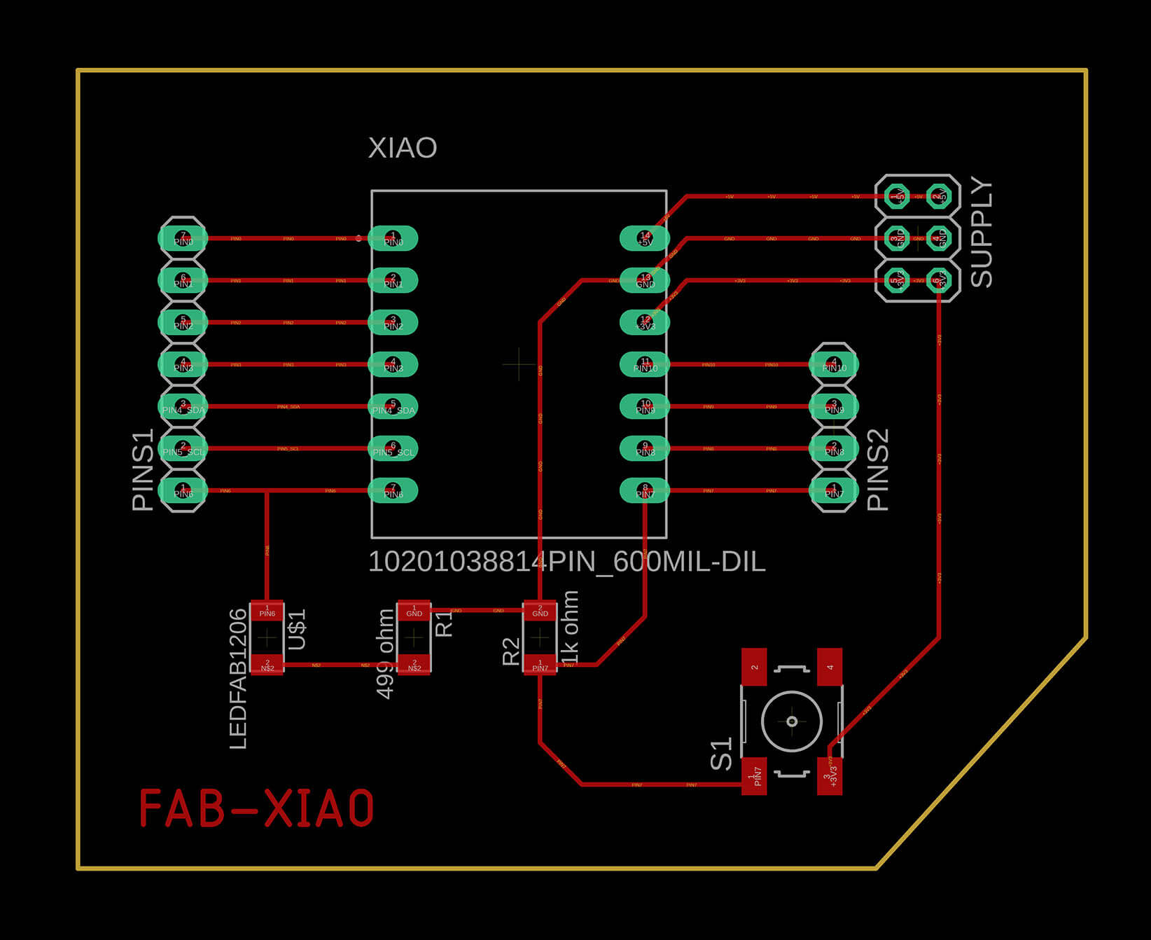
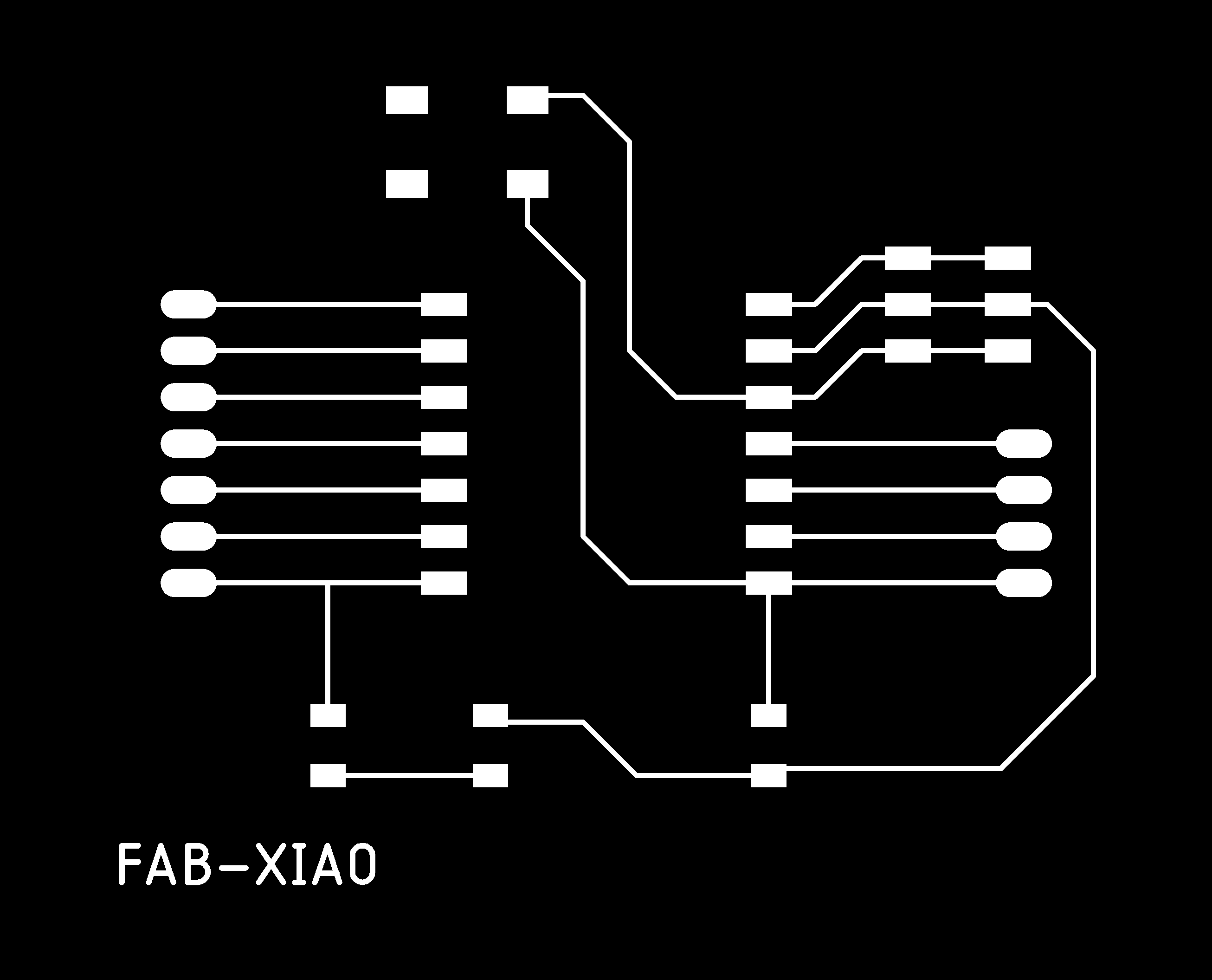
6) Final Work

| Part | Value | Device | Package | Description | |
| PINS1 | PINHD-1X7/90 | 1X07/90 | PIN HEADER | ||
| PINS2 | PINHD-1X4/90 | 1X04/90 | PIN HEADER | ||
| R1 | 499 ohm | RES-US1206FAB | R1206FAB | Resistor (US Symbol) | |
| R2 | 1k ohm | RES-US1206FAB | R1206FAB | Resistor (US Symbol) | |
| S1 | 6MM_SWITCH6MM_SWITCH | 6MM_SWITCH | OMRON SWITCH | ||
| SUPPLY | PINHD-2X3-SMD | 2X03SMD | PIN HEADER | ||
| U$1 | LEDFAB1206 | LEDFAB1206 | LED1206FAB | LED | |
| XIAO | 10201038814PIN_600MIL-SMD | 10201038814PIN_600MIL-SMD | 14PIN_SMD-600MIL | Check availability |