8. Electronics production
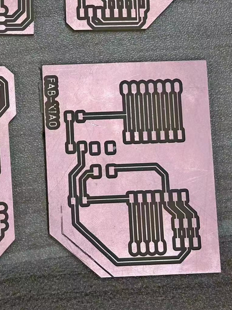
My first PCB:
1.1 Assignments of the Week
- Group assignment:
- Characterize the design rules for your in-house PCB production process: document feeds, speeds, plunge rate, depth of cut (traces and outline) and tooling.
- Document your work to the group work page and reflect on your individual page what you learned
-
Individual assignment:
- Make and test the development board that you designed to interact and communicate with an embedded microcontroller.
1.2 Group Assignment
Here is our grorup assignment of this week.
1.3 Individual assignment
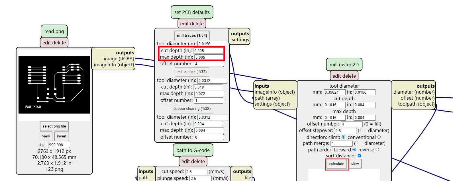
Genarate G-code with Mods
We use Mods to genarate tool path. It's easy to use. Open Mods in the browser and make 1/64 traces file and 1/32 outcut file seperately. Steps are detailed documented in our group assignment.
Due to a slight issue with the leveling of our CNC base, there were areas slightly lower on one side that weren't being milled. As a solution, we have adjusted the cut depth and max depth (in) 0.004 to 0.005 for the trace and changed 0.010 to 0.011 for the outline. This change ensures that even if there are slightly uneven surfaces, the milling process will still be thorough.
Export the NC files from the Mods, import them into Mach3, zero x, y and z axis, and we were be ready for milling.
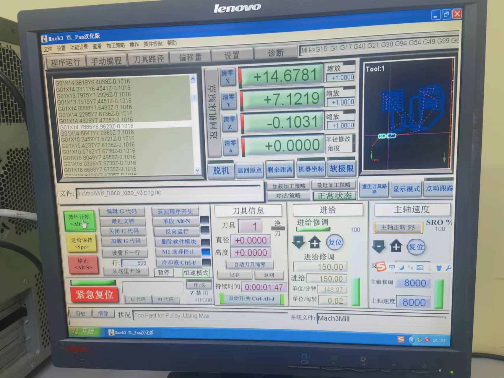
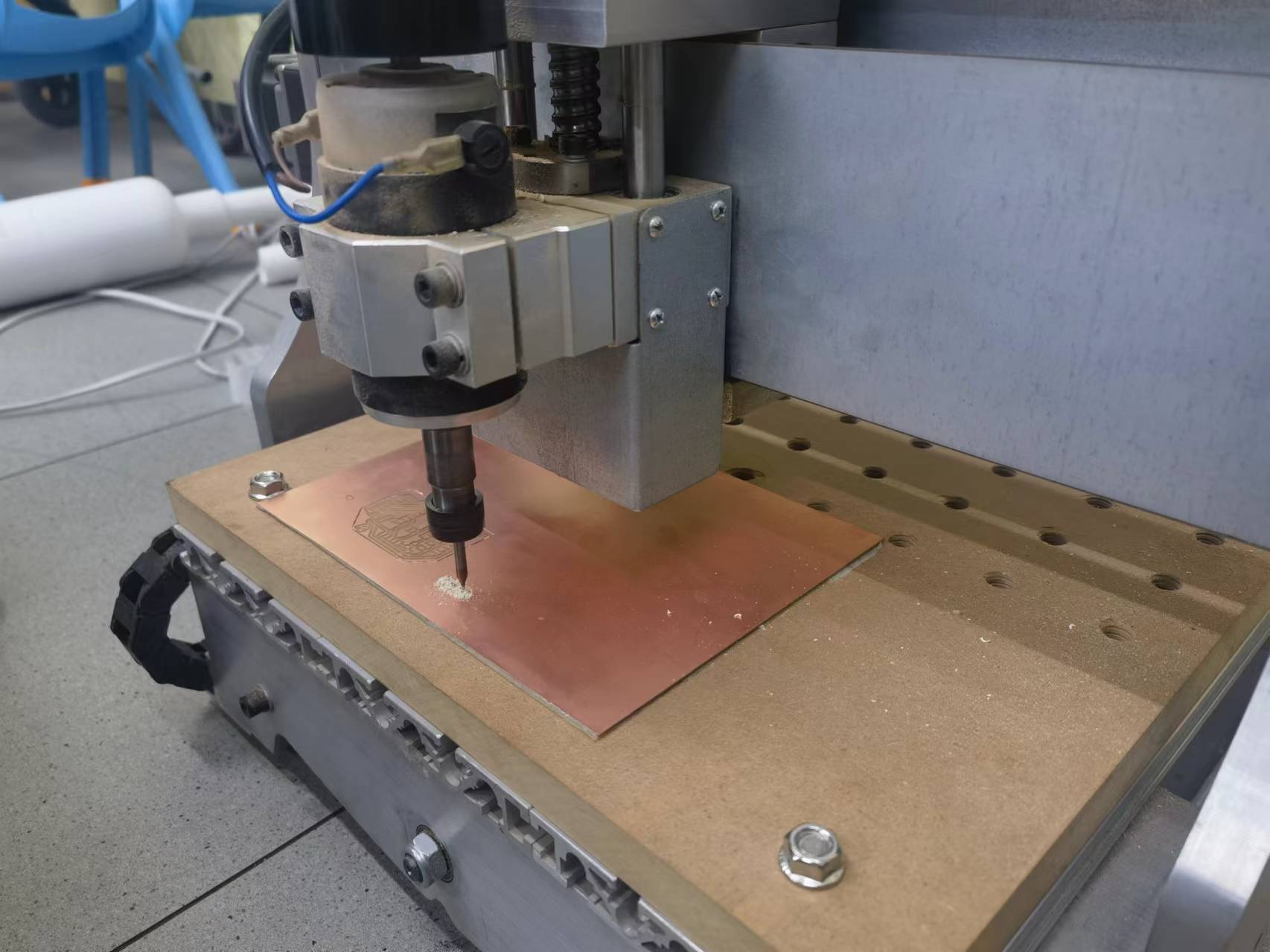
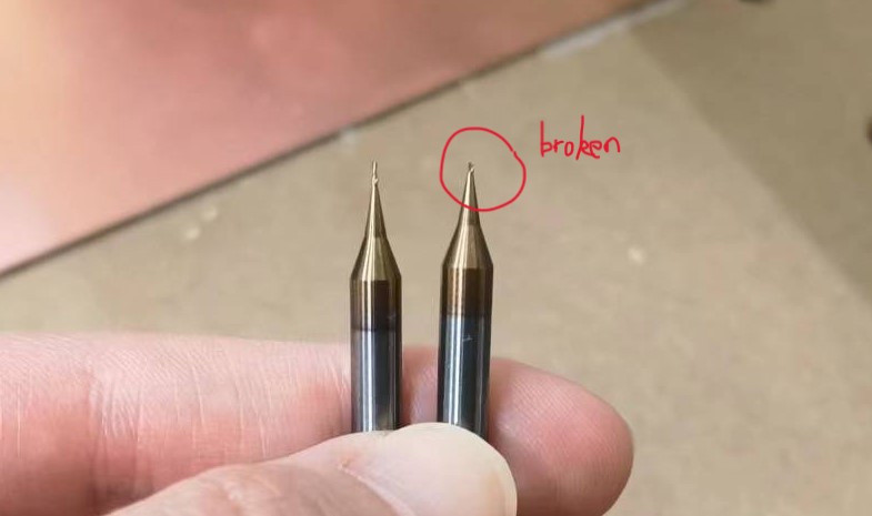
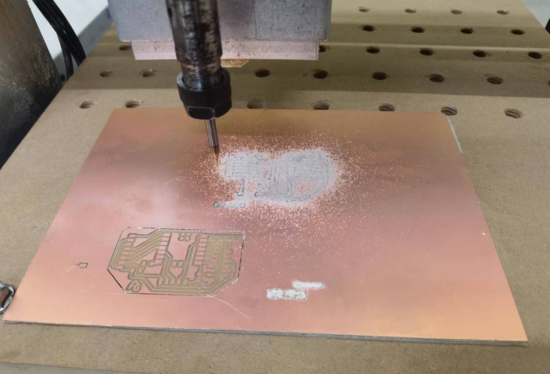
The First Attempt of the Trace
Due to the manual zeroing of the Z-axis on this machine, a slight error occurred when tightening the end mill. The milling depth was too deep, leading to the breakage of the end mill during the milling process.
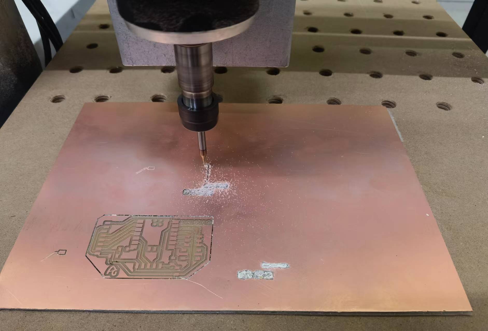
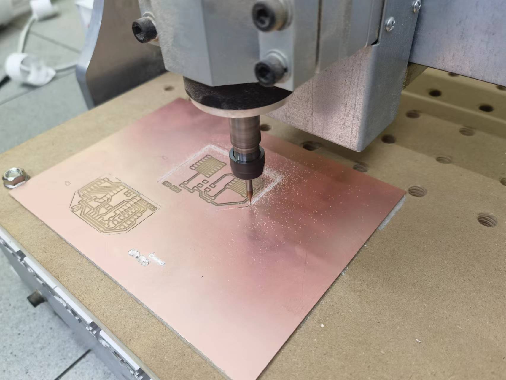
The Second Attempt of the Trace
After re-zeroing the Z-axis, the milling process of the trace file was completed successfully.
Milling the Outline
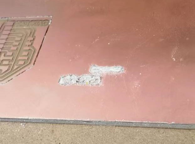
While milling the outline, I made another mistake. After switching from a 0.4 end mill to a 0.8 end mill, I accidentally clicked on the Y-axis movement button. I thought it would be fine as long as I didn't click to re-zero the Y-axis, but the outline still shifted in the Y-axis direction. Upon realizing this, I promptly halted the process, re-zeroed, and finally successfully completed the milling of the outline.
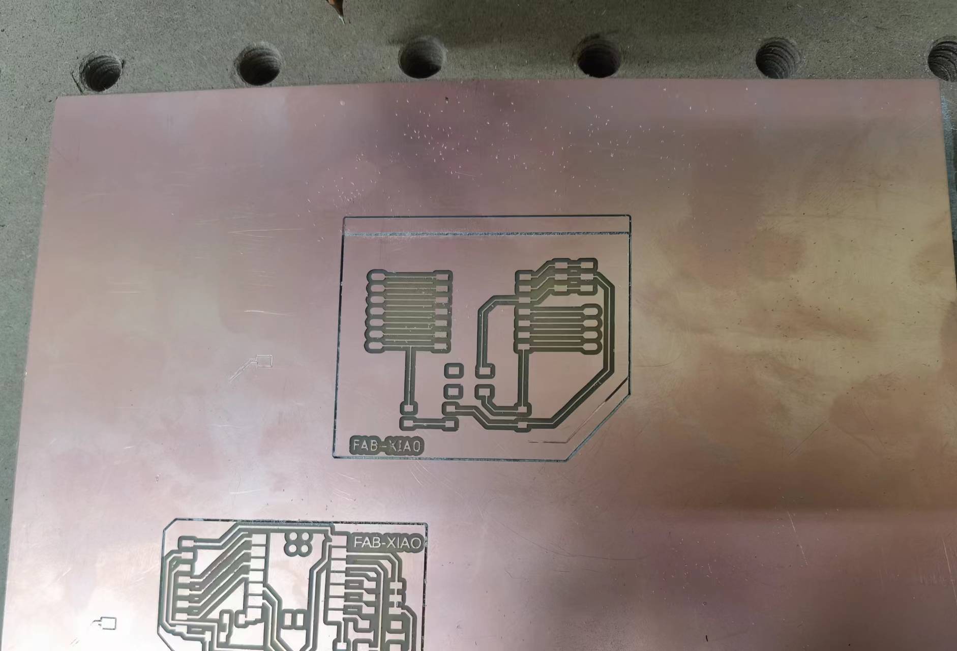 (My PCB bears the traces of my mistake.)
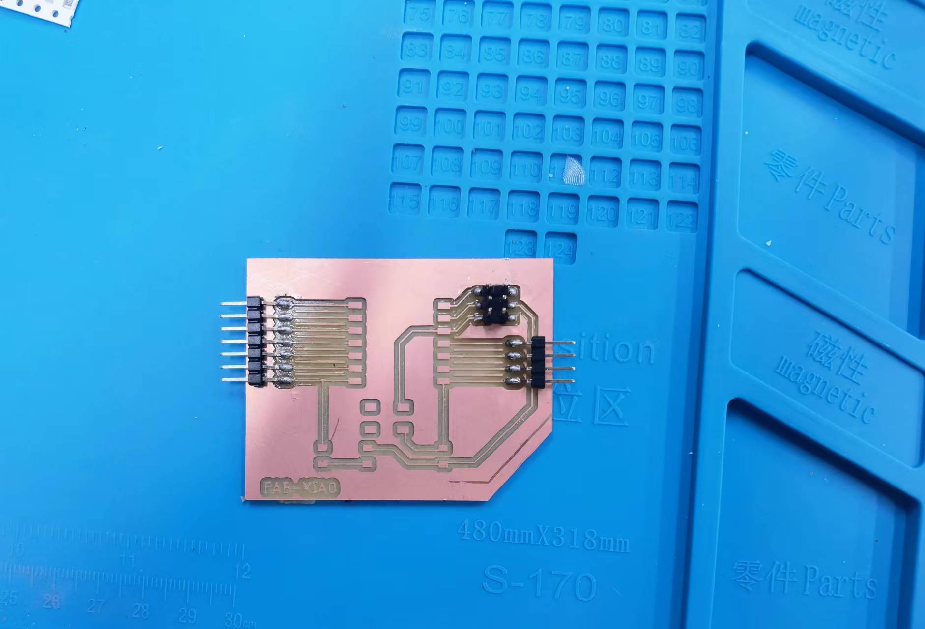
Milling is Done!
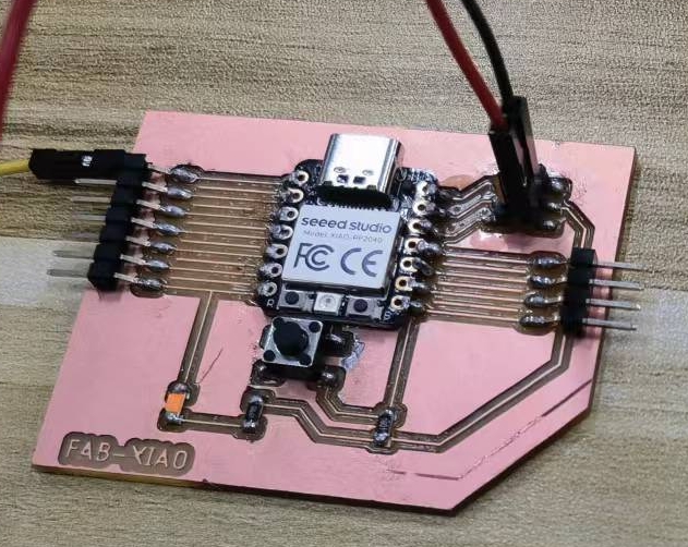
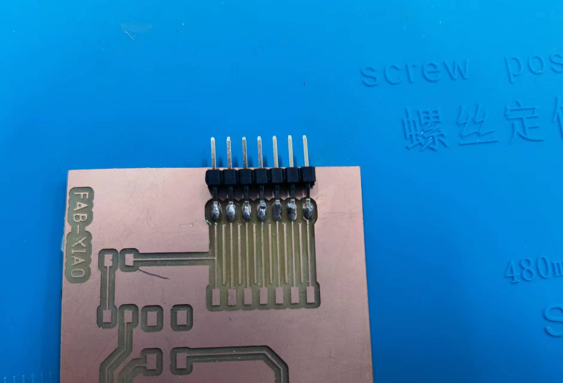
Soldering
Soldering is challenging, despite numerous practice sessions. When soldering the first row of pinheads, a few solder joints didn't turn out well. Fortunately, after testing, the functionality is still intact.
I summarized a few soldering tips for myself:
- Make sure the soldering iron tip is clean. If it oxidizes and turns black, clean it promptly with a steel wire ball.
- Use flux, but avoid using too much.
- Don't leave the soldering iron tip on the component for too long. Prolonged high temperatures can lead to soldering failures.
Soldering Process:
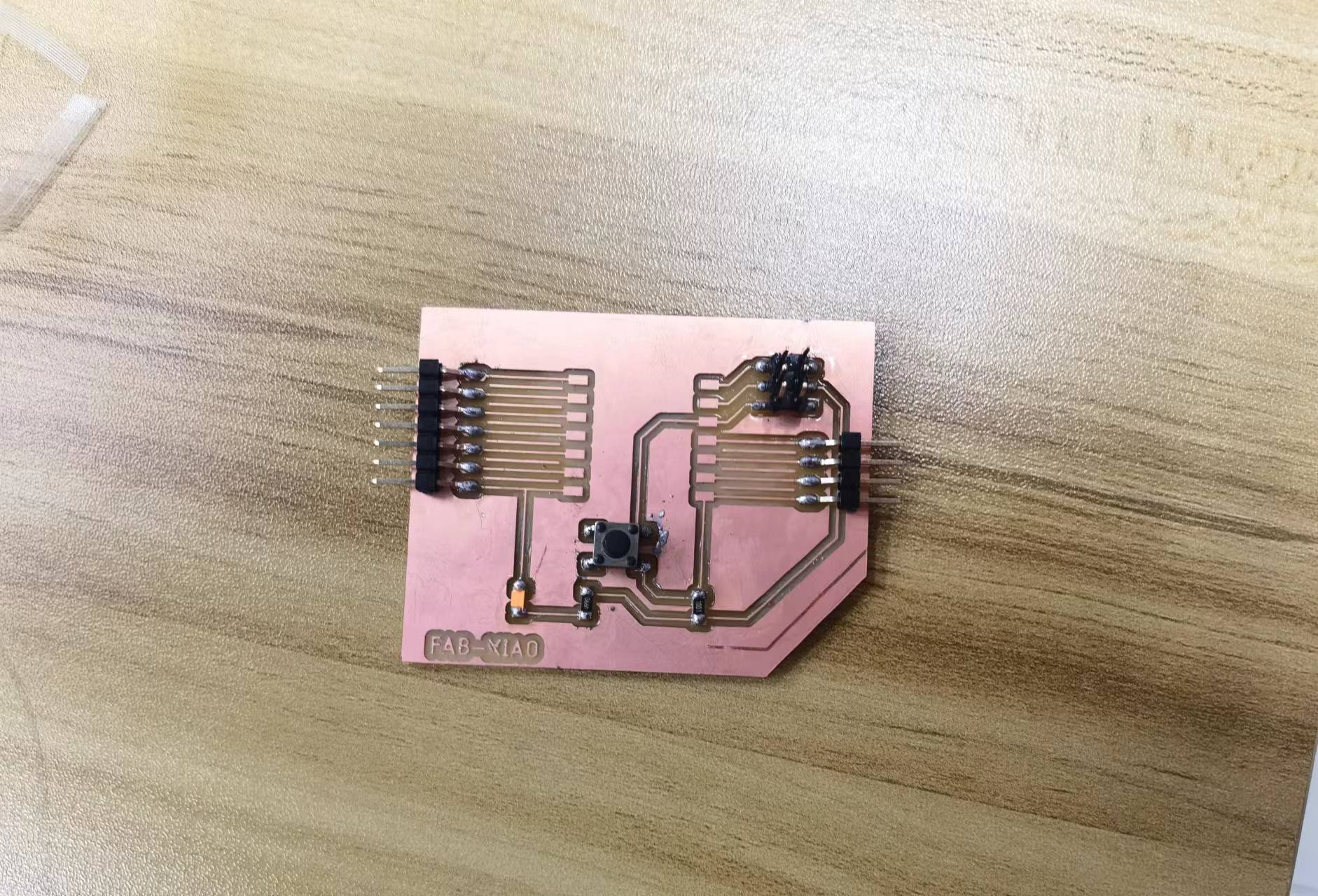
Heroshot:
Test and Demonstrate
I made a modification on the basis of the sample code on the official website. When the sensor detects a magnetic materials, it will display: "Magenetic Sensor is Attracted." in the serial monitor, and light up the LED on the Fab-Xiao development board. Otherwise, the LED is off, and the serial port The monitor display nothing.
int inputPin = D2;               // choose the input pin
int val = 0;                    // variable for reading the pin status
void setup() {
  pinMode(inputPin, INPUT);
  pinMode(D6,OUTPUT);
  Serial.begin(9600);
}
void loop(){
  val = digitalRead(inputPin);  // read input value
  if (val == HIGH) {            // check if the input is HIGH
    Serial.println("Magenetic Sensor is Attracted."); // print message in the serial monitor
    digitalWrite(D6,HIGH);  // turn LED ON
  } else {
    Serial.println();  // print nothing in the serial monitor
    digitalWrite(D6,LOW);  // turn LED off
  }
  delay(200);
}
Video: