4. Embedded programming
It's been a crazy week for me. In addition to programming, it also takes time to understand the important features of development boards and micro controllers. Although brwosing through datasheets gives me a headache, it's still a lot of fun when the program works.
1.1 Assignments of the Week
- Group assignment:
- Compare the performance and development workflows for other architectures.
- Document your work to the group work page and reflect on your individual page what you learned
-
Individual assignments:
- Browse through the datasheet for your microcontroller.
- Program a microcontroller development board to interact and communicate.
1.2 Group Assignment
We tried to use Arduino Uno, Mirco-Bit and Seeed Xiao. Here is the documentation.
1.3 Datasheets Reading
According to the definition of wikipedia, A datasheet is a document that summarizes the performance and other characteristics of a product, machine, component (e.g., an electronic component), material, subsystem (e.g., a power supply), or software in sufficient detail that allows a buyer to understand what the product is and a design engineer to understand the role of the component in the overall system.
1) Arduino Uno
The Arduino UNO R3 is the perfect board to get familiar with electronics and coding.
📃Datasheet of Arduino Uno R3
- Board Topology
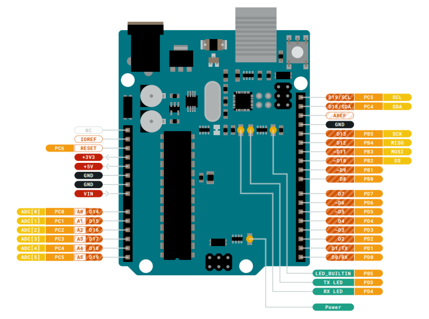
- Connector Pinouts
- A0~A5: Analog Inputs
- D0~D13: Digital Inputs and Outputs. Among them, D3, D5, D6, D9, D10, and D11 can output analog signals.
- GND: Ground
- VIN: Voltage Input
- MOSI: SPI Main Out Secondary In
- MISO: SPI Main In Secondary Out
- SCK: SPI serial clock output
- SDA: I2C Data Line
- SCL: I2C Clock Line
- +3.3V: 3.3V power rail
- +5V: 5V power rail
- IDE
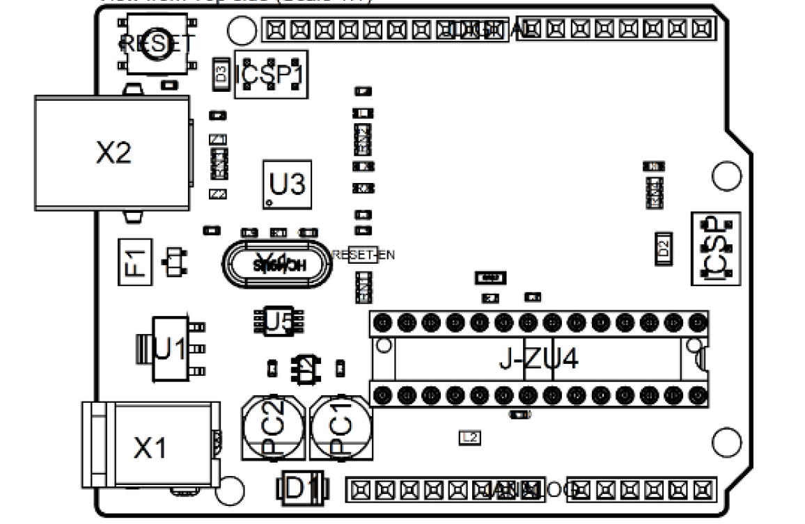 |
 |
The Main Processor is a ATmega328P running at up tp 20 MHz. Most of its pins are connected to the external headers, however some are reserved for internal communication with the USB Bridge coprocessor.
I2C and SPI are serial communications that are widely used for peripherals and microcontrollers for information in and out.
There is a metaphor by Rico that helps to understand what serial communication protocol is. I2C and SPI are like Type-C, HTML and USB connector on our laptop, they can only connect the specific devices that use the same connector. Some electronics use the specific serial communication protocols, and they can be only connected on the corresponding pinouts that use the same protocols. Otherwise it won't work. So it is important to read the datasheet of the electronic when using it, to clearfy which serial communication it uses.
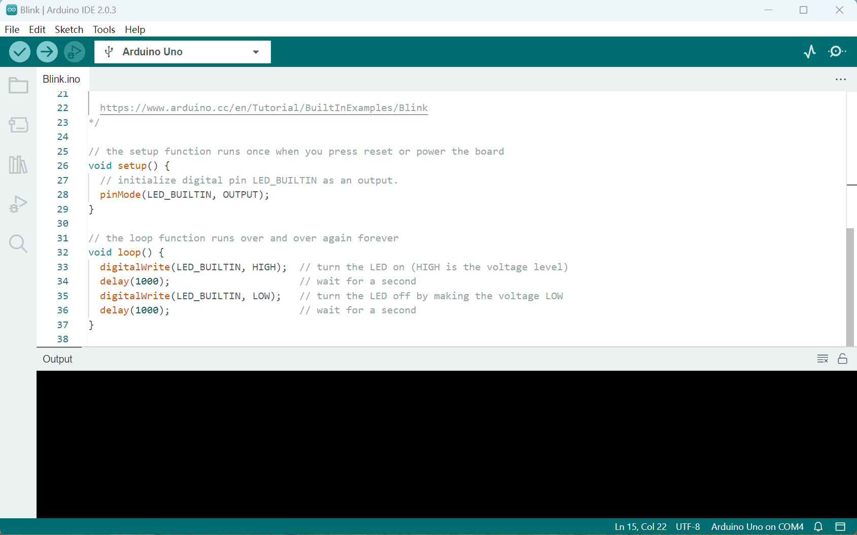
Arduino Desktop IDE is used to connect the Arduino UNO to the computer. A Micro-B USB cable is needed. This also provides power to the board, as indicated by the LED.
2) ATmega328P
ATmega328P is the main processor of Arduino Uno. It is a high performance, low power AVR 8-bit microcontroller, with advanced RISC architecture.
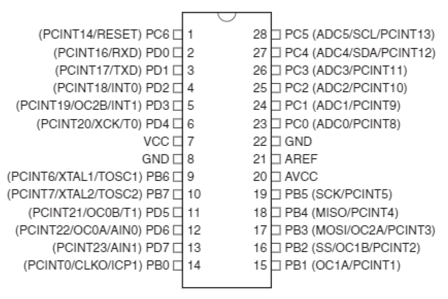
- VCC: Digital Supply Voltage
- GND: Ground
- Port B: Port B is an 8-bit bi-directiona I/O port with internal pull-up resistors.
- Port C: Port C is a 7-bit bi-directional I/O port with internal pull-up resistors.
- Port D: Port D is an 8-bit bi-directiona I/O port with internal pull-up resistors.
I was confused about these ports. Sevario gave me an simple explanation to help understand: ATmega328P is a processor developed by engineers. They don't care about whether it's convinient for the users. When you use it, you must read the complicated datasheet to clearfy each port on the chip. But Arduino was created by designers. Designers want it to be user friendly. That's why we have pinouts like D0~D13 and A0~A5. It becomes more convenient to use.
3) RP2040
RP2040 is a low cost microcontroller device with the quality, cost and simplicity of the Raspberry Pi. It has two symmetric processor cores and high internal bandwidth, making it useful for signal processing and video. The chip has a large amount of internal RAM but uses external flash, allowing you to choose how much memory you need.
📃Datasheet of RP2040
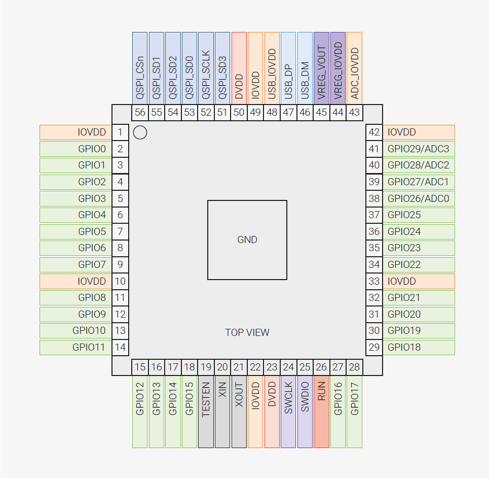
- GPIOx: General-purpose digital input and output. RP2040 can connect one of a number of internal peripherals to each GPIO, or control GPIOs directly from software.
- GPIOx/ADCy: General-purpose digital input and output, with analogue-to-digital converter function. The RP2040 ADC has an analogue multiplexer which can select any one of these pins, and sample the voltage.
- QSPIx: Interface to a SPI, Dual-SPI or Quad-SPI flash device, with execute-in-place support. These pins can also be used as software-controlled GPIOs, if they are not required for flash access.
- USB_DM and USB_DP: USB controller, supporting Full Speed device and Full/Low Speed host.
- IOVDD: Power supply for digital GPIOs, nominal voltage 1.8 V to 3.3 V.
- VREG_VOUT: Power output for the internal core voltage regulator, nominal voltage 1.1 V, 100 mA max current.
1.4 Programming a Development Board
As a beginner, I started with using Arduino Uno. There are detailed tutorials in Chinese on dfrobot's official website. Following the guide of tutorials, I tried several projects.
1) Fading Light
- PWM
- Duty Cycle
- Usage
- analogWrite(pin,value)
- Code
To create an LED that seems as if it's fading, I need to use pinouts that can output analog signals. This involves the PWM signal. PWM(Pulse Width Modulation) is a technology that obtains analog quantities through digital methods. Digital control to form a square wave, the square wave signal only has two states of switch (that is, the high and low of our digital pin). By controlling the ratio of on and off durations, a voltage varying between 0 and 5V can be simulated. The time taken to turn on (academically called high level) is called pulse width, so PWM is also called pulse width modulation.
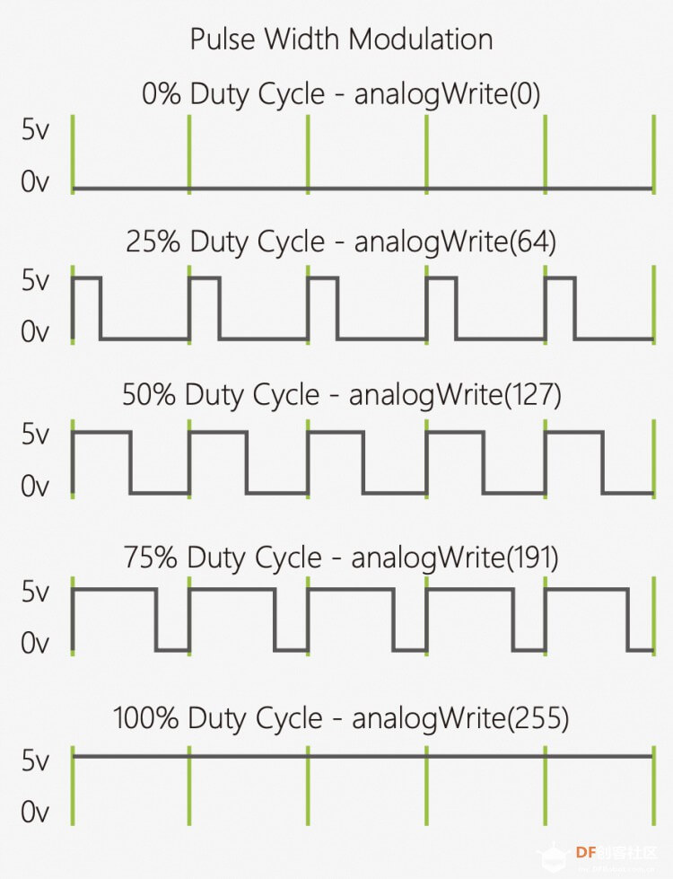
Refers to the percentage of the duration of the high level in a period to the duration of the low level
PWM is mostly used to adjust the brightness of LED lights. Or the rotation speed of the motor, the speed of the wheel driven by the motor can be easily controlled.
The analogWrite function can take integers between a value of 0 - 255, where the higher, the brighter the LED should become. When using this function, you can only D3, D5, D6, D9, D10, D11 pinouts.
Adjust the values of time and increment in the FadeOn and FadeOff Functions, you will see different fading time intervals.
⬇️ This is the sample code from dfrobot:
         int ledPin = 10;

          void setup() {
                pinMode(ledPin,OUTPUT);
          }

          void loop(){
                fadeOn(1000,5);
                fadeOff(1000,5);
          }

          void fadeOn(unsigned int time,int increment){
                  for (byte value = 0 ; value < 255; value+=increment){
                      analogWrite(ledPin, value);
                          delay(time/(255/increment));
                  }
          }

          void fadeOff(unsigned int time,int decrement){
                  for (byte value = 255; value >0; value-=decrement){
                      analogWrite(ledPin, value);
                          delay(time/(255/decrement));
                  }
          }
2) Temperature Alarm
- LM35 Temperature Sensor
- +Vs: connected to power supply
- Vout: connected to voltage output
- GND: connected to ground
- Serial.begin(9600)
- Serial.print(val) & Serial.println(val)
- analogRead(pin)
- Code
This is a sensor that is accurate to +1/4°C without additional calibration processing.
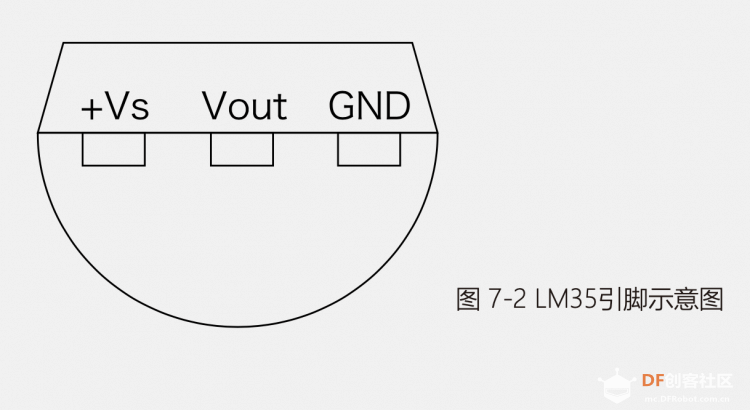
Pins:
In the setup function, you need to initialize the serial port baud rate, that is, the data transmission rate. If some specific wireless modules have special requirements for the baud rate, the baud rate setting only needs to be consistent with the serial monitor.
These functions print data in serial monitor. "Println" prints data followed by a carriage return character and a newline character.
What this function reads is the voltage value of the temperature, which is output in the form of 0~1023. The LM35 temperature sensor corresponds to 1 degree Celsius for every 10mV. The voltage value read from the sensor ranges from 0 to 1023. Divide the value into 1024 parts, multiply the result by 5, and map it to 0~5V, because 10mV per degree needs to be multiplied by 100 to get a double type temperature value, and finally assigned to the data variable. The calculation can be found in the datasheet.
⬇️ This is the sample code from dfrobot:
            float sinVal;
            int toneVal;
            unsigned long tepTimer ;

            void setup(){
                pinMode(8, OUTPUT);
                Serial.begin(9600);
            }

            void loop(){
                int val;
                double data;
                val=analogRead(0);
                data = (double) val * (5/10.24);

                if(data>23){
                      for(int x=0; x<180; x++){
                        sinVal = (sin(x*(3.1412/180)));
                        toneVal = 2000+(int(sinVal*1000));
                        tone(8, toneVal);
                        delay(2);
                      }
                 } else {
                       noTone(8);
                 }

                if(millis() - tepTimer > 500){
                         tepTimer = millis();
                         Serial.print("temperature: ");
                         Serial.print(data);
                         Serial.println("C");
                   }
            }