
This week's assignment is about using one or several input devices in conjunction with a microcontroller evaluating analog and digital signals.
To perform this task we will create a printed circuit board where different parameters will be measured, including:
With this sensor, the appearance of an electric field is detected by charge separation inside a conductor, specifically we will use the A1325 code which has an analog output proportional to this electric field, you can see its datasheet here.
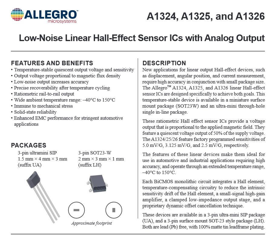
Figure N°1
To evaluate light we will use a phototransistor, it works at the 940nm wavelength, this sensor modulates the flow of current based on the incidence of light, so it is used in conjunction with a resistor as a voltage divider to have an analog output, you can see its datasheet here.
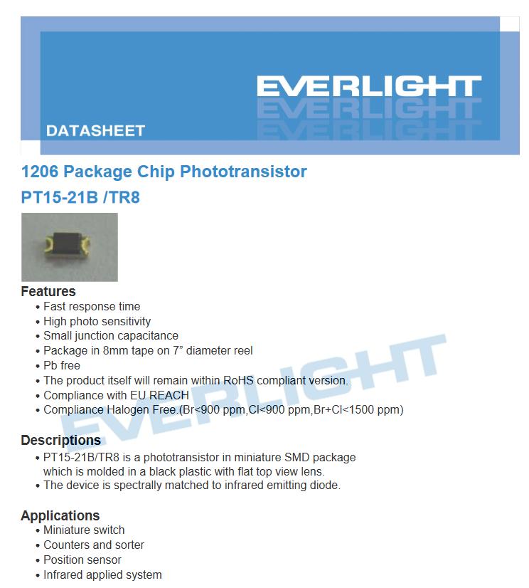
Figure N°2
To obtain a digital data output we will use a reed switch which is normally open and by having a magnet nearby make the terminals come into contact closing the circuit, you can see its datasheet here.
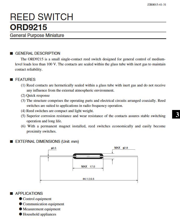
Figure N°3
The next input that we will use will be the Step Response, it is a sensor that makes use of two conductive copper tapes. This can be used to calculate the amount of material they have in the middle of both, in our case we will evaluate the amount of food that is inside a cat bowl.
This design is based on documented work by Adrian Torres. In this design, one of the copper tapes is used as a TX electrode, a series of pulses is sent that allows more or less that series of pulses to pass to the other RX tape depending on what is in between, this other electrode will be connected between two resistors, one pull-up and one pull-down of 1M and an analog input.
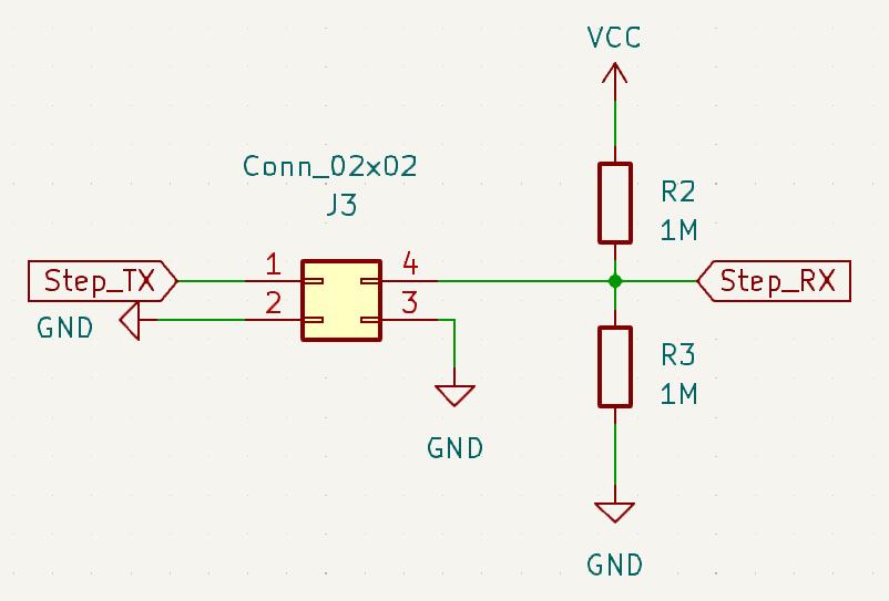
Figure N°4
In order to read the values of these input devices we will use an RP2040 microcontroller with a Seeed module since it can read both analog and digital values, we have already used this module in week 04 - Embedded Programming.
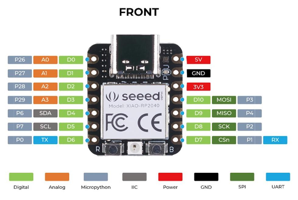
Figure N°5
For the schematic design we will use labels to identify the output of each of the sensors, additionally we will put pinheaders to externally connect other sensors with communication protocols such as UART or I2C.
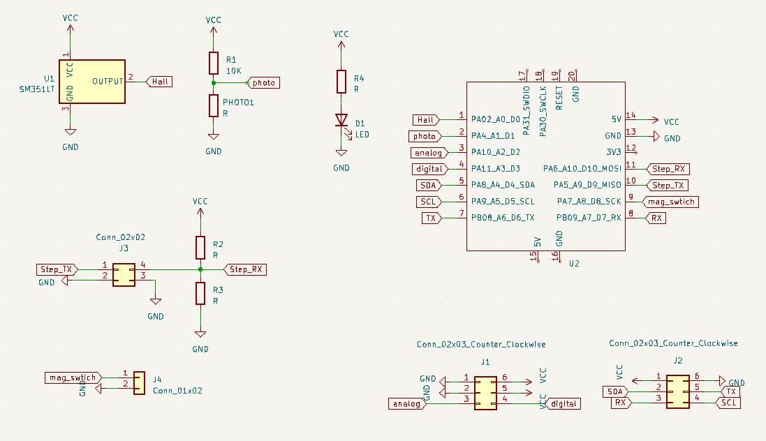
Figure N°6
And so would be the final design of the printed circuit board.

Figure N°7
In order to manufacture it, we repeat the process described in week 08 - Electronics Production, we will export the tracks in SVG format, we will increase the DPI and we will invert the image.
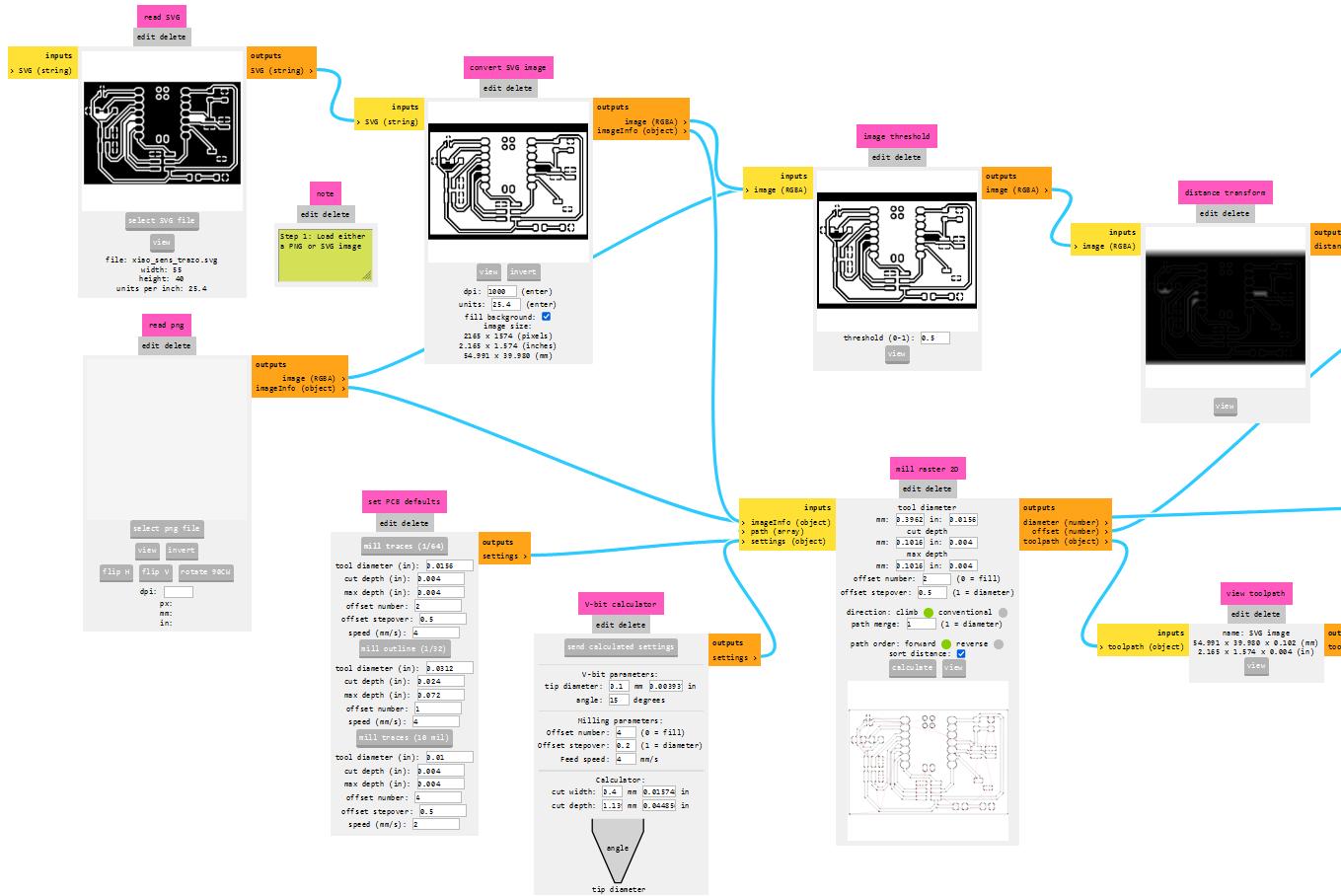
Figure N°8
This would be the path that the milling machine will make to manufacture the plate.

Figure N°9
Let's get this result where all the lines are correct.
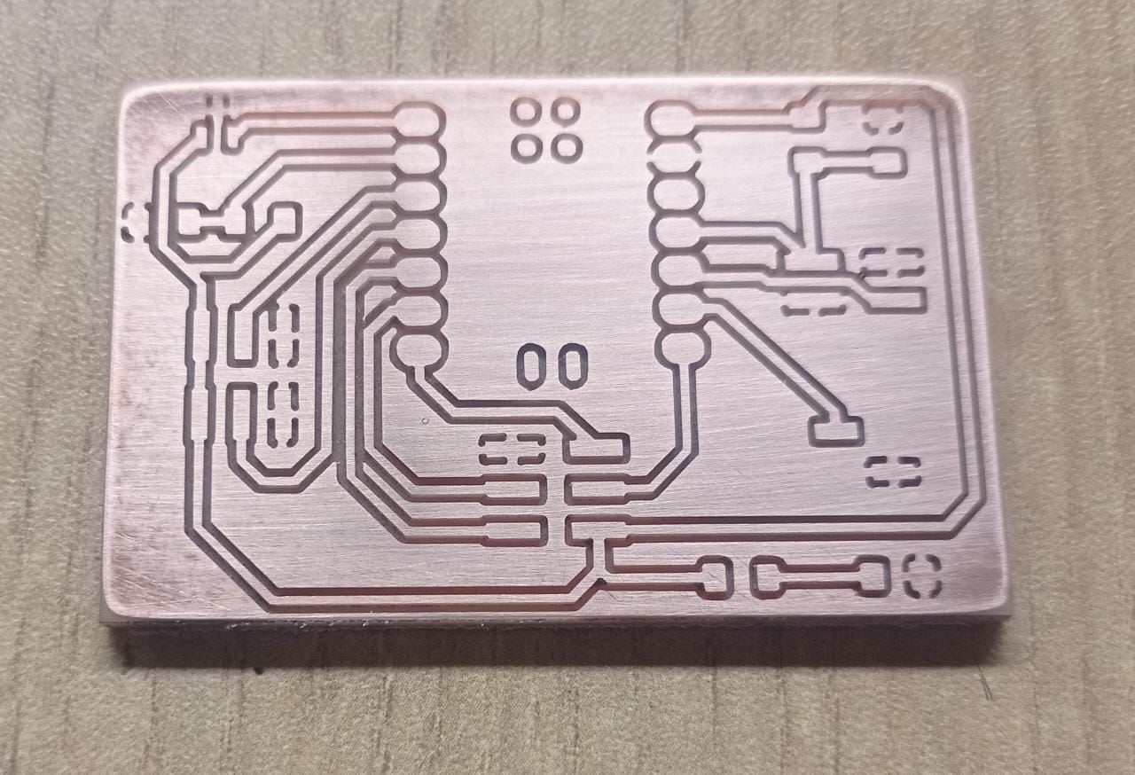
Figure N°10
We solder the components to the board.
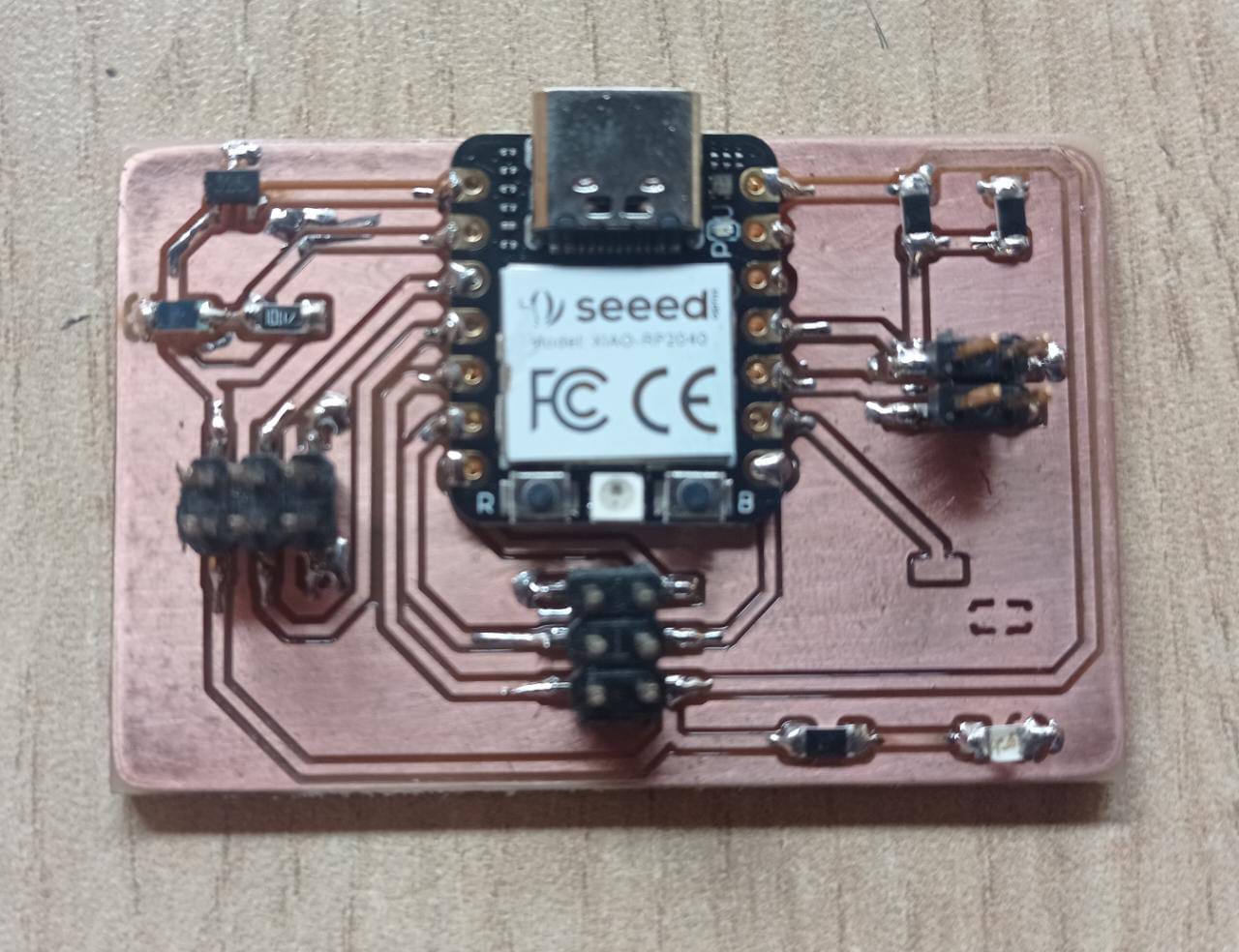
Figure N°11
And we verify that our design works correctly.

Figure N°12
For the group work we are going to test the sensors that we have previously described.
To read the value obtained from the hall effect sensor we will use a basic arduino script to read channel A0, convert it to digital and print it via Serial Monitor.
                      void setup() {
                        Serial.begin(9600);
                      }

                      void loop() {
                        int sensorValue = analogRead(A0);
                        Serial.println(sensorValue);
                        delay(50);
                      }
We see that the sensor works as expected.
Video N°1
We also did a test of this magnetic sensor with a multimeter where we appreciated the output voltage change based on the proximity of the magnet to the sensor.
Video N°2
For the light sensor we will use the same script, the only difference is that it will read the value of channel A1, in this case with less light the value tends to the highest and with less light the value decreases to the minimum.
Video N°3
To test a digital signal we are going to use a magnetic reed switch, this switch is activated when a magnet passes nearby and makes the circuit complete, to read this input we place one of the pins in an internal pull up and the other side of the sensor to ground.
                      int reed_switch = 2;
                      void setup() {
                        Serial.begin(9600);
                        pinMode(reed_switch, INPUT_PULLUP);
                      }
                      void loop() {
                        int state = digitalRead(reed_switch);
                        Serial.println(state);
                        delay(100);
                      }
We can see in the video that when the magnet approaches the value read is inverted.
Video N°4
In this test we test the pressure, we use a folded bond paper and the electrodes above and below it, we see how the intensity of the obtained signal changes depending on how much pressure we apply to it.
Video N°5
In this test we already have the electrodes under the plate of cat food, initially we only see the change when placing a hand inside it, we see in the video how inversely proportional how the signal drops to a minimum when the hand is covering the interior from the plate and increases when there is no longer anything interfering.
Video N°6
To improve the reading, a Kallman filter was added to stabilize the signal, eliminating part of the noise. Then the value obtained was changed in range with the Map function to see these changes more closely.
                      result = tx_rx();
                      result = map(result, 12000, 15000, 0, 1024);
                      float estimated_value = simpleKalmanFilter.updateEstimate(result);
                      result = map(estimated_value, 300, 6000, 0, 1024);
Additionally, an LCD screen was used to make a small animation of the cat bowl that fills up based on a simple IF conditional according to the increase in the value read.
                      lcd.setCursor(0,0);
                      lcd.print("    _  ******  _    ");
                      lcd.setCursor(0,1);
                      lcd.print("   / |*********| \  ");
                      lcd.setCursor(0,2);
                      lcd.print("  /  |*********|   \ ");
                      lcd.setCursor(0,3);
                      lcd.print(" |________________| ");
This will be the complete script.
                      #include
                        long result;
                        int analog_pin = 28;
                        int tx_pin = 4;

                        SimpleKalmanFilter simpleKalmanFilter(2, 2, 0.01);
                        #include
                        #include

                        LiquidCrystal_I2C lcd(0x27,20,4);

                        void setup() {
                        pinMode(tx_pin,OUTPUT);
                        Serial.begin(115200);
                          lcd.init();
                          lcd.backlight();
                        }


                        long tx_rx(){
                          int read_high;
                          int read_low;
                          int diff;
                          long int sum;
                          int N_samples = 100;

                          sum = 0;

                          for (int i = 0; i < N_samples; i++){
                           digitalWrite(tx_pin,HIGH);
                           read_high = analogRead(analog_pin);
                           delayMicroseconds(100);
                           digitalWrite(tx_pin,LOW);
                           read_low = analogRead(analog_pin);
                           diff = read_high - read_low;
                         sum += diff;
                         }
                          return sum;
                        }


                        void loop() {

                        result = tx_rx();
                        result = map(result, 12000, 15000, 0, 1024);

                        float estimated_value = simpleKalmanFilter.updateEstimate(result);
                        result = map(estimated_value, 300, 6000, 0, 1024);
                        Serial.println(estimated_value);

                        if (estimated_value>0 && estimated_value<=610)
                        {
                          lcd.setCursor(0,0);
                          lcd.print("    _          _    ");
                          lcd.setCursor(0,1);
                          lcd.print("   / |         | \  ");
                          lcd.setCursor(0,2);
                          lcd.print("  /  |_________|   \ ");
                          lcd.setCursor(0,3);
                          lcd.print(" |________________| ");
                          }

                        else if(estimated_value>610 && estimated_value<=653)
                        {

                          lcd.setCursor(0,0);
                          lcd.print("    _          _    ");
                          lcd.setCursor(0,1);
                          lcd.print("   / |         | \  ");
                          lcd.setCursor(0,2);
                          lcd.print("  /  |*********|   \ ");
                          lcd.setCursor(0,3);
                          lcd.print(" |________________| ");
                          }

                        else if(estimated_value>653 && estimated_value<=680)
                        {
                          lcd.setCursor(0,0);
                          lcd.print("    _          _    ");
                          lcd.setCursor(0,1);
                          lcd.print("   / |*********| \  ");
                          lcd.setCursor(0,2);
                          lcd.print("  /  |*********|   \ ");
                          lcd.setCursor(0,3);
                          lcd.print(" |________________| ");
                          }

                        else
                        {
                          lcd.setCursor(0,0);
                          lcd.print("    _  ******  _    ");
                          lcd.setCursor(0,1);
                          lcd.print("   / |*********| \  ");
                          lcd.setCursor(0,2);
                          lcd.print("  /  |*********|   \ ");
                          lcd.setCursor(0,3);
                          lcd.print(" |________________| ");
                          }

                        delay(1);
                        }
And here we can see a demo video.
Video N°7
The files created or used this week can be downloaded here:
| Input devices PCB - Kicad Files | Link |
| Input devices PCB - SVGs | Link |
| Script Analog Sensors | Link |
| Script Magnetic Reed Switch | Link |
| Script Step Response bowl cat | Link |