
For the group assignment we are going to work with microcontrollers of different architectures
The first module we will work with is the MKR1000, this is an arduino module that has embedded communication via WiFi.
We can see the pinout in Figure No. 1, this module is based on the microcontroller ATSAMW25, we can see the datasheet of this component in the following link
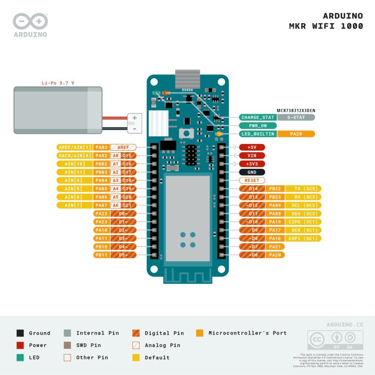
Figure N°1

Figure N°2
To start we will do the "hello world" of the microcontrollers, that is, turn on a led.
                      void setup() {
                        pinMode(LED_BUILTIN, OUTPUT);
                      }

                      void loop() {
                        digitalWrite(LED_BUILTIN, HIGH);
                        delay(1000);
                        digitalWrite(LED_BUILTIN, LOW);
                        delay(1000);
                      }
The script that we will use is the blink example and we will vary the on and off time, we can see the result in Video N°1. This example is obtained from here.
Video N°1
In the following script we will seek to control the lighting of the same led remotely, for this we will use the ability of the microcontroller to connect to a network, we will create a web server where each click will send the signal on or off to the led. This example is called "Wifi101 Simple Web Server " and can be obtained from here.
                        #include <SPI.h>
                        #include <WiFi101>

                        ///////please enter your sensitive data in the Secret tab/arduino_secrets.h
                        char ssid[] = SECRET_SSID;        // your network SSID (name)
                        char pass[] = SECRET_PASS;    // your network password (use for WPA, or use as key for WEP)
                        int keyIndex = 0;                 // your network key Index number (needed only for WEP)

                        int status = WL_IDLE_STATUS;
                        WiFiServer server(80);

                        void setup() {
                          Serial.begin(9600);      // initialize serial communication
                          pinMode(6, OUTPUT);      // set the LED pin mode

                          // check for the presence of the shield:
                          if (WiFi.status() == WL_NO_SHIELD) {
                            Serial.println("WiFi shield not present");
                            while (true);       // don't continue
                          }

                          // attempt to connect to WiFi network:
                          while ( status != WL_CONNECTED) {
                            Serial.print("Attempting to connect to Network named: ");
                            Serial.println(ssid);                   // print the network name (SSID);

                            // Connect to WPA/WPA2 network. Change this line if using open or WEP network:
                            status = WiFi.begin(ssid, pass);
                            // wait 10 seconds for connection:
                            delay(10000);
                          }
                          server.begin();                           // start the web server on port 80
                          printWiFiStatus();                        // you're connected now, so print out the status
                        }


                        void loop() {
                          WiFiClient client = server.available();   // listen for incoming clients

                          if (client) {                             // if you get a client,
                            Serial.println("new client");           // print a message out the serial port
                            String currentLine = "";                // make a String to hold incoming data from the client
                            while (client.connected()) {            // loop while the client's connected
                              if (client.available()) {             // if there's bytes to read from the client,
                                char c = client.read();             // read a byte, then
                                Serial.write(c);                    // print it out the serial monitor
                                if (c == '\n') {                    // if the byte is a newline character

                                  // if the current line is blank, you got two newline characters in a row.
                                  // that's the end of the client HTTP request, so send a response:
                                  if (currentLine.length() == 0) {
                                    // HTTP headers always start with a response code (e.g. HTTP/1.1 200 OK)
                                    // and a content-type so the client knows what's coming, then a blank line:
                                    client.println("HTTP/1.1 200 OK");
                                    client.println("Content-type:text/html");
                                    client.println();

                                    // the content of the HTTP response follows the header:
                                    client.print("Click here turn the LED on pin 9 on - Fab Academy 2023
");
                                    client.print("Click here turn the LED on pin 9 off - Fab Academy 2023
");

                                    // The HTTP response ends with another blank line:
                                    client.println();
                                    // break out of the while loop:
                                    break;
                                  }
                                  else {      // if you got a newline, then clear currentLine:
                                    currentLine = "";
                                  }
                                }
                                else if (c != '\r') {    // if you got anything else but a carriage return character,
                                  currentLine += c;      // add it to the end of the currentLine
                                }

                                // Check to see if the client request was "GET /H" or "GET /L":
                                if (currentLine.endsWith("GET /H")) {
                                  digitalWrite(6, HIGH);               // GET /H turns the LED on
                                }
                                if (currentLine.endsWith("GET /L")) {
                                  digitalWrite(6, LOW);                // GET /L turns the LED off
                                }
                              }
                            }
                            // close the connection:
                            client.stop();
                            Serial.println("client disonnected");
                          }
                        }

                        void printWiFiStatus() {
                          // print the SSID of the network you're attached to:
                          Serial.print("SSID: ");
                          Serial.println(WiFi.SSID());

                          // print your WiFi shield's IP address:
                          IPAddress ip = WiFi.localIP();
                          Serial.print("IP Address: ");
                          Serial.println(ip);

                          // print the received signal strength:
                          long rssi = WiFi.RSSI();
                          Serial.print("signal strength (RSSI):");
                          Serial.print(rssi);
                          Serial.println(" dBm");
                          // print where to go in a browser:
                          Serial.print("To see this page in action, open a browser to http://");
                          Serial.println(ip);
                        }
Some aspects to take into account in this application are the following:
- Make sure that the USB cable with which it is programmed has the capacity to provide enough current
- Measure the intensity of the signal with a script, since if the network is very far from the module there will be execution problems
We can see a demonstration of this script in Video N°2.
Video N°2
In order to vary the programming language, we will use the Raspberry Pi Pico module, this component can be programmed in different ways, for this example we will use MicroPython.
We can see the pinout in Figure No. 3, this module is based on the microcontroller RP2040, we can see the datasheet of this component in the following link
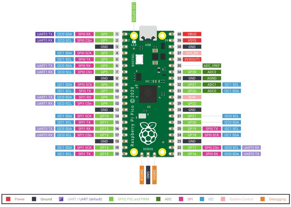
Figure N°3
To program this microcontroller it is necessary to use Thonny which is an integrated development environment for Python.
In order for the module to be recognized, it is necessary to copy a suitable UF2 format file into the archive files. The one that was used in this example is the following.
The steps to follow to program this microcontroller are the following:
In order to turn a led on and off, the Pin and Timer libraries must be imported, with the freq parameter we establish the blinking time. This example is called "Raspberry Pico Blink" and can be obtained from here.
                  from machine import Pin, Timer

                  led = Pin(25,Pin.OUT)
                  LED_state = True
                  tim = Timer()

                  def tick(timer):
                      global led, LED_state
                      LED_state = not LED_state
                      led.value(LED_state)

                  tim.init(freq=1, mode=Timer.PERIODIC, callback=tick)
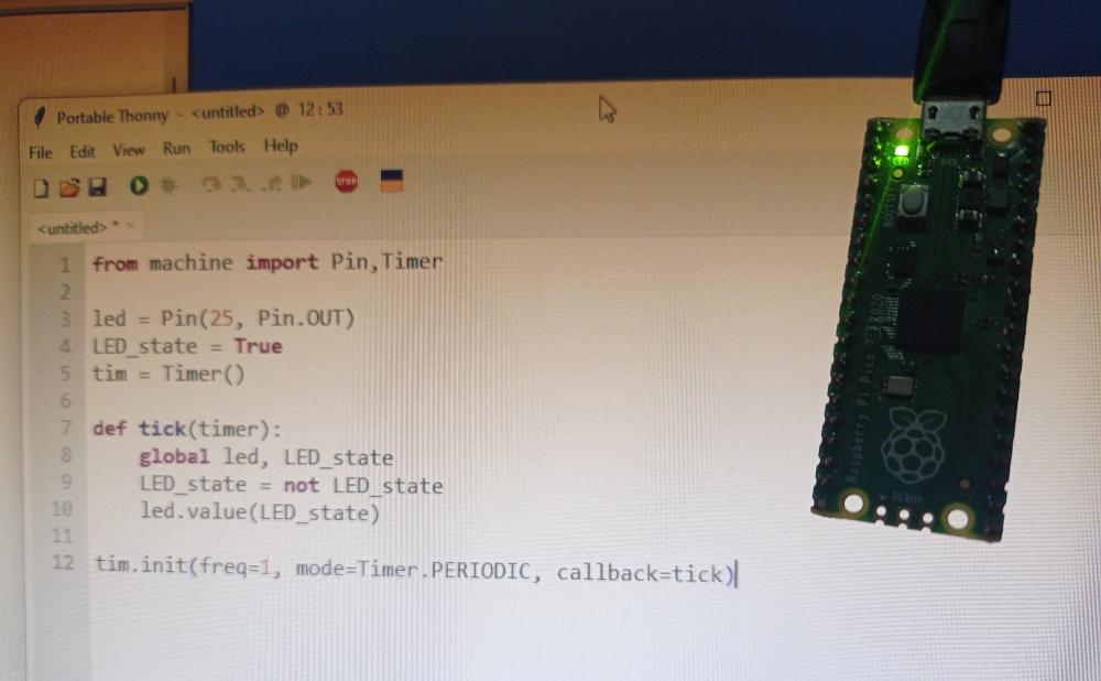
Figure N°4
We can see the demonstration with different blinking speeds in Video No.3
Video N°3
Also, we can use a breadboard to include more components to the exercises.
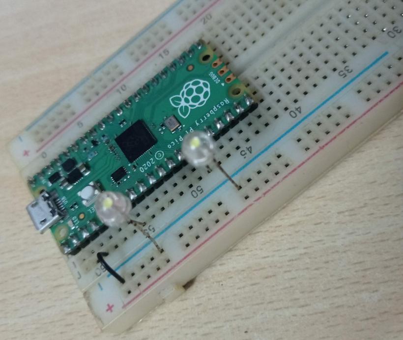
Figure N°5
In order to make 2 LEDs work simultaneously, we use the following script. This example is called "Alternate Blink" and can be obtained from here.
                  from machine import Pin,Timer

                  led1 = Pin(5, Pin.OUT)
                  led2 = Pin(10, Pin.OUT)

                  LED_state1 = True
                  LED_state2 = False

                  tim = Timer()

                  def tick(timer):
                      global led1, led2, LED_state1, LED_state2
                      LED_state1 = not LED_state1
                      LED_state2 = not LED_state2
                      led1.value(LED_state1)
                      led2.value(LED_state2)

                  tim.init(freq=10, mode=Timer.PERIODIC, callback=tick)
We can see the blinking of the 2 leds in Video No.4
Video N°4
Since the leds work as an output, now we will carry out an exercise where we will use an input (potentiometer) to later convert the value from analog to digital (ADC).
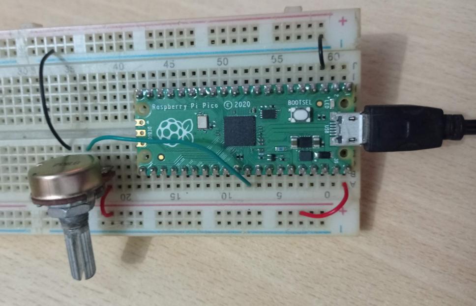
Figure N°6
Unlike the previous scripts, we will now import the utime library to generate a time delay. This example is called "Simple ADC Read" and can be obtained from here.
                  import machine
                  import utime

                  sensor_temp = machine.ADC(26)

                  while True:
                      reading = sensor_temp.read_u16()
                      print("ADC: ",reading)
                      utime.sleep(0.1)
We can see the value read by the ADC channel in Video No.5
Video N°5
Finally, we will use the Seed Studio XIAO RP2040 module.
We can see the pinout in Figure No. 7, this module is based on the microcontroller RP2040, we can see the datasheet of this component in the following link
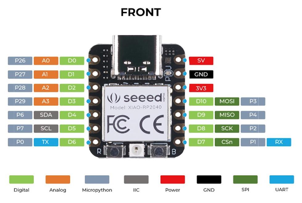
Figure N°7
The steps to follow to program this microcontroller are the following:

Figure N°8
As a first test we will use the classic blink, we can see a demonstration of the execution at different times on and off.
Video N°6
For this week's individual assignment we are going to review the datasheet of the microcontrollers that we are going to use and interacting with inputs / outputs and communicate them remotely.
We are going to do a comparison of the data sheets of the ATSAMW25 and the RP2040, you can see these files here and here.
| Microcontroller | - ATSAMW25 - | - RP2040 - |
| Operating Voltage (V) | 3.3 | 3.3 |
| Analog Input Pins | 7 | 5 |
| Digital I/O Pins | 8 | 30 |
| Flash Memory (KB) | 256 | 2000 |
| SRAM (KB) | 32 | 264 |
| Frequency (MHz) | 48 | 133 |
| Communication | IIC, SPI, USART | IIC, SPI, USART |
In the following exercises we will use the Seeed Studio XIAO Starter Kit, which has an Expansion board with which we can easily connect different components since it has specific connectors for each communication protocol.

Figure N°9
For the following exercise we will use a potentiometer as input and a servomotor as output.

Figure N°10
In the script for this exercise we read the value of the potentiometer and convert it to an angle from 0 to 180 so that it is reflected in the position of the servomotor. This example is called "Rotary Angle Sensor" and can be obtained from here.
                      #define ROTARY_ANGLE_SENSOR A0
                      #define LED 3  //the Grove - LED is connected to PWM pin D3 of Arduino
                      #define ADC_REF 5 //reference voltage of ADC is 5v.If the Vcc switch on the seeeduino
                                          //board switches to 3V3, the ADC_REF should be 3.3
                      #define GROVE_VCC 5 //VCC of the grove interface is normally 5v
                      #define FULL_ANGLE 300 //full value of the rotary angle is 300 degrees

                      void setup()
                      {
                          Serial.begin(9600);
                          pinMode(ROTARY_ANGLE_SENSOR, INPUT);
                          pinMode(LED,OUTPUT);
                      }

                      void loop()
                      {
                          float voltage;
                          int sensor_value = analogRead(ROTARY_ANGLE_SENSOR);
                          voltage = (float)sensor_value*ADC_REF/1023;
                          float degrees = (voltage*FULL_ANGLE)/GROVE_VCC;
                          Serial.println("The angle between the mark and the starting position:");
                          Serial.println(degrees);

                          int brightness;
                          brightness = map(degrees, 0, FULL_ANGLE, 0, 255);
                          analogWrite(LED,brightness);
                          delay(500);
                      }
We can see a demonstration of this in Video No.7
Video N°7
Next with the XIAO module, we will now use the Fab XIAO a design created by the Adrian Torres. You can see the documentation for this board here.
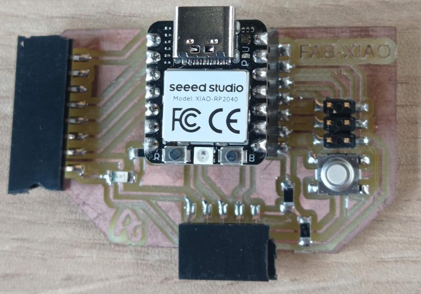
Figure N°11
Now we will use different components, as input the light sensor and the built-in neopixel led so that it shines based on the light level. This example is called "Neopixel" and can be obtained from here.
                      #include
                        int Power = 11;
                        int PIN  = 12;
                        #define NUMPIXELS 1
                        Adafruit_NeoPixel pixels(NUMPIXELS, PIN, NEO_GRB + NEO_KHZ800);

                        void setup()
                        {
                          pixels.begin();
                          pinMode(Power,OUTPUT);
                          digitalWrite(Power, HIGH);
                        }
                        void loop() {
                          pixels.clear();
                          pixels.setPixelColor(0, pixels.Color(15, 25, 205));
                          delay(400);
                          pixels.show();
                          pixels.clear();
                          pixels.setPixelColor(0, pixels.Color(103, 25, 205));
                          delay(400);
                          pixels.show();
                          pixels.clear();
                          pixels.setPixelColor(0, pixels.Color(233, 242, 205));
                          delay(400);
                          pixels.show();
                          pixels.clear();
                          pixels.setPixelColor(0, pixels.Color(233, 23, 23));
                          delay(400);
                          pixels.show();
                          pixels.clear();
                          pixels.setPixelColor(0, pixels.Color(12, 66, 101));
                          delay(400);
                          pixels.show();
                          delay(500);
                        }
We can see in video N°8, 2 examples of this program, changing the intensity of white color and changing from red light to blue.
Video N°8
Finally, we will use conductive copper tape to make a circuit that works with the XIAO module. The design that we will use is the one in Figure N°12 and can be downloaded here.
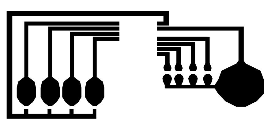
Figure N°12
We use Fab Modules to be able to make the cut with a plotter, it is important to mention that the cutting speed must be quite low, in our case 1cm/s worked and the force was 125 g.
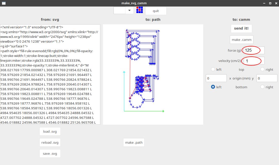
Figure N°13
We can see the cutting process on the plotter in Video No.9
Video N°9
The result is in Figure No.14
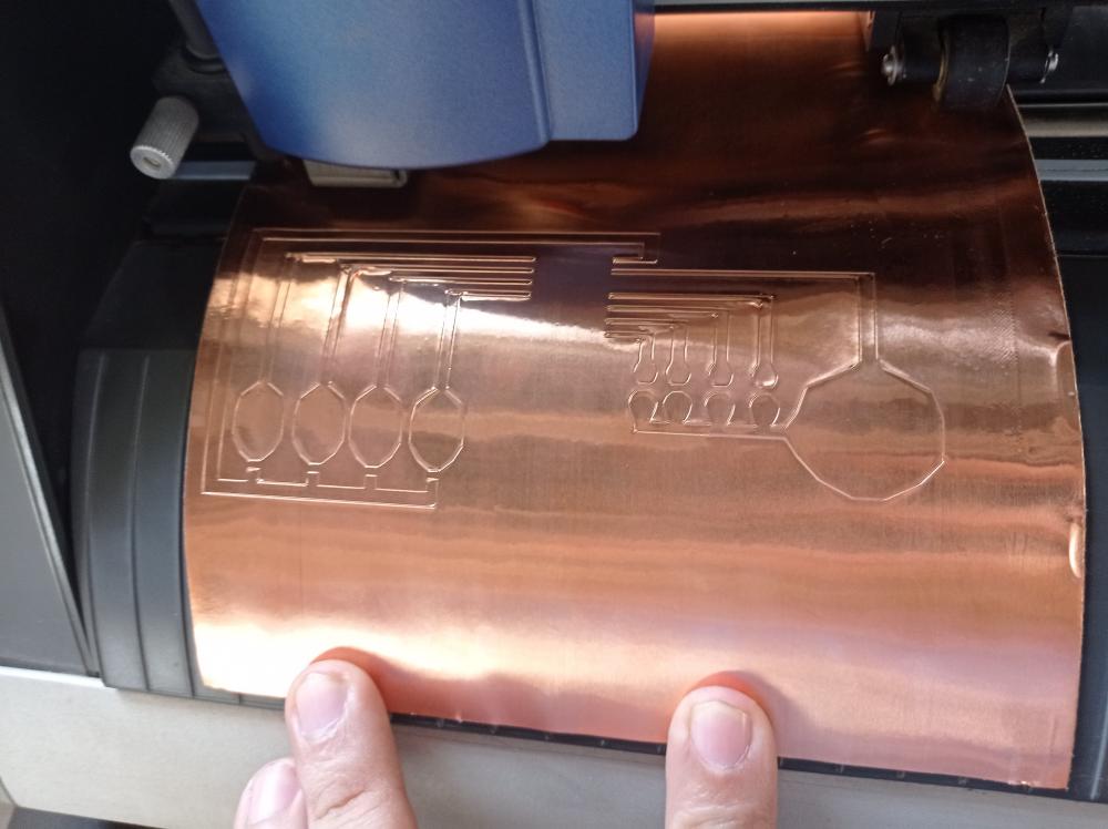
Figure N°14
Removing the material was quite cumbersome, if it is necessary to make sure that the cut was made homogeneously, otherwise there will be areas that rise at the time of cutting or areas that were only outlined but not cut, some fails can be seen in Figure No.15

Figure N°15
Once we were able to correctly remove the excess material, we used masking tape to make the transfer.
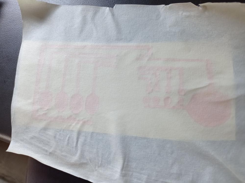
Figure N°16
This design was glued to an acrylic to then place the XIAO module.
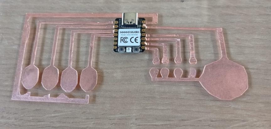
Figure N°17
We can see the design with the welded components in Figure No.18

Figure N°18
The first script will be a simple sequential blink of the 4 soldered leds.
In the Setup section of this script we define 4 pins as outputs and in the Loop section we activate each of them sequentially.
                      void setup() {
                        pinMode(1, OUTPUT);
                        pinMode(2, OUTPUT);
                        pinMode(4, OUTPUT);
                        pinMode(3, OUTPUT);
                      }

                      void loop() {
                        digitalWrite(1, HIGH);
                        digitalWrite(2, HIGH);
                        digitalWrite(4, HIGH);
                        digitalWrite(3, HIGH);
                        delay(1000);
                        digitalWrite(1, HIGH);
                        digitalWrite(2, LOW);
                        digitalWrite(4, LOW);
                        digitalWrite(3, LOW);
                        delay(1000);
                        digitalWrite(1, LOW);
                        digitalWrite(2, HIGH);
                        digitalWrite(4, LOW);
                        digitalWrite(3, LOW);
                        delay(1000);
                        digitalWrite(1, LOW);
                        digitalWrite(2, LOW);
                        digitalWrite(4, HIGH);
                        digitalWrite(3, LOW);
                        delay(1000);
                        digitalWrite(1, LOW);
                        digitalWrite(2, LOW);
                        digitalWrite(4, LOW);
                        digitalWrite(3, HIGH);
                        delay(1000);

                      }
The demonstration can be seen in video No.10
Video N°10
In the last script we will turn on the leds based on the change in the reading of the analog channels, this value is based on a voltage divider where we have a resistance of 1mega ohm and the resistance of a person. Within the Setup section we declare 4 outputs for the leds, in the Loop section we store the values read by the 4-pin digital analog channels and they are printed on the serial monitor. Subsequently, we evaluate the value obtained and if it is greater than a threshold, one of the 4 leds turns on.
                      void setup() {
                        pinMode(1, OUTPUT);
                      pinMode(2, OUTPUT);
                      pinMode(4, OUTPUT);
                      pinMode(3, OUTPUT);
                      Serial.begin(9600);
                    }

                    void loop() {
                      int sensorValue1 = analogRead(26);
                      int sensorValue2 = analogRead(27);
                      int sensorValue3 = analogRead(28);
                      int sensorValue4 = analogRead(29);

                      Serial.print(sensorValue1);
                      Serial.print(" ; ");
                      Serial.print(sensorValue2);
                      Serial.print(";");
                      Serial.print(sensorValue3);
                      Serial.print(" ; ");
                      Serial.println(sensorValue4);
                      delay(1);

                     if(sensorValue1<900){
                      digitalWrite(1,HIGH);
                      }
                     else{digitalWrite(1,LOW);}

                     if(sensorValue2<900){
                      digitalWrite(2,HIGH);
                      }
                     else{digitalWrite(2,LOW);}

                     if(sensorValue3<900){
                      digitalWrite(4,HIGH);
                      }
                     else{digitalWrite(4,LOW);}

                     if(sensorValue4<900){
                      digitalWrite(3,HIGH);
                      }
                     else{digitalWrite(3,LOW);}

                    }
In Video No.11 we can see that by placing one finger on the ground point and the other on an analog input we can activate one or more leds based on that change in voltage in the channels.
Video N°11
The files created and used this week can be downloaded here:
| Example Script 01 | Link |
| Example Script 02 | Link |
| Example Script 03 | Link |
| Example Script 04 | Link |
| Example Script 05 | Link |
| Example Script 06 | Link |
| Example Script 07 | Link |
| Script 01 | Link |
| Script 02 | Link |