
We were asked to start thinking and sketching a final project that has our personal brand, and that solves a problem. Immediately after class, I heard the meowing of my cats asking for food, and I thought of the following proposal.
As an owner of adult cats, I know firsthand that the health of our pets is sometimes a mystery as they don't have a direct way to communicate a nuisance, but several signs can give us clues that something is wrong with them. In the case of cats, one of the first warning signs is that they do not eat. When one is constantly serving food on their plate, it is not easy to discern this.
Among the existing products on the market, there are many Smart feeders (Figure 1A) or DIY projects (Figure 1B) of the exact nature, but in general, they focus on giving food at a specific time and with exact portions but never monitoring food consumption.
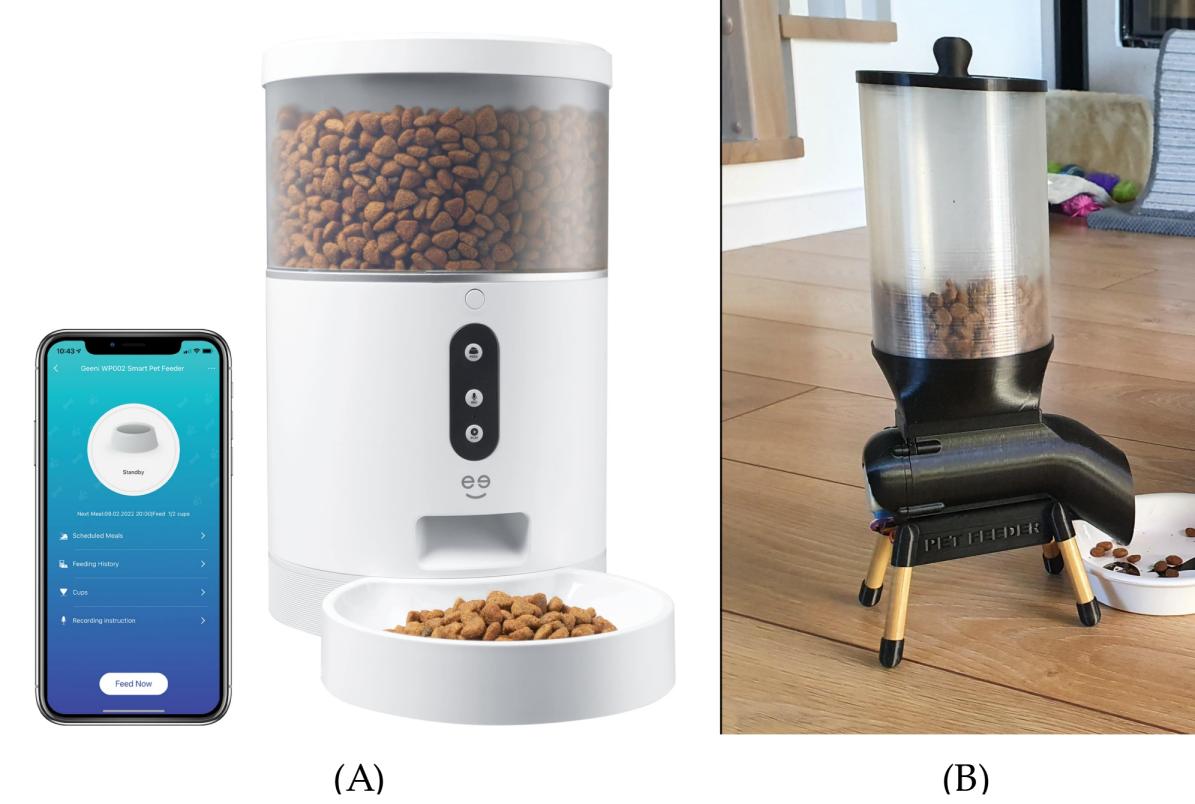
Figure N°1: Cat feeders (A) Commercial product (B) DIY project
For this reason, the first part of this proposal is focused not only on giving the correct portion of food at the right time but also on monitoring the state of the dish monitoring the number of grams consumed per day because if we have a record of this parameter, we can know if there is an appetite problem in the pet that can be an indication of diseases.
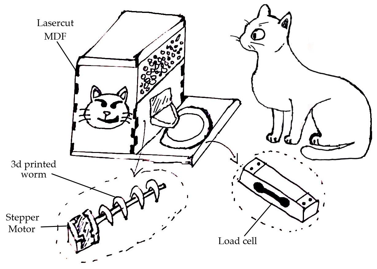
Figure N°2: Sketch of the first part of the final project
To measure the state of the dish we will use a load cell, to move the food a stepper motor with a 3D-printed worm, all in a casing made of laser-cut mdf.
For the second part, the matter is a little more complicated; another vital sign in cats is the heart rate; an adequate bpm range according to the minimums age, and values outside that range would denote a health problem.
The gold standard with which veterinarians measure this parameter is using a stethoscope. In the case of owners, they must put their hand on their cat's chest, count how many pulsations they find in 15 seconds, and then multiply that value by 4.
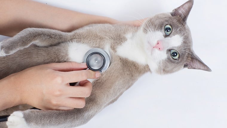
Figure N°3: Measuring heart rate in cats
For this reason, the idea is to monitor this parameter while the cat is resting; as we know that cats love boxes, the idea is to create a rounded cube with cardboard and MDF that has all the necessary components for this measurement at the bottom.
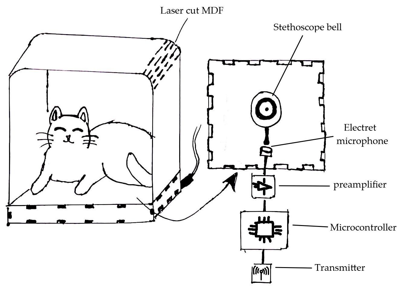
Figure N°4: Sketch of the second part of the final project
The main element is the bell of a stethoscope, adapting the sound output tube to an electret microphone with a preamplifier to send the signal to a microcontroller and later send it via WiFi to a server. Subsequently, this signal must be cleaned and processed to find the amplitude peaks and, therefore, the bits per minute.
This proposal has the approval of potential users (Figure 5). See you next week.
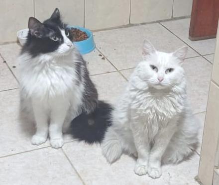
Figure N°5: The potential users
The next input that we will use will be the Step Response, it is a sensor that makes use of two conductive copper tapes. This can be used to calculate the amount of material they have in the middle of both, in our case we will evaluate the amount of food that is inside a cat bowl.
This design is based on documented work by Adrian Torres. In this design, one of the copper tapes is used as a TX electrode, a series of pulses is sent that allows more or less that series of pulses to pass to the other RX tape depending on what is in between, this other electrode will be connected between two resistors, one pull-up and one pull-down of 1M and an analog input.
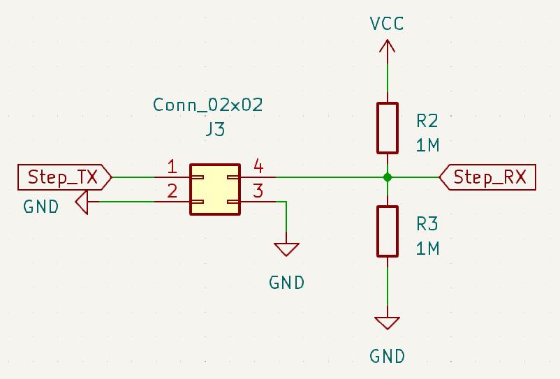
Figure N°6
In this test we test the pressure, we use a folded bond paper and the electrodes above and below it, we see how the intensity of the obtained signal changes depending on how much pressure we apply to it.
Video N°1
In this test we already have the electrodes under the plate of cat food, initially we only see the change when placing a hand inside it, we see in the video how inversely proportional how the signal drops to a minimum when the hand is covering the interior from the plate and increases when there is no longer anything interfering.
Video N°2
To improve the reading, a Kallman filter was added to stabilize the signal, eliminating part of the noise. Then the value obtained was changed in range with the Map function to see these changes more closely.
                      result = tx_rx();
                      result = map(result, 12000, 15000, 0, 1024);
                      float estimated_value = simpleKalmanFilter.updateEstimate(result);
                      result = map(estimated_value, 300, 6000, 0, 1024);
Additionally, an LCD screen was used to make a small animation of the cat bowl that fills up based on a simple IF conditional according to the increase in the value read.
                      lcd.setCursor(0,0);
                      lcd.print("    _  ******  _    ");
                      lcd.setCursor(0,1);
                      lcd.print("   / |*********| \  ");
                      lcd.setCursor(0,2);
                      lcd.print("  /  |*********|   \ ");
                      lcd.setCursor(0,3);
                      lcd.print(" |________________| ");
This will be the complete script.
                      #include
                        long result;
                        int analog_pin = 28;
                        int tx_pin = 4;

                        SimpleKalmanFilter simpleKalmanFilter(2, 2, 0.01);
                        #include
                        #include

                        LiquidCrystal_I2C lcd(0x27,20,4);

                        void setup() {
                        pinMode(tx_pin,OUTPUT);
                        Serial.begin(115200);
                          lcd.init();
                          lcd.backlight();
                        }


                        long tx_rx(){
                          int read_high;
                          int read_low;
                          int diff;
                          long int sum;
                          int N_samples = 100;

                          sum = 0;

                          for (int i = 0; i < N_samples; i++){
                           digitalWrite(tx_pin,HIGH);
                           read_high = analogRead(analog_pin);
                           delayMicroseconds(100);
                           digitalWrite(tx_pin,LOW);
                           read_low = analogRead(analog_pin);
                           diff = read_high - read_low;
                         sum += diff;
                         }
                          return sum;
                        }


                        void loop() {

                        result = tx_rx();
                        result = map(result, 12000, 15000, 0, 1024);

                        float estimated_value = simpleKalmanFilter.updateEstimate(result);
                        result = map(estimated_value, 300, 6000, 0, 1024);
                        Serial.println(estimated_value);

                        if (estimated_value>0 && estimated_value<=610)
                        {
                          lcd.setCursor(0,0);
                          lcd.print("    _          _    ");
                          lcd.setCursor(0,1);
                          lcd.print("   / |         | \  ");
                          lcd.setCursor(0,2);
                          lcd.print("  /  |_________|   \ ");
                          lcd.setCursor(0,3);
                          lcd.print(" |________________| ");
                          }

                        else if(estimated_value>610 && estimated_value<=653)
                        {

                          lcd.setCursor(0,0);
                          lcd.print("    _          _    ");
                          lcd.setCursor(0,1);
                          lcd.print("   / |         | \  ");
                          lcd.setCursor(0,2);
                          lcd.print("  /  |*********|   \ ");
                          lcd.setCursor(0,3);
                          lcd.print(" |________________| ");
                          }

                        else if(estimated_value>653 && estimated_value<=680)
                        {
                          lcd.setCursor(0,0);
                          lcd.print("    _          _    ");
                          lcd.setCursor(0,1);
                          lcd.print("   / |*********| \  ");
                          lcd.setCursor(0,2);
                          lcd.print("  /  |*********|   \ ");
                          lcd.setCursor(0,3);
                          lcd.print(" |________________| ");
                          }

                        else
                        {
                          lcd.setCursor(0,0);
                          lcd.print("    _  ******  _    ");
                          lcd.setCursor(0,1);
                          lcd.print("   / |*********| \  ");
                          lcd.setCursor(0,2);
                          lcd.print("  /  |*********|   \ ");
                          lcd.setCursor(0,3);
                          lcd.print(" |________________| ");
                          }

                        delay(1);
                        }
And here we can see a demo video.
Video N°3
This week's assignment is to write an application that interacts with a user with input and/or output devices on one of the boards that have been created.
For this task we will use one of the boards created in week 13 where an XIAO ESP32 is used.
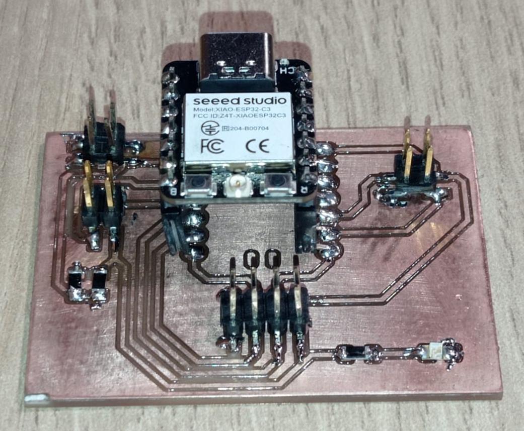
Figure N°7
We are going to create a graphic interface that reads the value of a potentiometer and based on the value obtained has an image that changes, since our final project is the automatic cat feeder, the image we will use will be an empty bowl to a full one.
The language that we will use to program our interface will be Python together with the Tkinter library, we will use chatgpt to give us a basic script that we will modify.
The prompt that was used was the following: "I want to make a graphical interface in python in which I have an image that changes depending on the value read by pyserial"
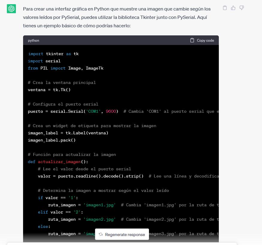
Figure N°8
The result obtained was the following:
import tkinter as tk
import serial
from PIL import Image, ImageTk

# Crea la ventana principal
ventana = tk.Tk()

# Configura el puerto serial
puerto = serial.Serial('COM20', 9600)  # Cambia 'COM1' al puerto serial que estés utilizando

# Crea un widget de etiqueta para mostrar la imagen
imagen_label = tk.Label(ventana)
imagen_label.pack()

# Función para actualizar la imagen
def actualizar_imagen():
    # Lee el valor desde el puerto serial
    valor = puerto.readline().decode().strip()  # Lee una línea y decodifica los bytes a cadena

    # Determina la imagen a mostrar según el valor leído
    if valor == '1':
        ruta_imagen = 'imagen1.jpg'  # Cambia 'imagen1.jpg' por la ruta de tu primera imagen
    elif valor == '2':
        ruta_imagen = 'imagen2.jpg'  # Cambia 'imagen2.jpg' por la ruta de tu segunda imagen
    else:
        ruta_imagen = 'imagen3.jpg'  # Cambia 'imagen3.jpg' por la ruta de tu tercera imagen

    # Carga la imagen y la muestra en el widget de etiqueta
    imagen = Image.open(ruta_imagen)
    imagen = imagen.resize((300, 300))  # Cambia el tamaño de la imagen según tus necesidades
    imagen_tk = ImageTk.PhotoImage(imagen)
    imagen_label.configure(image=imagen_tk)
    imagen_label.image = imagen_tk  # Actualiza la referencia a la imagen para evitar que sea eliminada por el recolector de basura

    # Programa la próxima actualización de la imagen
    ventana.after(1000, actualizar_imagen)  # Cambia el intervalo de actualización según tus necesidades (en milisegundos)

# Inicia la actualización de la imagen
actualizar_imagen()

# Ejecuta el bucle principal de la interfaz gráfica
ventana.mainloop()
From this we will make a small change, we will increase one more option in the conditional so that there are 4 images depending on the value obtained.
    if valor == '1':
        ruta_imagen = 'imagen1.jpg'
    elif valor == '2':
        ruta_imagen = 'imagen2.jpg'
    elif valor == '3':
        ruta_imagen = 'imagen3.jpg'
    else:
        ruta_imagen = 'imagen0.jpg'
Additionally, the image refresh time was also changed to be 10 milliseconds and the image size was changed to (960,540).
Then another request was made for an arduino script that works with the interface, the prompt used was the following: "what would be the arduino code to send the signal through the serial port"
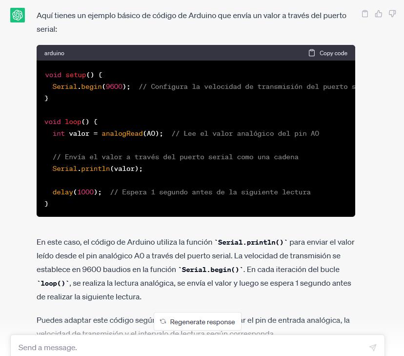
Figure N°9
The result obtained was the following:
void setup() {
  Serial.begin(9600);  // Configura la velocidad de transmisión del puerto serial a 9600 baudios
}

void loop() {
  int valor = analogRead(A0);  // Lee el valor analógico del pin A0

  // Envía el valor a través del puerto serial como una cadena
  if (valor < 512) {
    Serial.println('1');
  } else {
    Serial.println('2');
  }

  delay(1000);  // Espera 1 segundo antes de la siguiente lectura
}
Here the result was quite simple, we make changes in the conditional since when using this module we have a 12-bit ADC, that is, the values go from 0 to 4095.
if (valor <= 4095 && valor>=3072) {
  Serial.println('3');
}
else if (valor < 3072 && valor>=2048) {
  Serial.println('2');
}
else if (valor < 2048 && valor>=1024) {
  Serial.println('1');
}
else {
  Serial.println('0');
}
delay(100);
To design the images of the interface, Blender was used, starting from a basic figure called a torus using the edition mode, a bowl for pets was created.
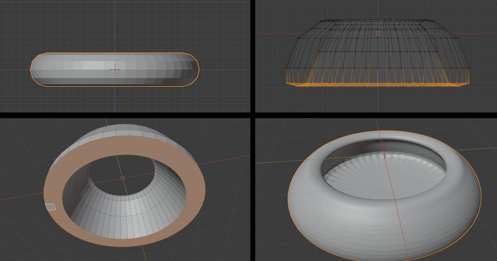
Figure N°10
Basic figures representing the small cookies were also created and they filled the bowl to create these images.
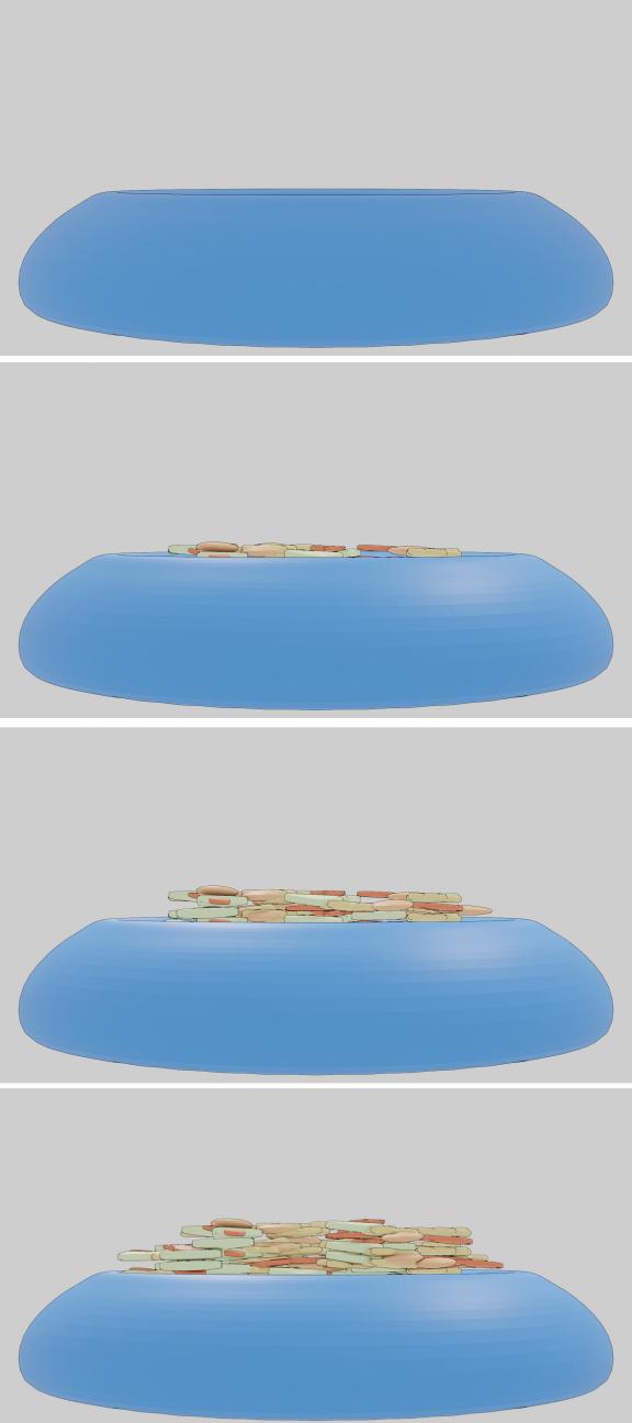
Figure N°11
We uploaded the arduino code to our XIAO ESP32 and the python script was executed from the Geany IDE.
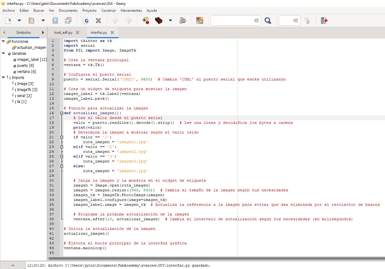
Figure N°12
We see a demonstration of the integrated elements.
Video N°4
This week's assignment is about wildcard and we are going to make a structure that will serve us for our final project based on composites.
We will start with a free design of a cat with its paws. The design is from Thingiverse, you can download it here.
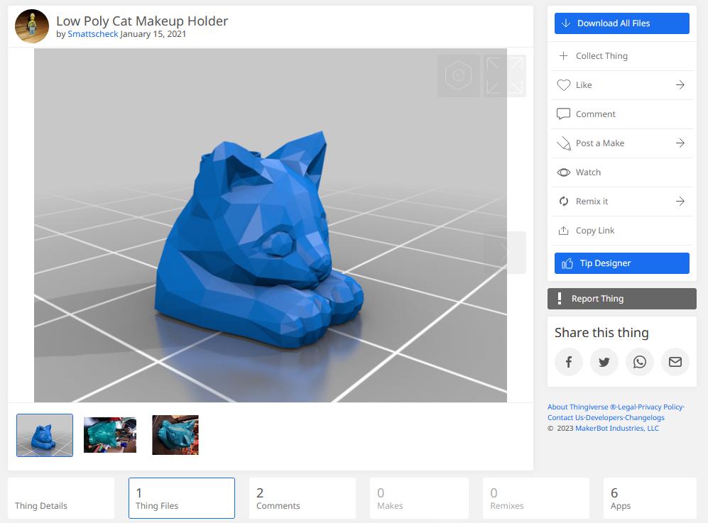
Figure N°13
In Blender changes were made to create a separation between its legs, the idea is that there is enough space to put a plate of food there and we export in .STL format.
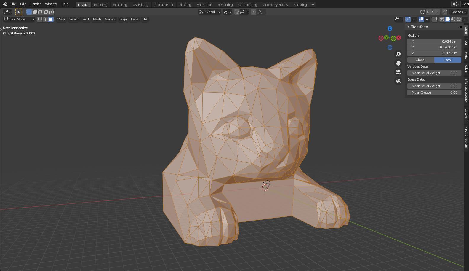
Figure N°14
We use the page Papercraft-maker to make a display to create it papercraft style, we choose a sheet size of A3 so that the approximate dimensions are a 30cm cube.
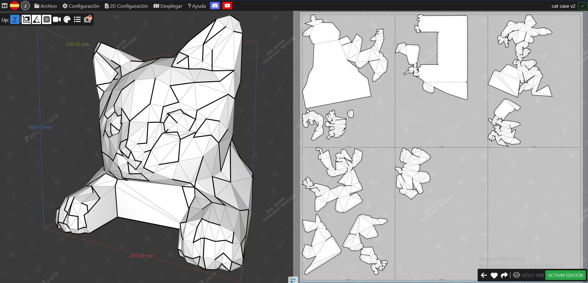
Figure N°15
The first cutting tests with cardboard are made.
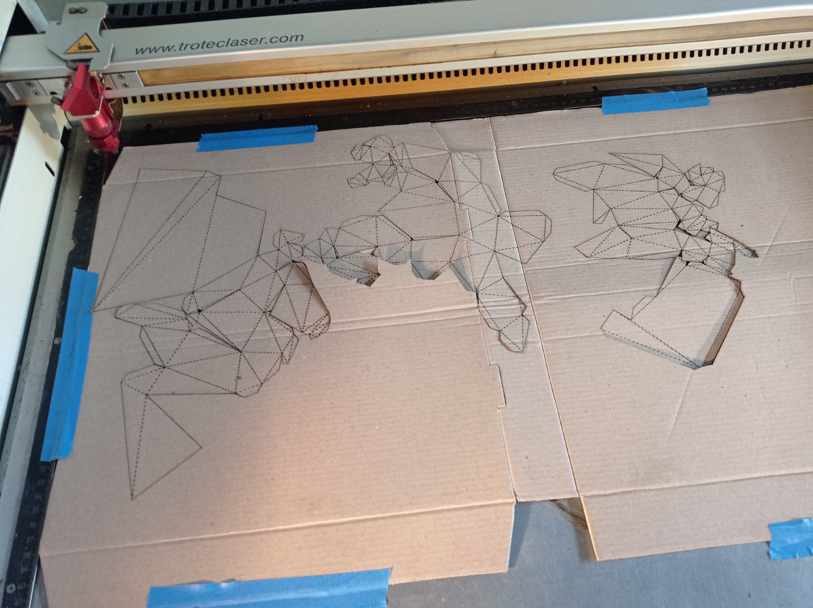
Figure N°16
It is necessary to modulate the speed of the cut since by having a slow speed you end up burning more than cutting the cardboard and when folding it you end up undoing the material.
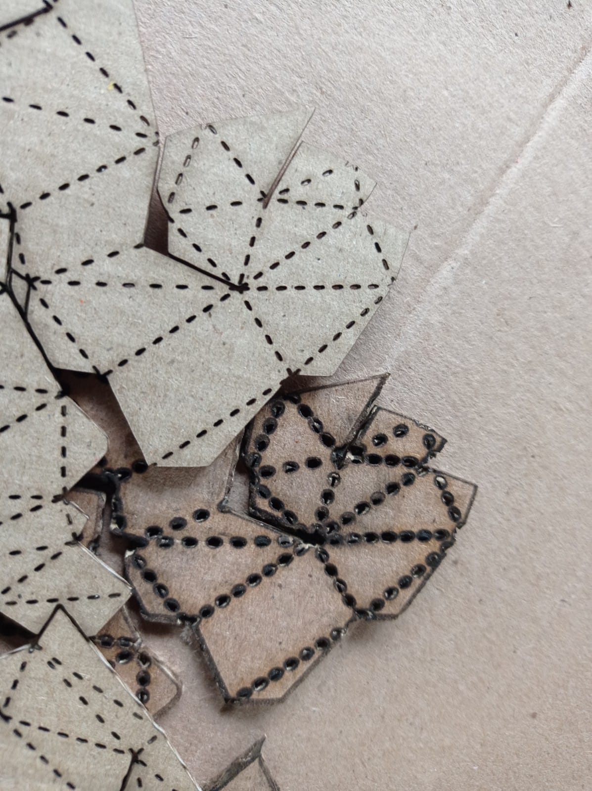
Figure N°17
After several tests these are the ideal settings for cutting cardboard.
| Cardboard__ Cut Results __ | |
| Power | 25 - 30 |
| Speed | 1.5 |
Table N°1
We start gluing the parts with school glue.
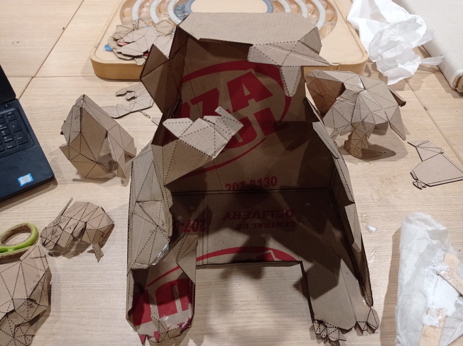
Figure N°18
Sticking it with school glue is usually quite a slow and tedious process so that the parts don't end up moving.
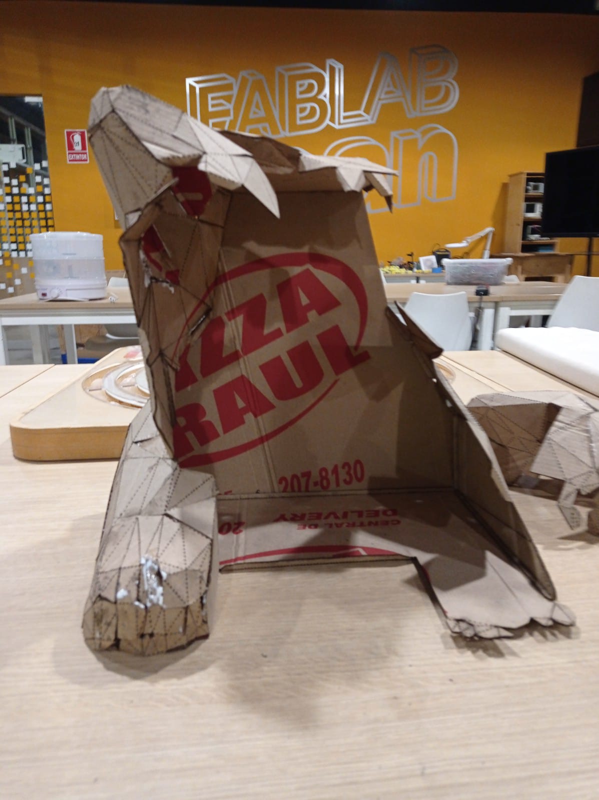
Figure N°19
The gluing material was changed to super glue, with that the process sped up a lot and we see how the pieces add up.
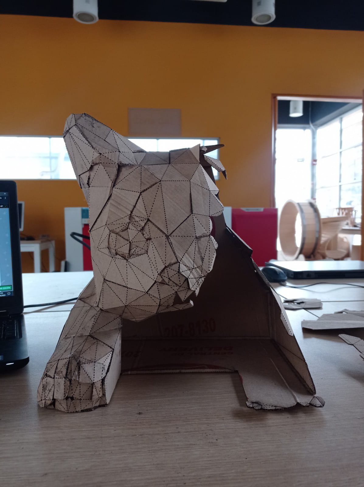
Figure N°20
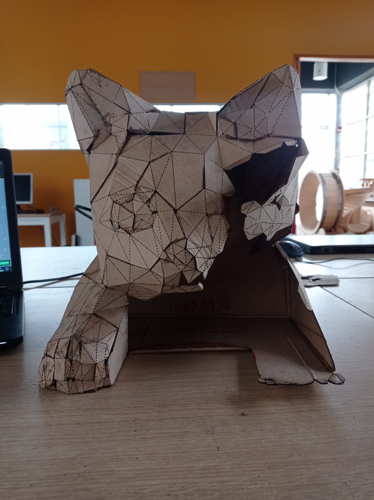
Figure N°21
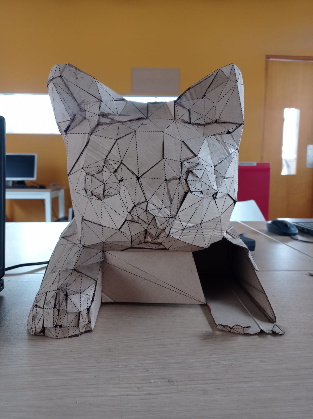
Figure N°22
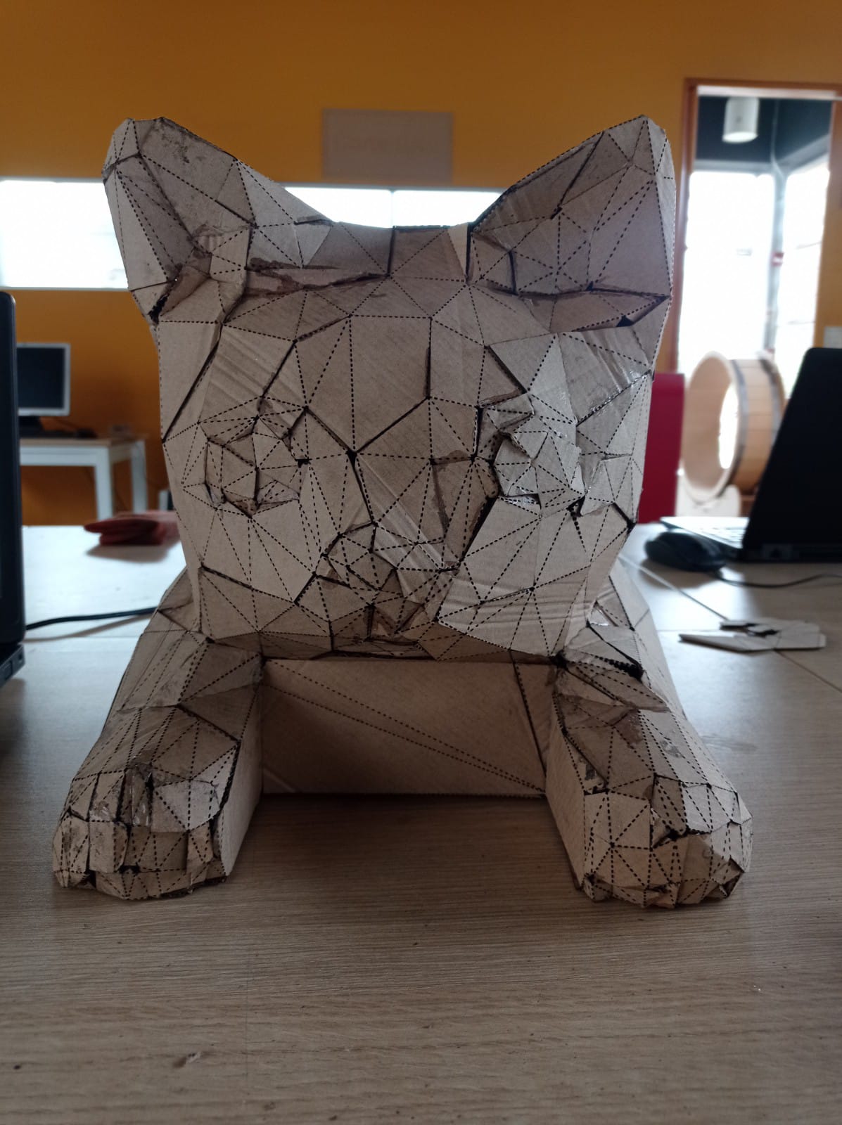
Figure N°23
And this is what all the pieces look like together, a pretty decent product
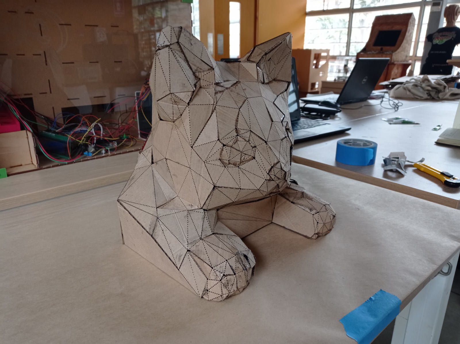
Figure N°24
Now to make the composite we will use fabric to cover the cardboard, we will use the same design to make the cuts.
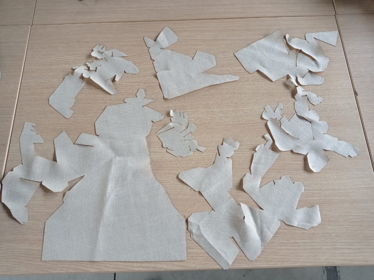
Figure N°25
The proper settings for cutting this fabric are as follows.
| Fabric__ Cut Results __ | |
| Power | 10 - 15 |
| Speed | 1.5 |
Table N°2
The resin that we are going to use is the same one described in week 12.
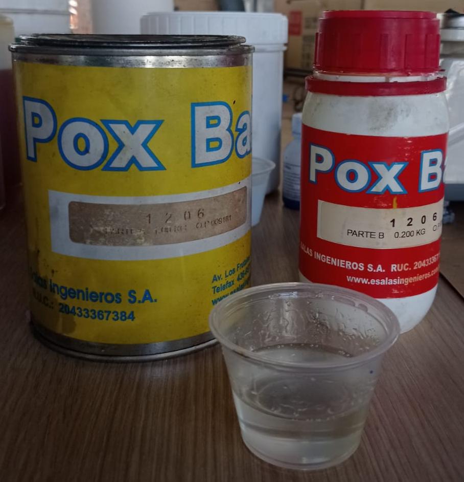
Figure N°26
Therefore, the way to mix this material is as follows:
| Material | Epoxy Resin |
| Mixing Ratio | 1:5 |
| Example | 10 ml(A) : 50 ml(B) |
Table N°3
Each piece of cloth is dipped in the mixture and glued on top of the cardboard.
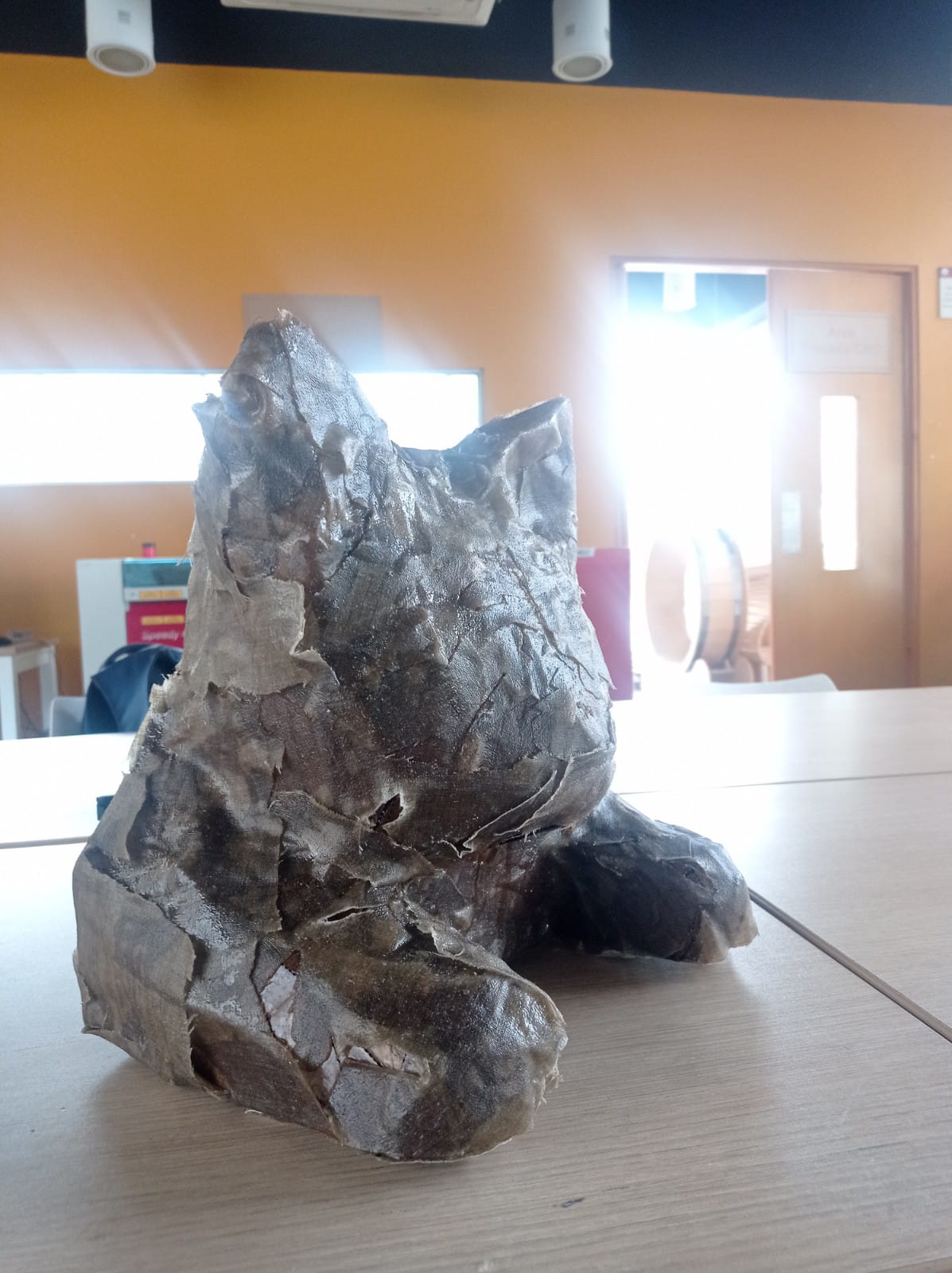
Figure N°27
When the resin is dry, quick-drying drywall putty is added to sand the piece down.

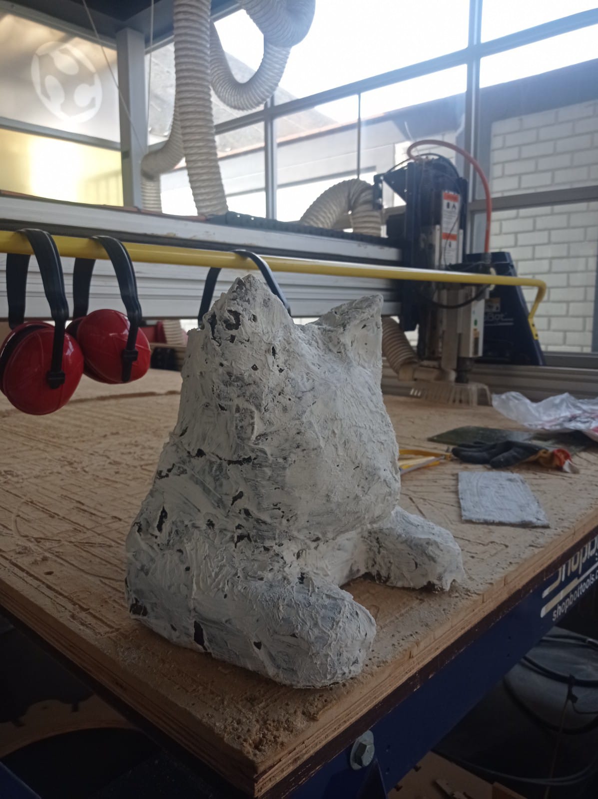
Figure N°28
Two passes of putty were made on the structure.
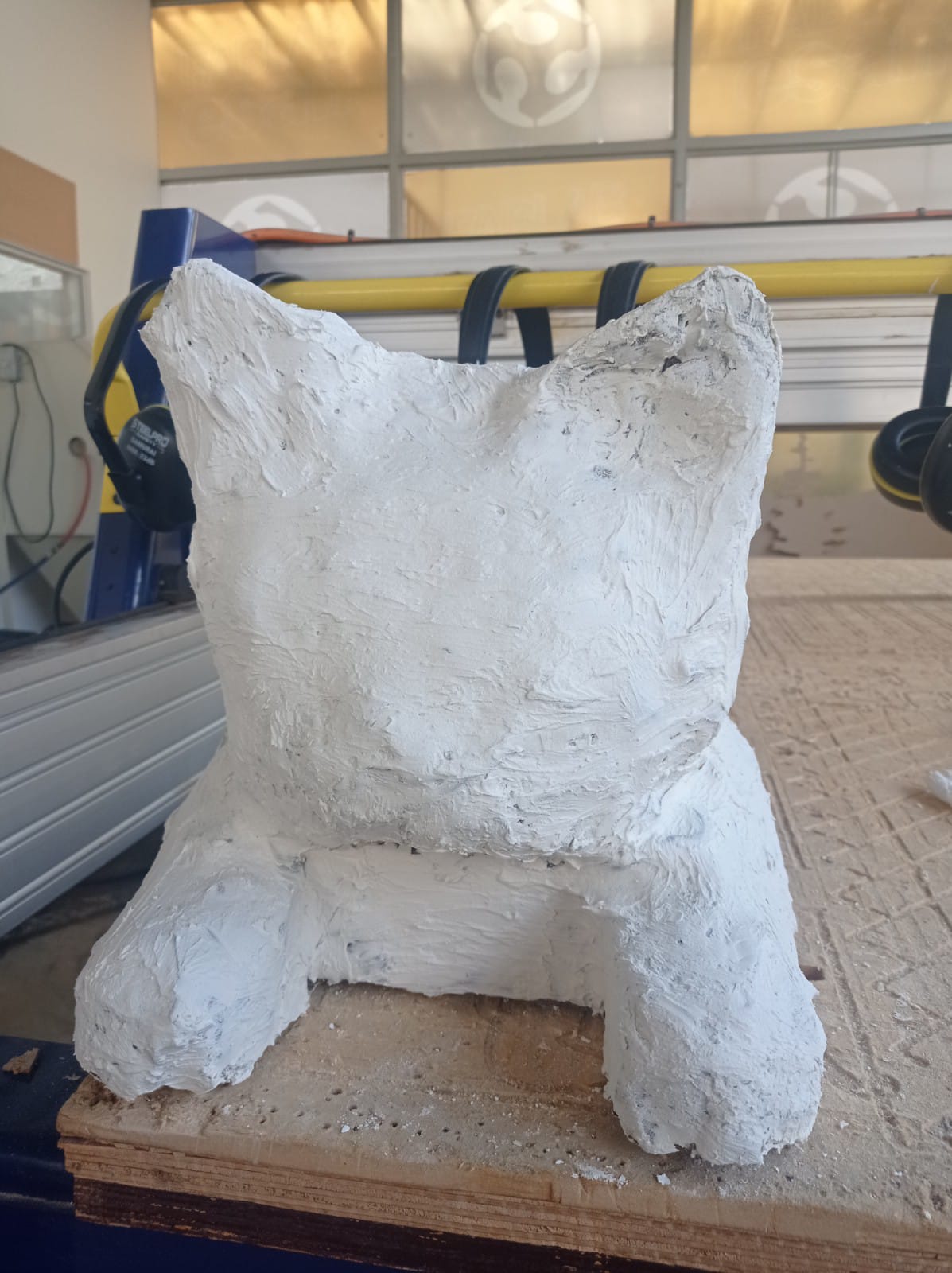
Figure N°29
The entire piece was then sanded and painted, finishing with a better finish.
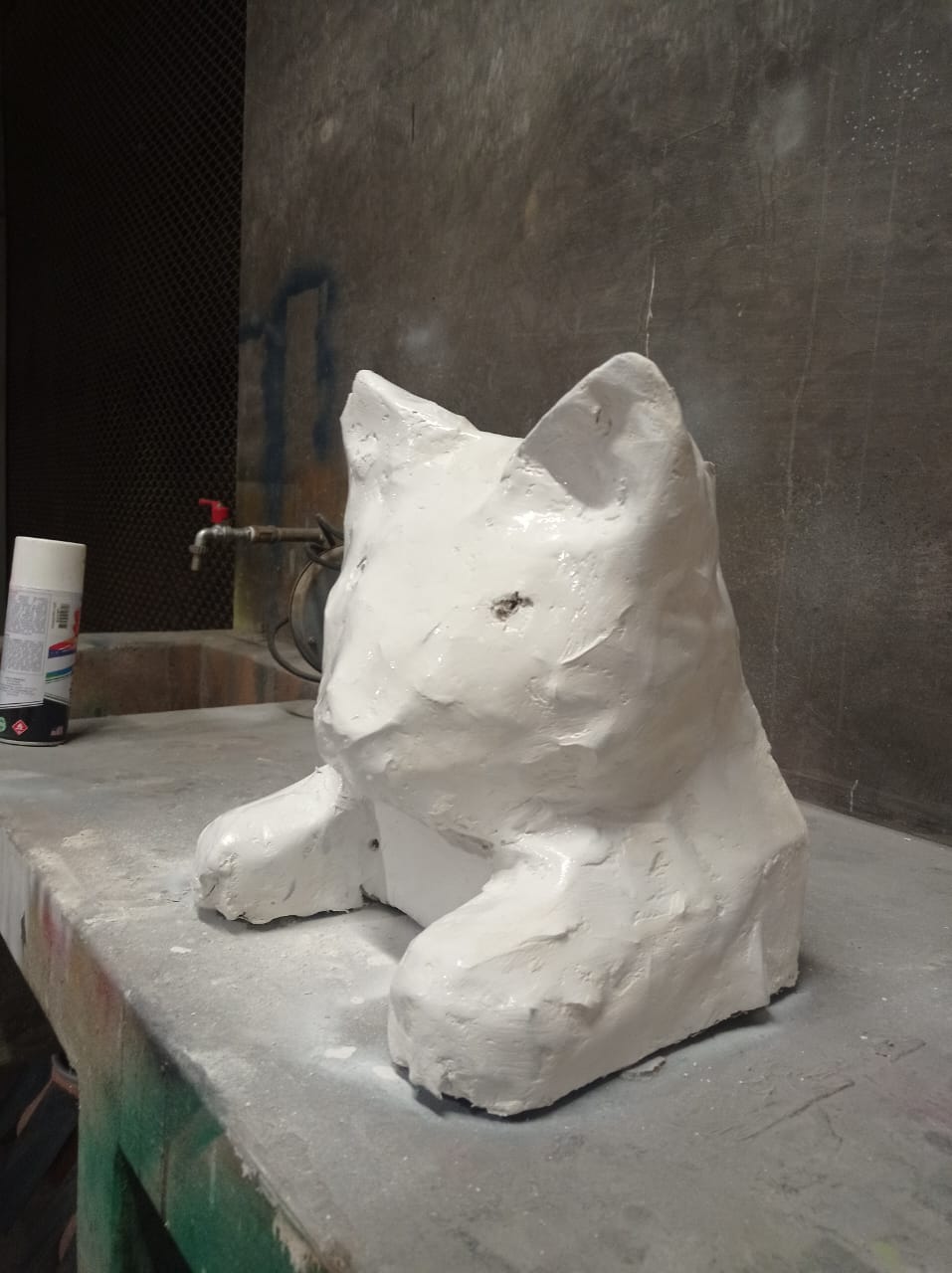
Figure N°30
Finally we obtained a completely solid structure.
Video N°5
To integrate all the internal parts of the final project, an internal structure has been designed to print in FDM.
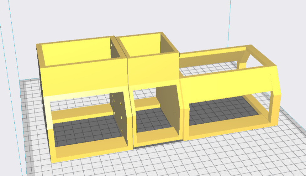
Figure N°31
This was printed on a Guider II.
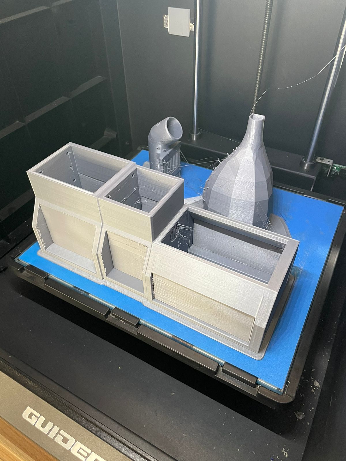
Figure N°32
This is what the integrated parts look like.
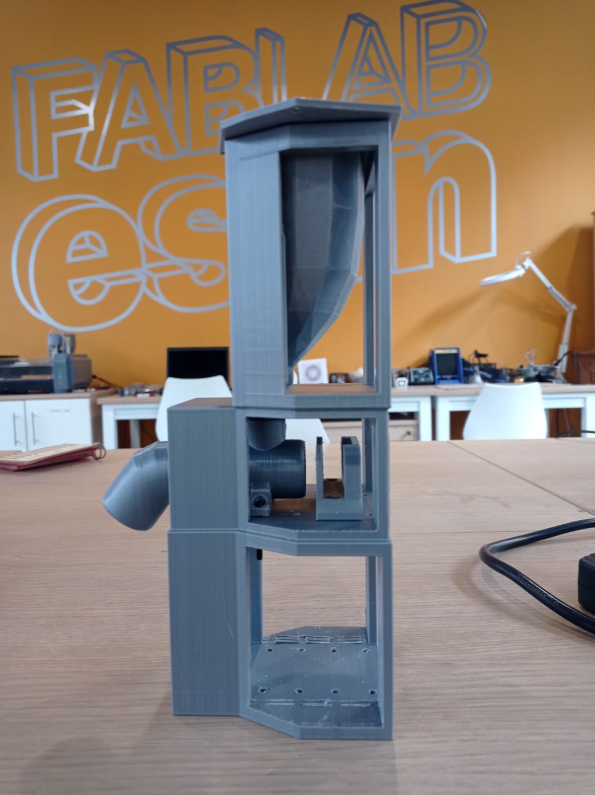
Figure N°33
Above the container for the cookies, the second space the actuator and the bottom space for the PCBs.
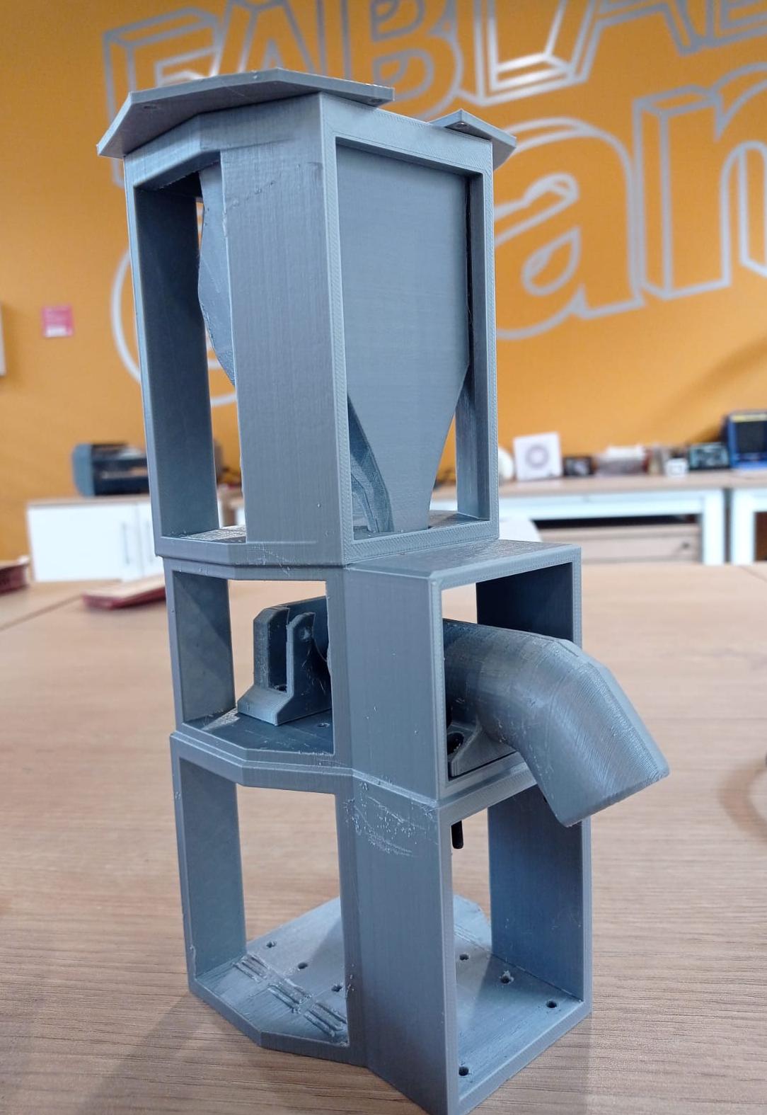
Figure N°34
For the worm that displaces the food, a Form3 printer was used.
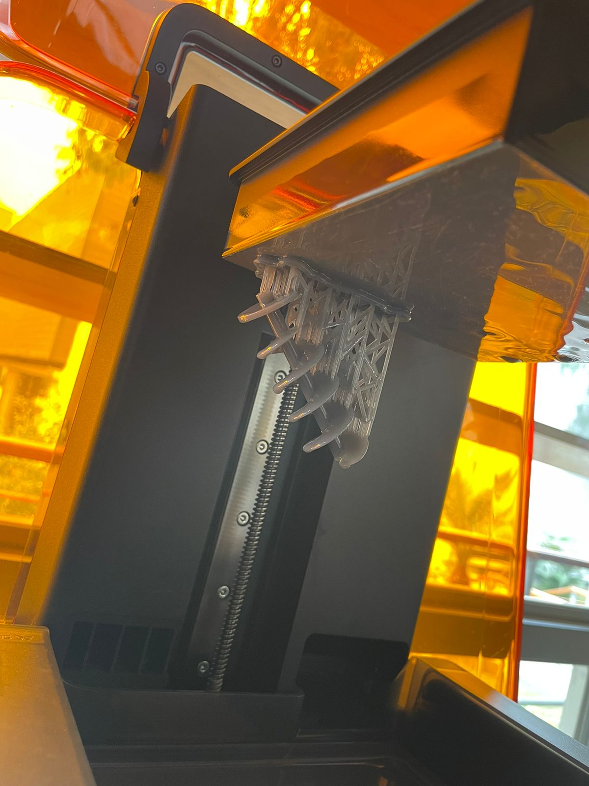
Figure N°35
We see the great details of this piece.
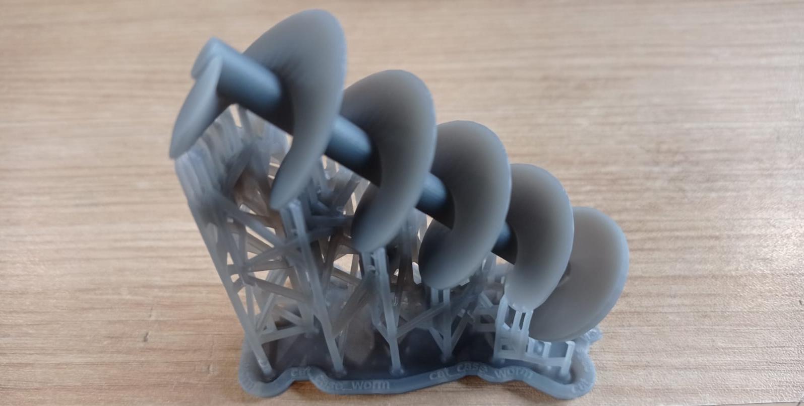
Figure N°36
This is attached to the FDM printed part and the stepper motor.
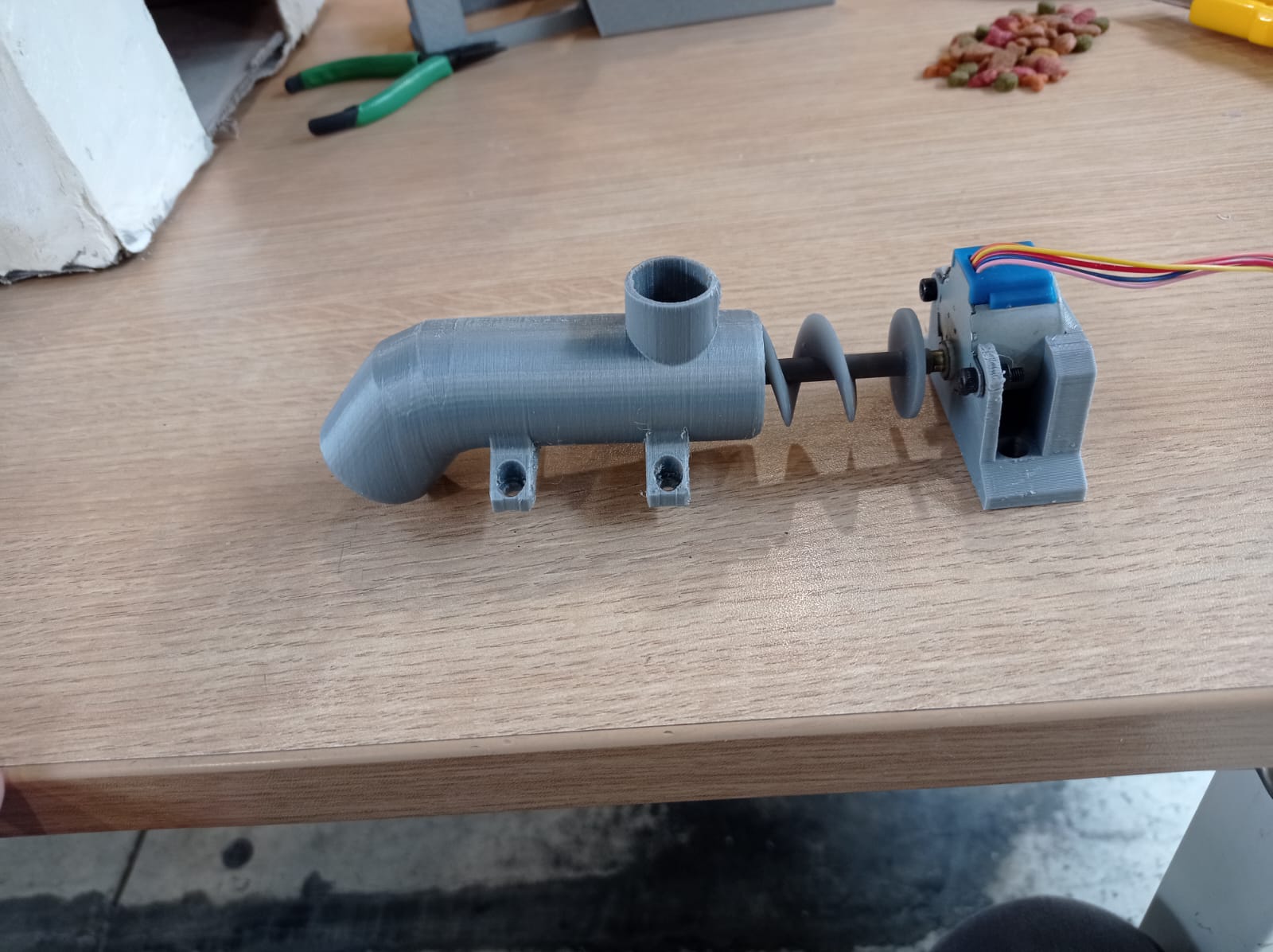
Figure N°37
We see that it moves in the proper way.
Video N°6
With this we can start the tests to pour the cookies on the plate.
Video N°7
2 PCB's were designed for this project, the first one has as its central part the XIAO ESP32 module with step response.
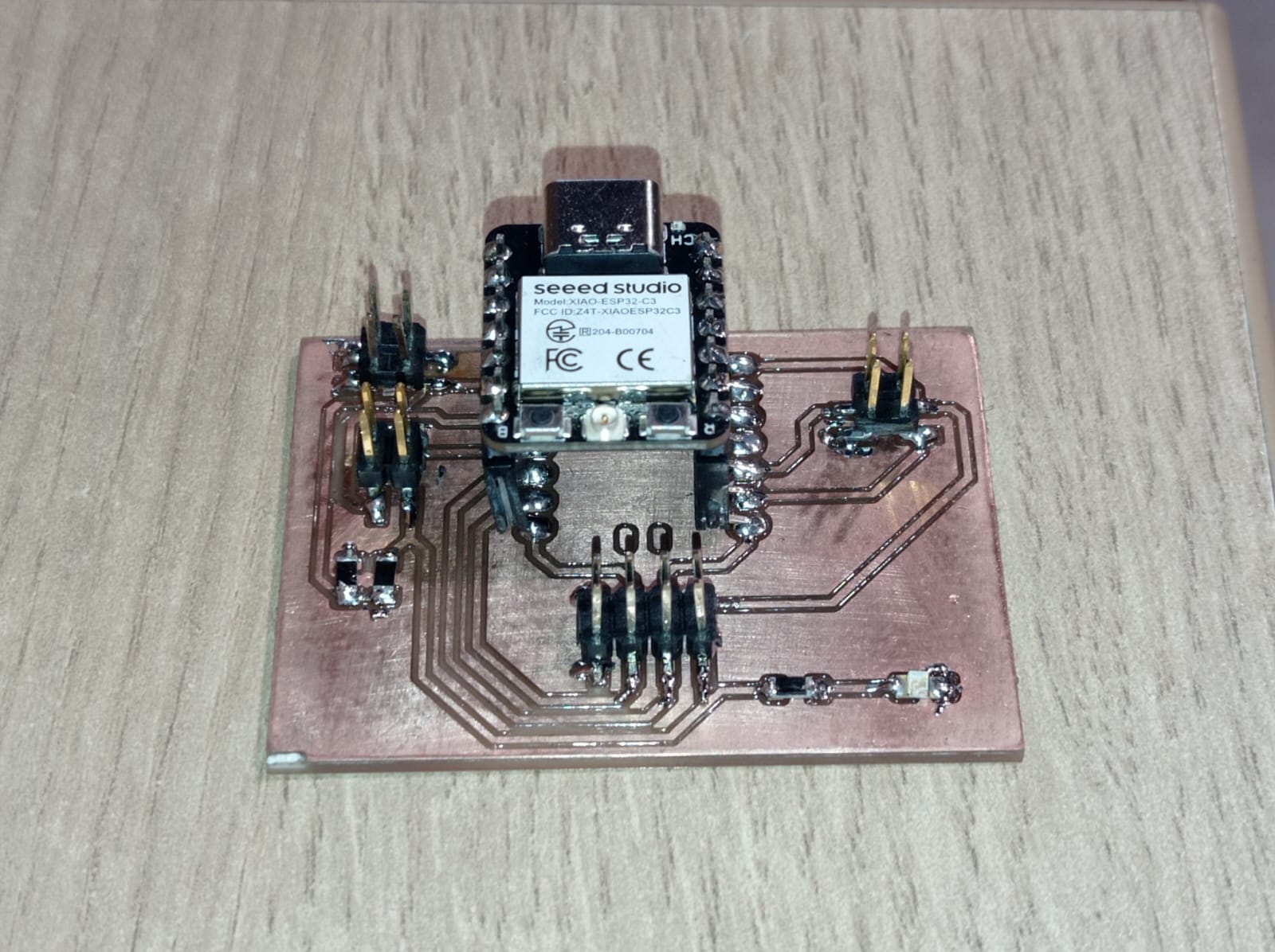
Figure N°38
The other is a driver for the stepper motor based on a UNL2003.
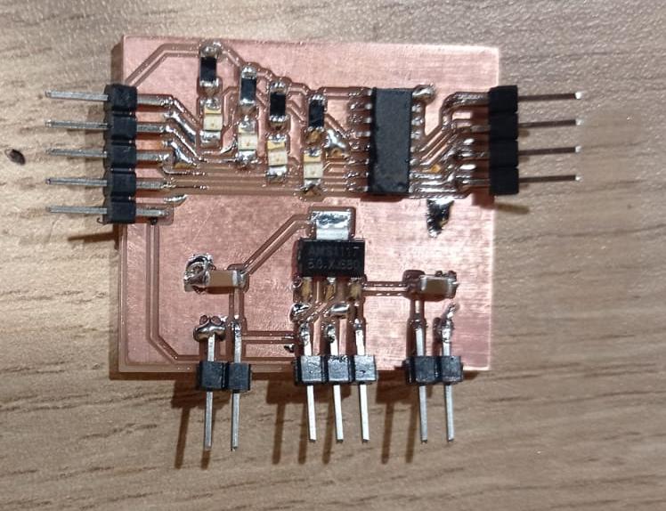
Figure N°39
After all the previous tests, the electrodes were designed circularly.
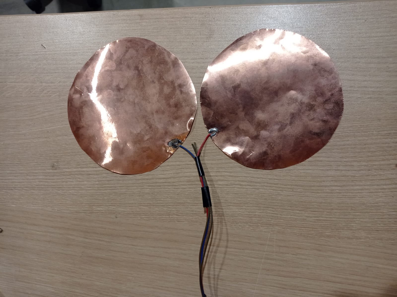
Figure N°40
These are placed like a sandwich and the plate goes on top.
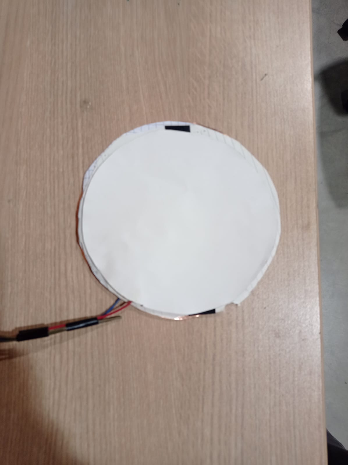
Figure N°41
We see that changes in the signal are detected at the time of adding the cookies.
Video N°8
And being a larger amount the signal is more noticeable.
Video N°9
Additionally we use the VL6180X sensor to measure the amount of cookies in the container.
Video N°10
Here we see all the parts integrated into the internal structure.
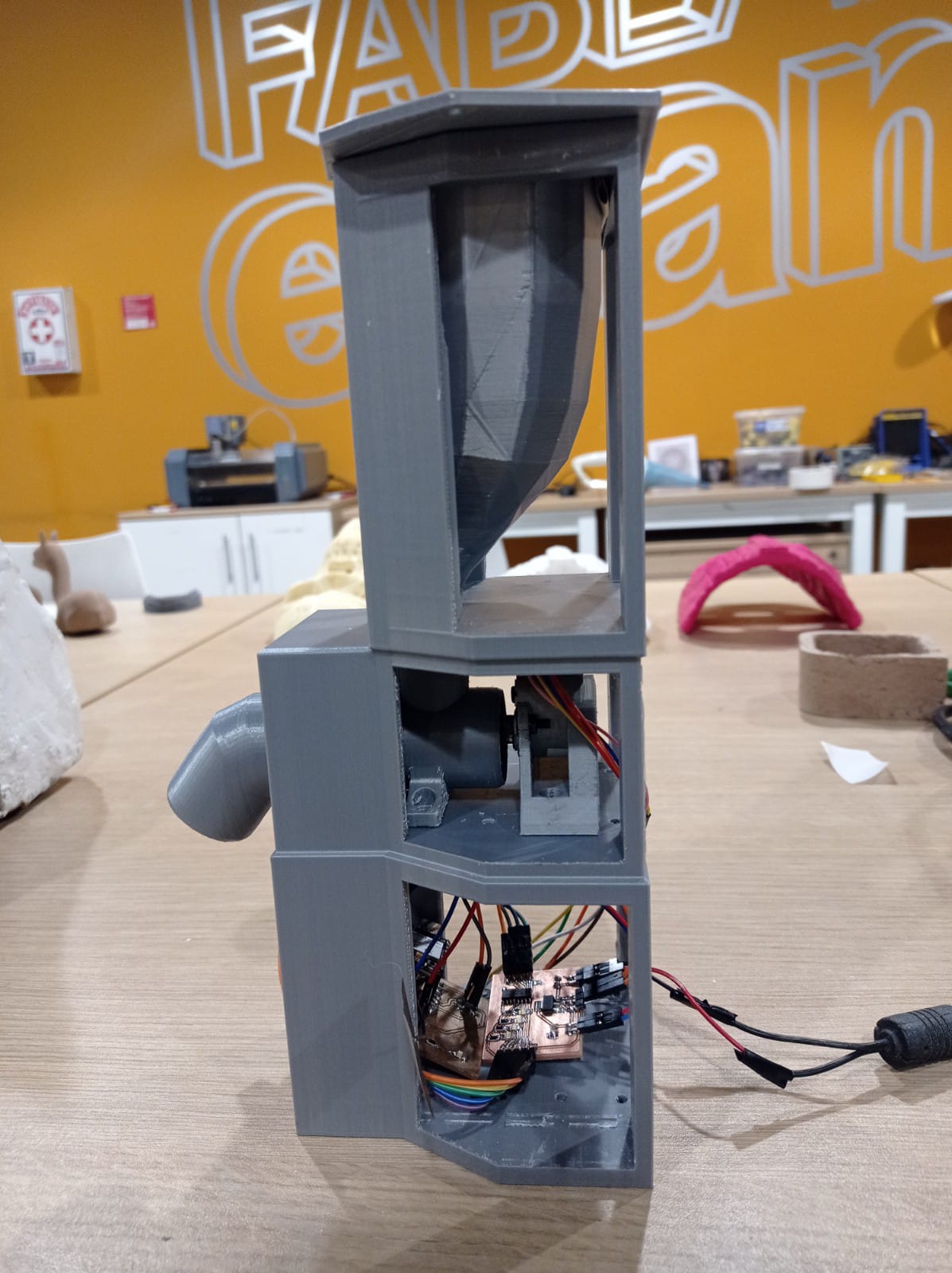
Figure N°42
We are going to join it with the external casing that we made with composites.
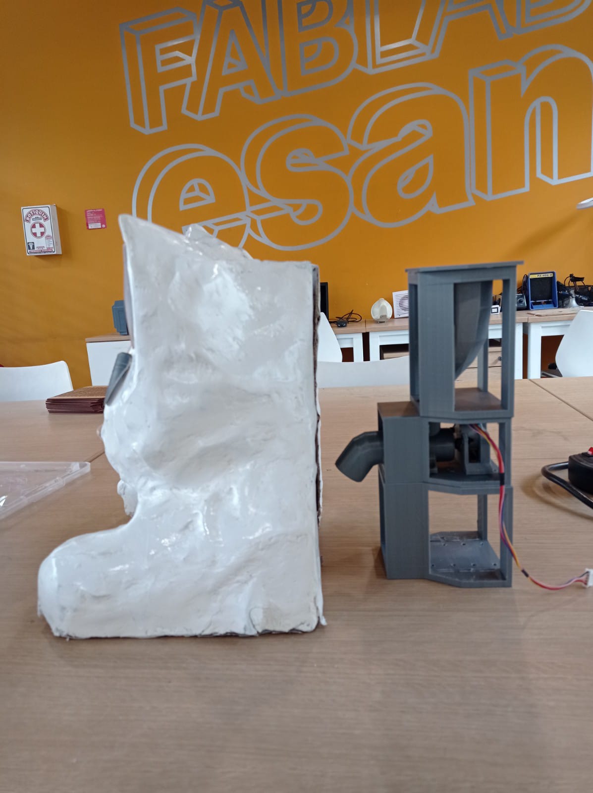
Figure N°43
All this section is placed in the back.
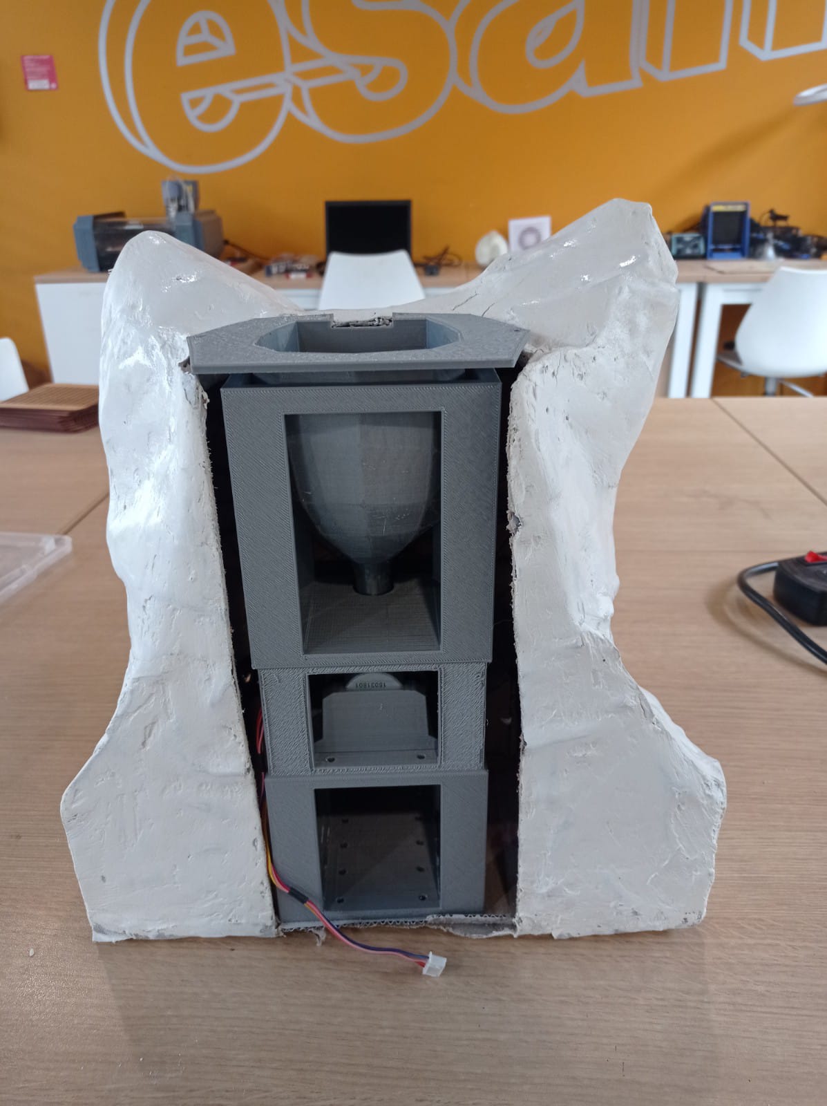
Figure N°44
Having all the parts integrated we redo the food displacement tests.
Video N°11
And finally we evaluate the change of the signal with the cookies leaving the device. The result is more than satisfactory.
Video N°12
| Component | Amount | Cost | Referral supplier |
|---|---|---|---|
| XIAO ESP32 | 1PCS | 9.9 USD | Link |
| Stepper motor 28byj-48 | 1PCS | 12.9 USD | Link |
| ULN2003 driver | 1PCS | 0.6 USD | Link |
| VL6180X | 1PCS | 4.5 USD | Link |
| PLA filament | 1PCS | 20 USD | Link |
| Cardboard | 1PCS | 5 USD | Link |
| Epoxy Resin | 1PCS | 16.9 USD | Link |
| Fabric | 1PCS | 2 USD | Link |
| Miscellaneous electronic components | 1PCS | 16.9 USD | Link |
A slide was designed to show all the work of this final project.
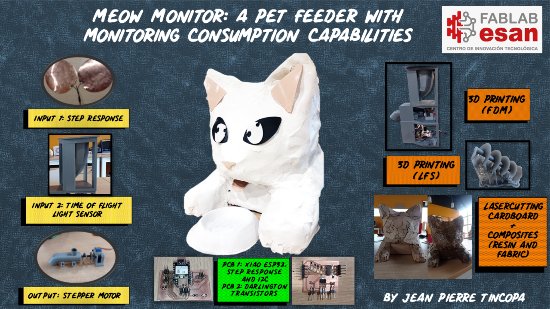
Figure N°45
And a video was made that summarizes each of the parts and demonstrations.
Video N°13
The files created or used for the final project can be downloaded here:
| Cat case (.STL) | Link |
| PCB XIAO-ESP32 (KiCAD) | Link |
| PCB Stepper Motor Driver (KiCAD) | Link |
| PCB ESP32-WROOM-32 (KiCAD) | Link |
| Cat Casing (.STL) | Link |
| Cat internal structure p1 (.STL) | Link |
| Cat internal structure p2 (.STL) | Link |
| Cat internal structure p3 (.STL) | Link |
| Cat internal structure p4 (.STL) | Link |
| Shift Worm (.STL) | Link |
| Script 01 - Step Response + Stepper Motor (.INO) | Link |
| Script 02 - Ligth Sensor (.INO) | Link |
The chosen license is Creative Commons Attribution-ShareAlike 4.0 International (CC BY-SA 4.0).
Under this license, you are free to:
The licensor cannot revoke these freedoms as long as you abide by the license terms.
Here are the specific terms: