
This week's assignment is about molding and casting, where we will use different materials to make replicas of parts based on a mold.
In this section we will do casting tests of several materials with different properties. Before doing so, it is important to take into account basic security aspects.
The first thing is to have gloves since coming into direct contact with some materials can cause skin irritation, in the same way a KN95 mask or similar to avoid inhaling any particles of any material that has dust.
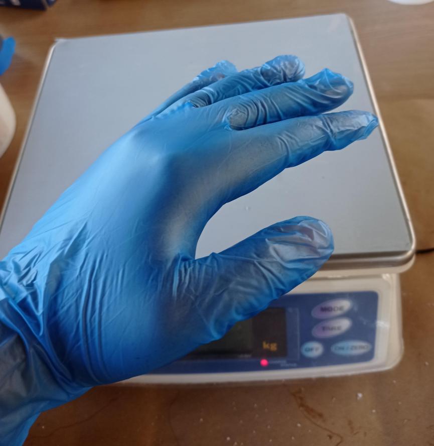
Figure N°1
It is also quite useful to have a paper towel to avoid wasting material when it is left dripping and cleaning the work area.

Figure N°2
And additionally, if we want to protect a work table, using some paper that covers the area will help us a lot since we can discard it later.
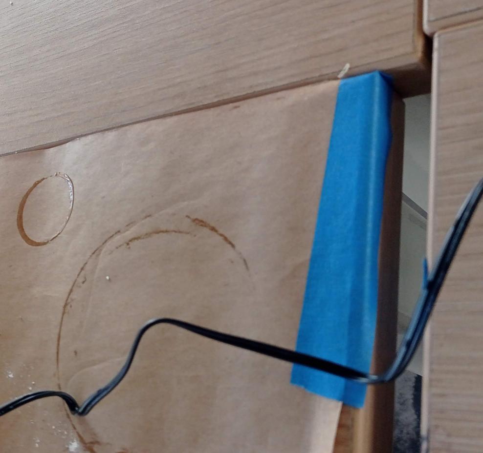
Figure N°3
The first material we are going to test is Hydro-Stone Super X, it is a fairly hard cement. You can see their data sheet here. In it we can see that this material can cause skin irritation and serious eye damage.
Therefore, the way to mix this material is as follows:
| Material | Hydro-Stone |
| Mixing Ratio | 1:5 |
| Example | 10gr(powder) : 50gr(water) |
Table N°1
We can see a photo of the product and the result after hardening.
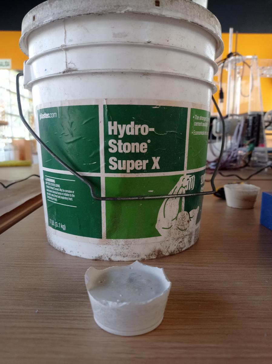
Figure N°4
Therefore, the way to mix this material is as follows:
| Material | DryStone |
| Mixing Ratio | 1:5 |
| Example | 10gr(powder) : 50gr(water) |
Table N°2
The second material that we will use will be Drystone which is similar to cement but with the ability to replicate finer models. You can see their data sheet here. In it we can see that when mixed with water, this material hardens and gets very hot, sometimes quickly, so no part of the body should be cast using this material.
We can see a photo of the product and the result after hardening.
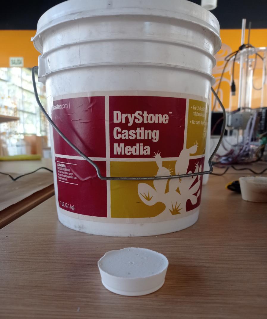
Figure N°5
As they are similar materials, we can compare them and indeed the Drystone was able to capture details of the plastic cup where they were mixed in a better way.

Figure N°6
Another relevant aspect is that Hydro-Stone is susceptible to having more bubbles as we can see in the image. In both cases, when there is a blow or crack, the material breaks, which can be a problem for some pieces.
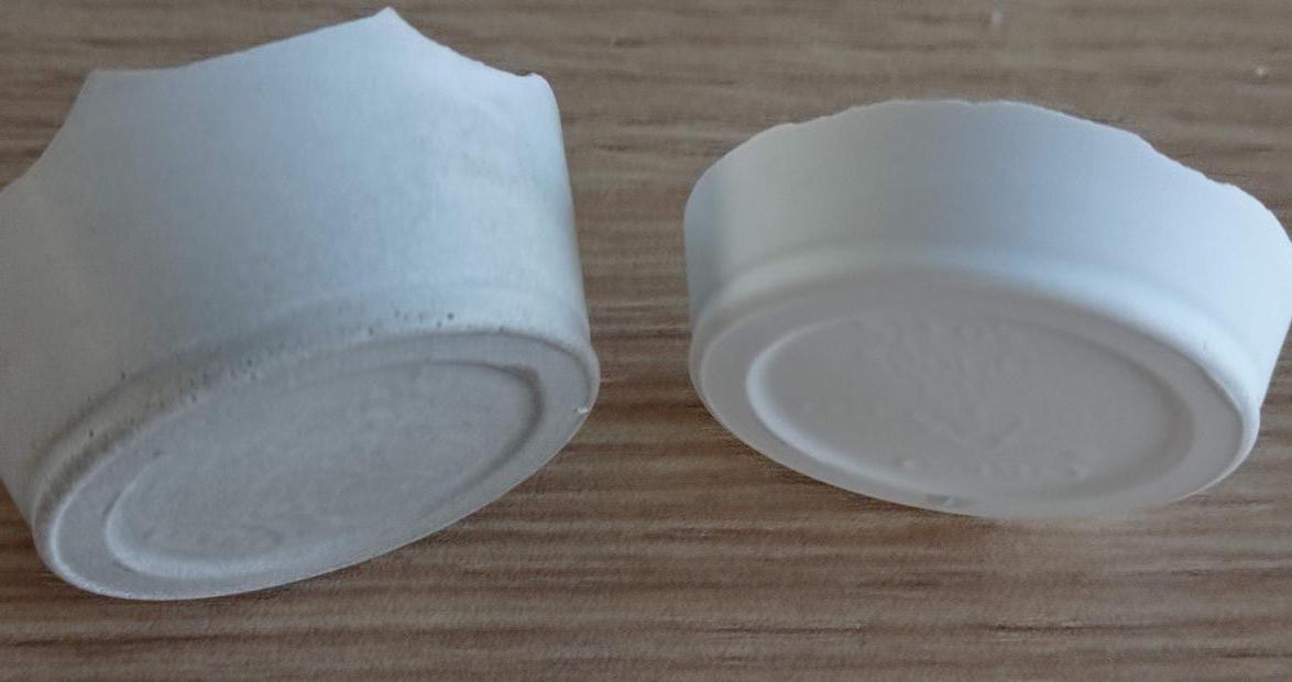
Figure N°7
The next material is polyurethane resin, this has the particularity of drying much faster and having a fairly good finish in details as well as being completely solid. You can see their data sheet here. In it we can see that smoking, eating and drinking must be prohibited in the application area.
Therefore, the way to mix this material is as follows:
| Material | Polyurethane |
| Mixing Ratio | 1:1 |
| Example | 20 ml(A) : 20 ml(B) |
Table N°3
We can see a photo of the product and the result after hardening.
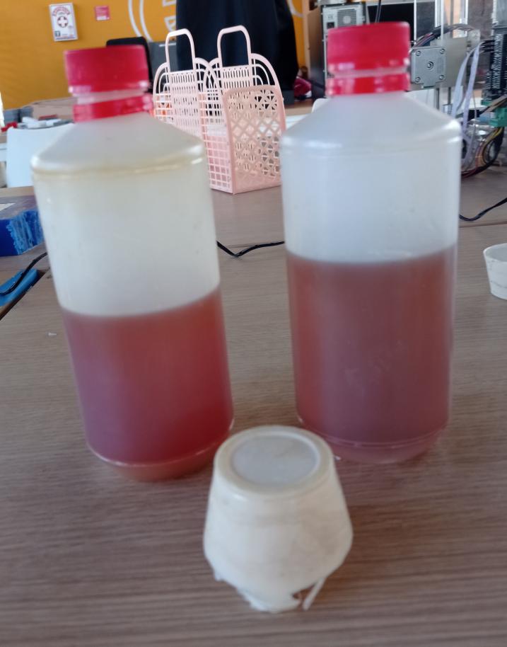
Figure N°8
Now we turn to the epoxy resin, the particularity of this material is that it is translucent and shiny but the drying time is much longer than that of the other materials, this being approximately 24 hours. You can see their data sheet here. In it we can see that this material is quite harmful to the skin and eyes while it is in its casting process.
Therefore, the way to mix this material is as follows:
| Material | Epoxy Resin |
| Mixing Ratio | 1:5 |
| Example | 10 ml(A) : 50 ml(B) |
Table N°4
We can see a photo of the product and the result after hardening.
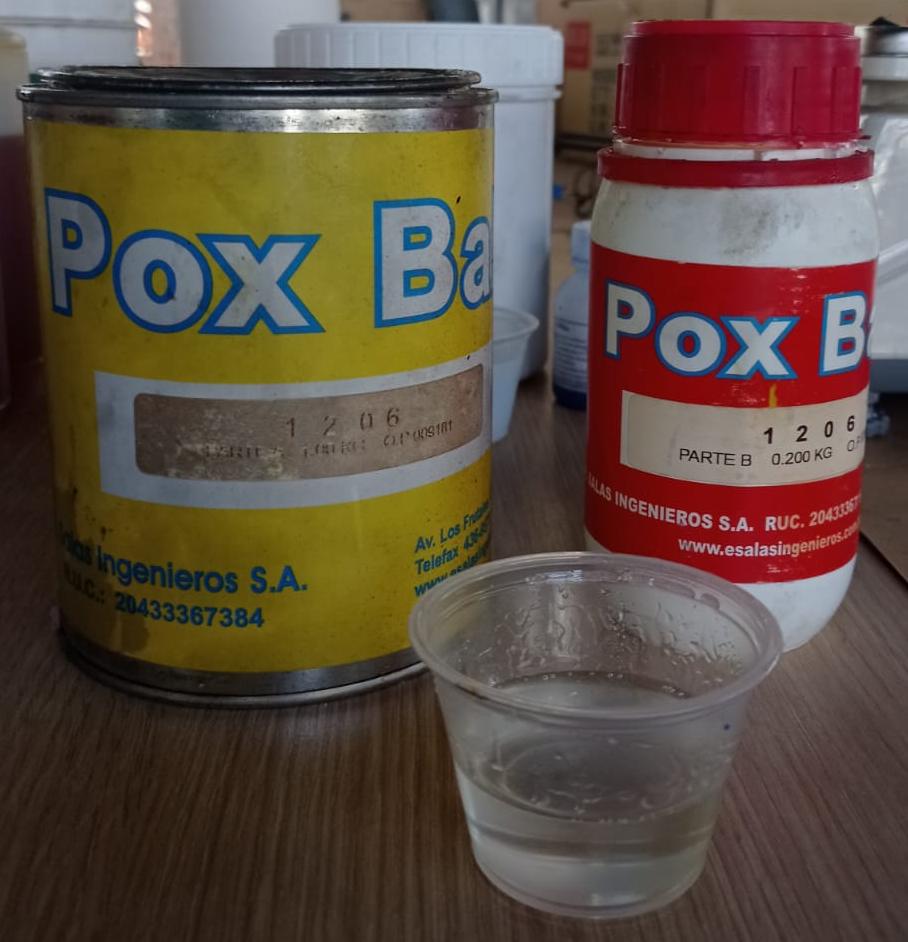
Figure N°9
Another important point about epoxy resin is that it should preferably be used with some method to eliminate the microbubbles that are generated when mixing, we see in the image that several of these microbubbles remain there.

Figure N°10
Finally we will do a test with silicone rubber F-10, this value indicates the level of hardness of the material, which is quite flexible and ideal for our molds. You can see their data sheet here. In it we can see that this material, like the others, is harmful to the eyes and skin while it is hardening.
Therefore, the way to mix this material is as follows:
| Material | Silicone |
| Mixing Ratio | 1:33 |
| Example | 2 ml(Catalyst) : 66 ml(Silicone) |
Table N°5
We can see a photo of the product and the result after hardening.
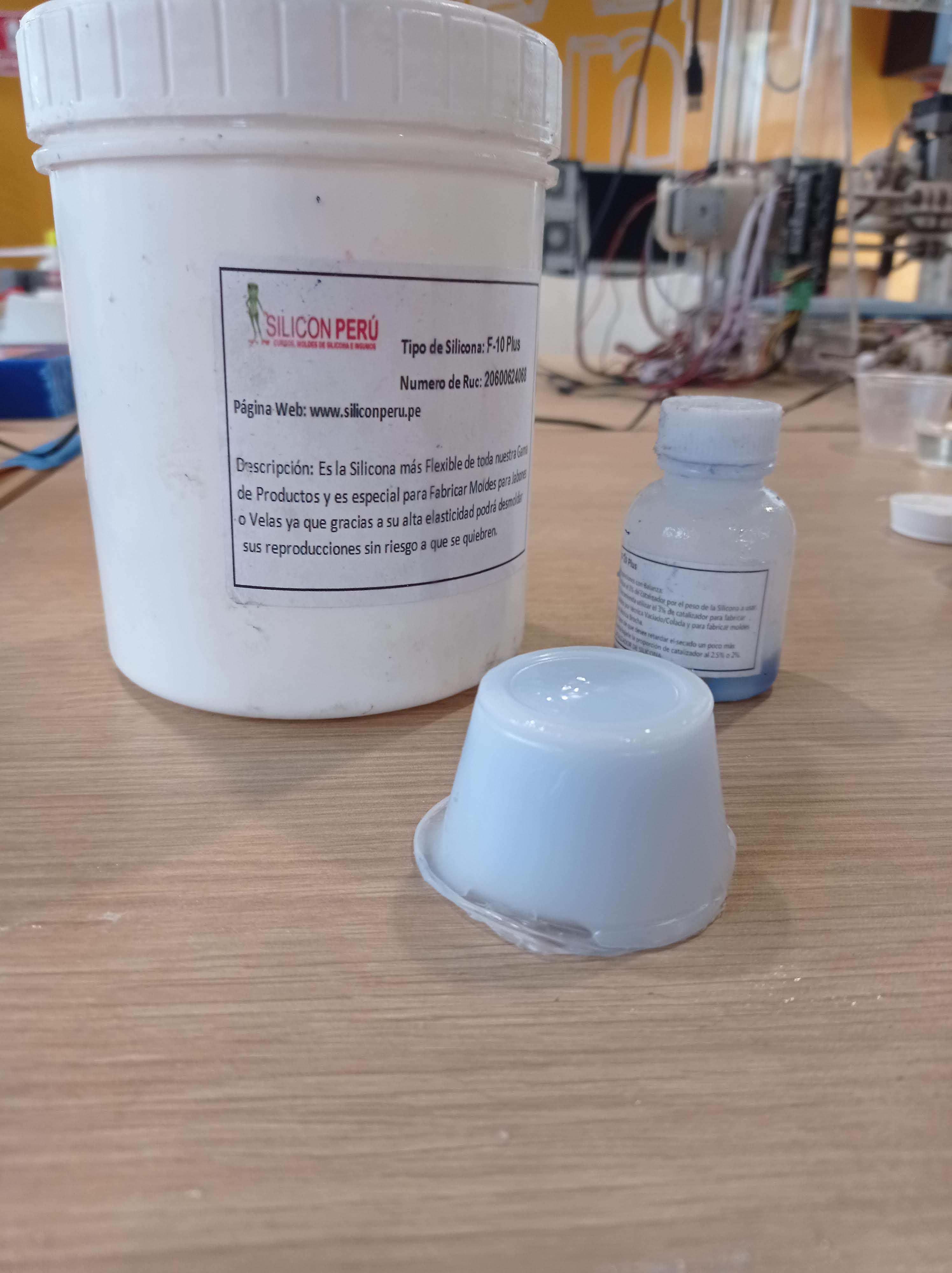
Figure N°11
Here a general photo of all the samples made with this material using the same plastic cups as a mold.

Figure N°12
In this section the objective is to manufacture the mold through rough cut and finish milling. For this reason, a lego mini figure has been selected that has rounded parts on the face and we will see how good a finish it gives in that section.
For this we have taken as a basis this design of free access from Thinguiverse.
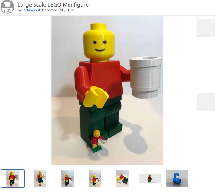
Figure N°13
The parts of the head, torso and hips were joined in a single piece so that this is the one that is going to be replicated, in addition, a modification was made in the fitting of the arms so that it was not hollow and could be done through milling.

Figure N°14
This model was mirrored to create an A and B mold.
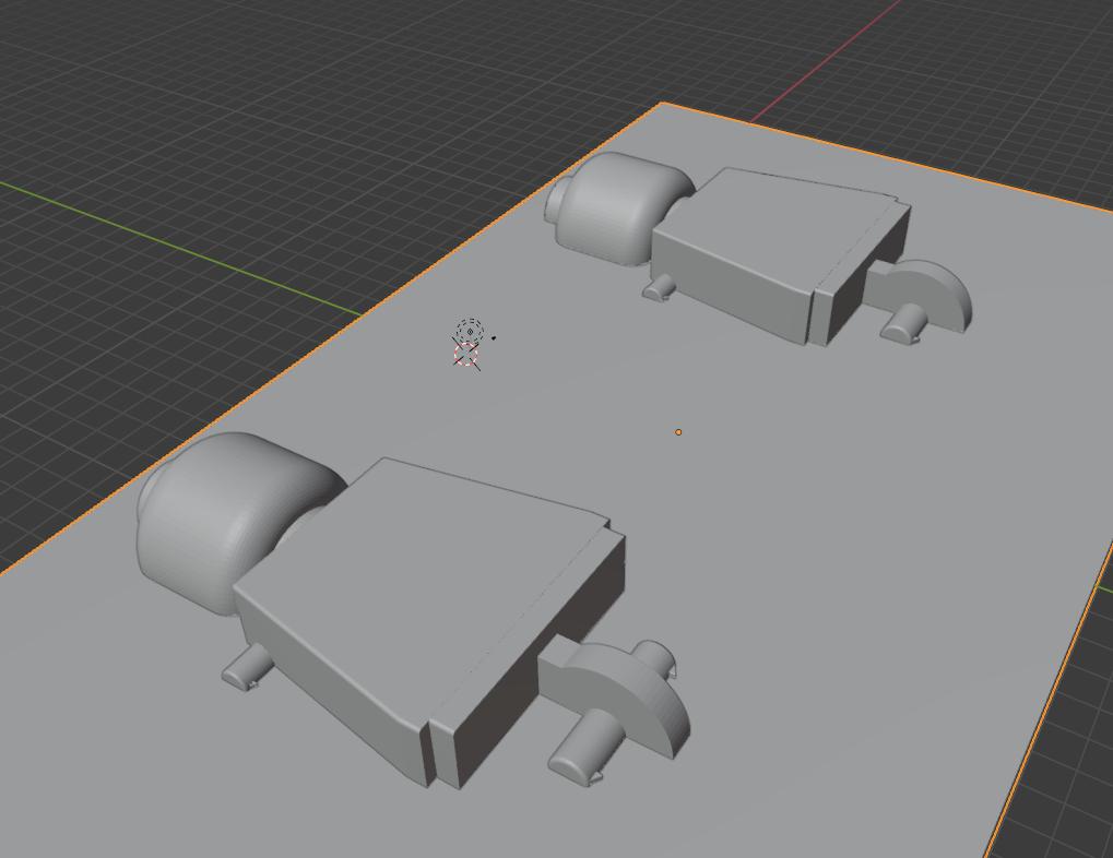
Figure N°15
Then lace areas were added so that when they are put together they have union points.
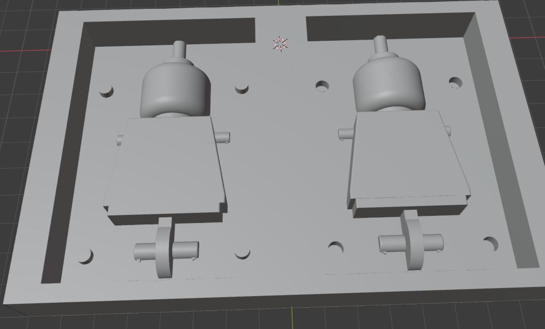
Figure N°16
To do the milling we use the fab module having as input a mesh (.stl) and output process a Roland MDX-20 mill (.rml).

Figure N°17
The parameters for this task would be the following:
| Wear type | Rough |
| Milling cutter diameter | 1/8'' |
| Type of milling | Square |
| Overlap | 1.25 |
| Speed | 20 mm/s |
Table N°6
Here we select the rough cut milling mode where we will use a flat cut bit. We enter the design in .stl format, create a route and generate the .rml file where it indicates the duration of the process.
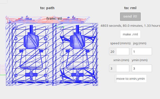
Figure N°18
In real time, the program shows us the routes and the percentage of progress of the process.
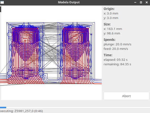
Figure N°19
We can see the result of this first stage with the rough cuts.
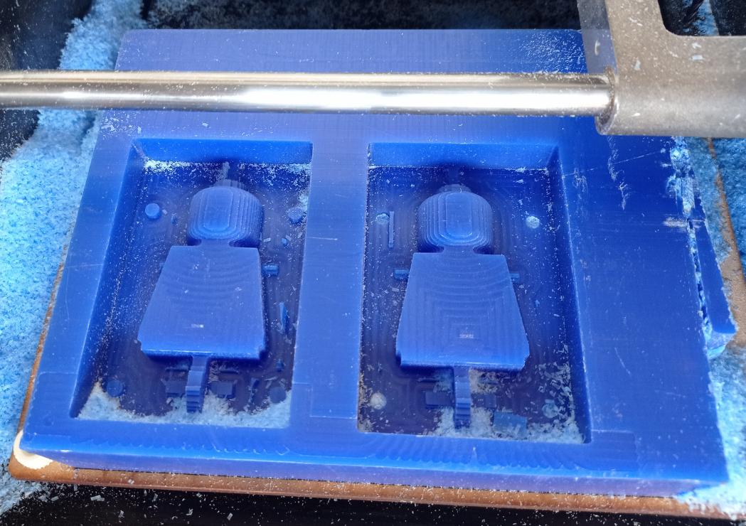
Figure N°20
When this task is finished, we repeat the process but to finish it, it is done with a rounded drill bit, in the same way we can see in real time how the process progresses.
The parameters for this task would be the following:
| Wear type | Finish |
| Milling cutter diameter | 1/8'' |
| Type of milling | Rounded |
| Overlap | 0.75 |
| Speed | 20 mm/s |
Table N°7
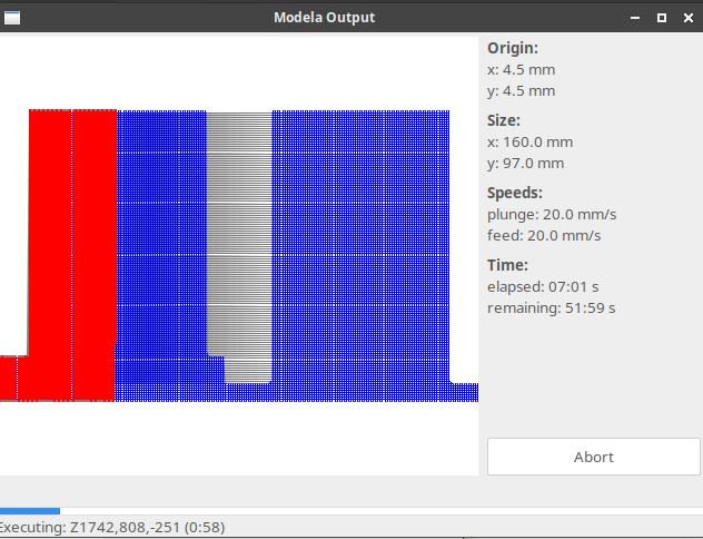
Figure N°21
Now you can see the rounded areas of the head and the result is optimal.
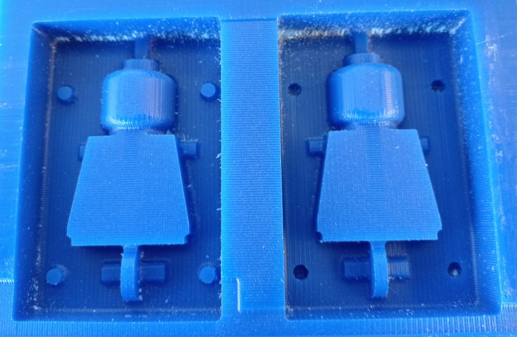
Figure N°22
This mold was built with a mix ratio according to table N°5.
Now we pour out the F-10 silicone to make a mold for each side A and B. We wait approximately 30 minutes.
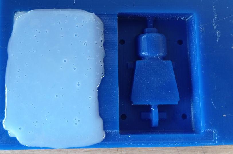
Figure N°23
We see the mold created with all the details of the design.
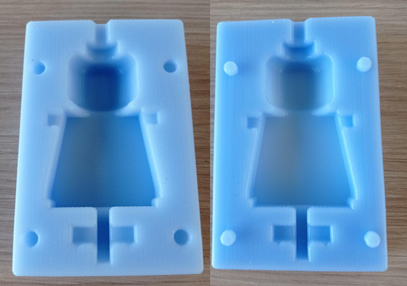
Figure N°24
Now to make the casting we will use an adhesive tape around the molds so that they stay in place.
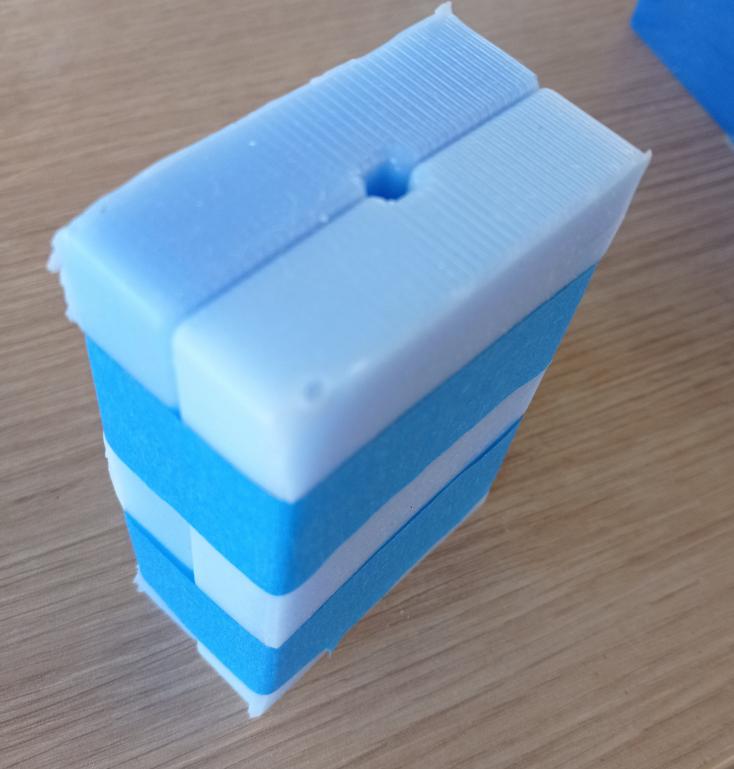
Figure N°25
In the materials tests we saw that one of the materials that best suited our objective and that is polyurethane, which we entered the mold with great difficulty due to the size of the hole.
This piece was built with a mix ratio according to table N°3.
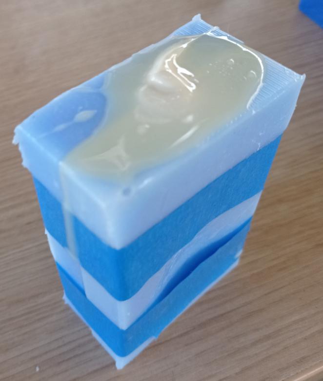
Figure N°26
Minutes later we observed that much of this mixture was left out and only a piece entered the mold and solidified.
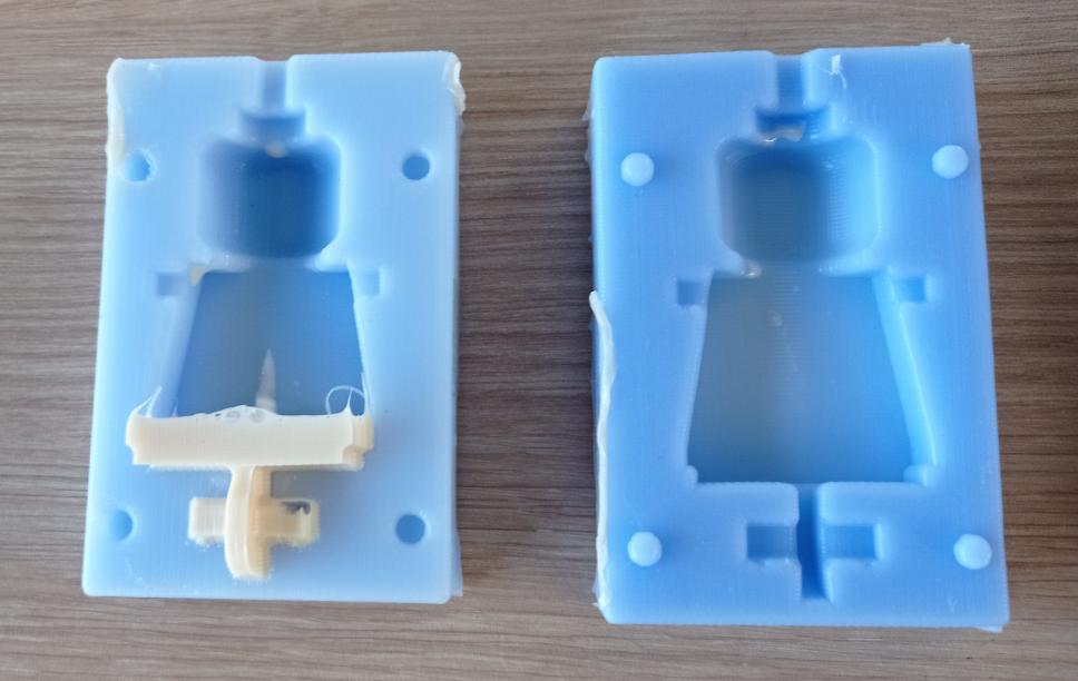
Figure N°27
Realizing that the entry of the sample must be freer, we manually cut the entry from the head with a blade.
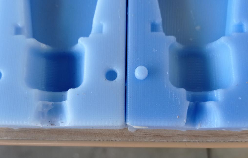
Figure N°28
With a larger cavity we will repeat the experiment.
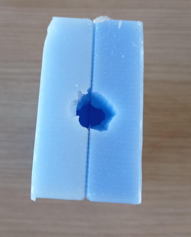
Figure N°29
We see the result where now if the entire sample entered the mold.

Figure N°30
Although the complete figure was formed between the space between the molds, the mixture was scattered, so that amount of residue comes out on the sides.
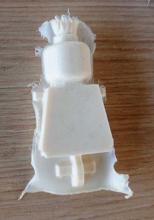
Figure N°31
To improve the pressure between the molds and reduce the mixture coming out, a couple of boxes were used that were handy with the tape.

Figure N°32
We see that this manages to reduce the excess a lot but even so there is a little that continues to come out.

Figure N°33
In addition to this, the presence of bubbles in the piece is noted.
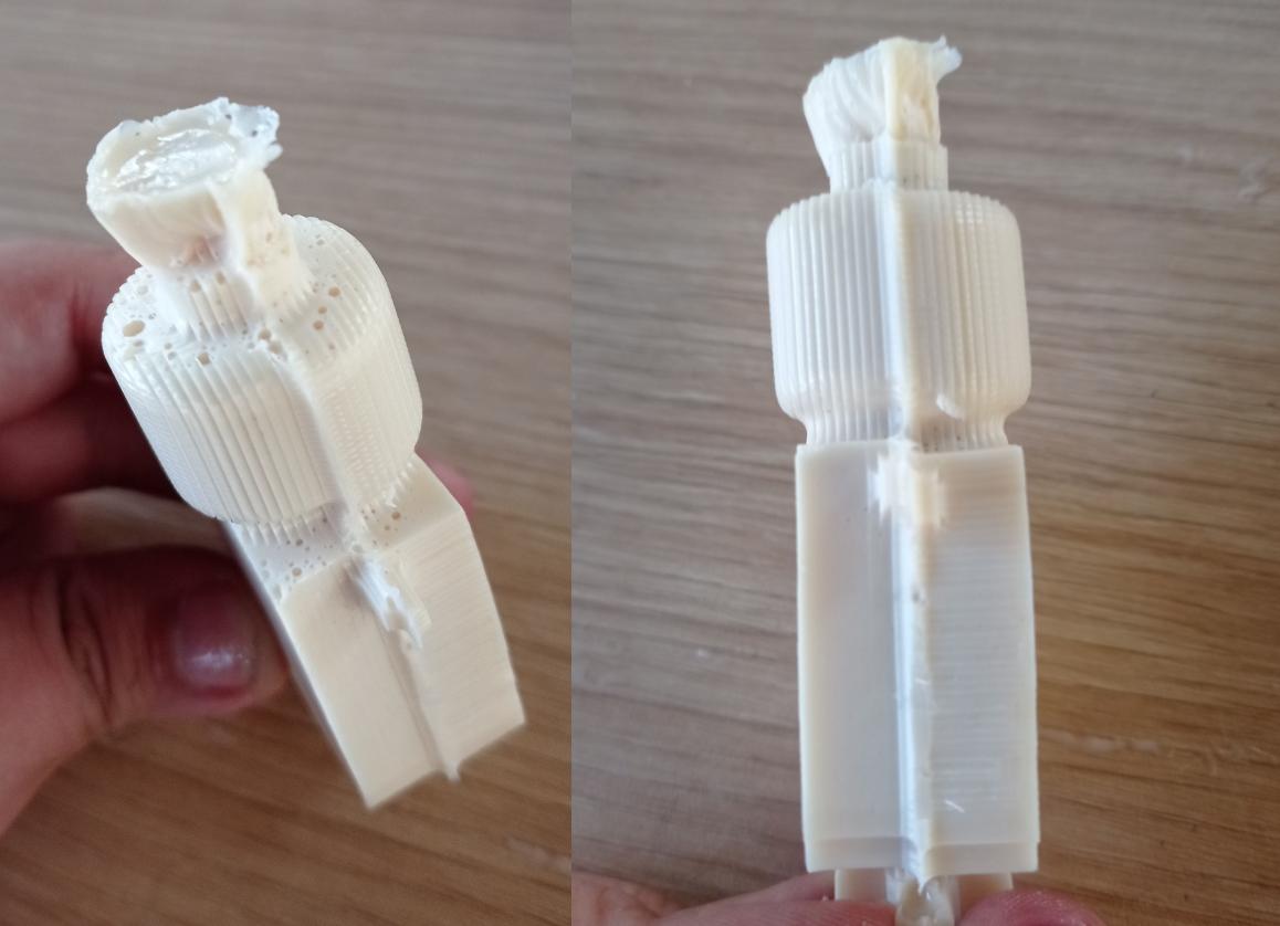
Figure N°34
We repeat this process in epoxy resin and wait 24 hours.
This piece was built with a mix ratio according to table N°4.

Figure N°35
In the same way we still have the problem of the space between molds.
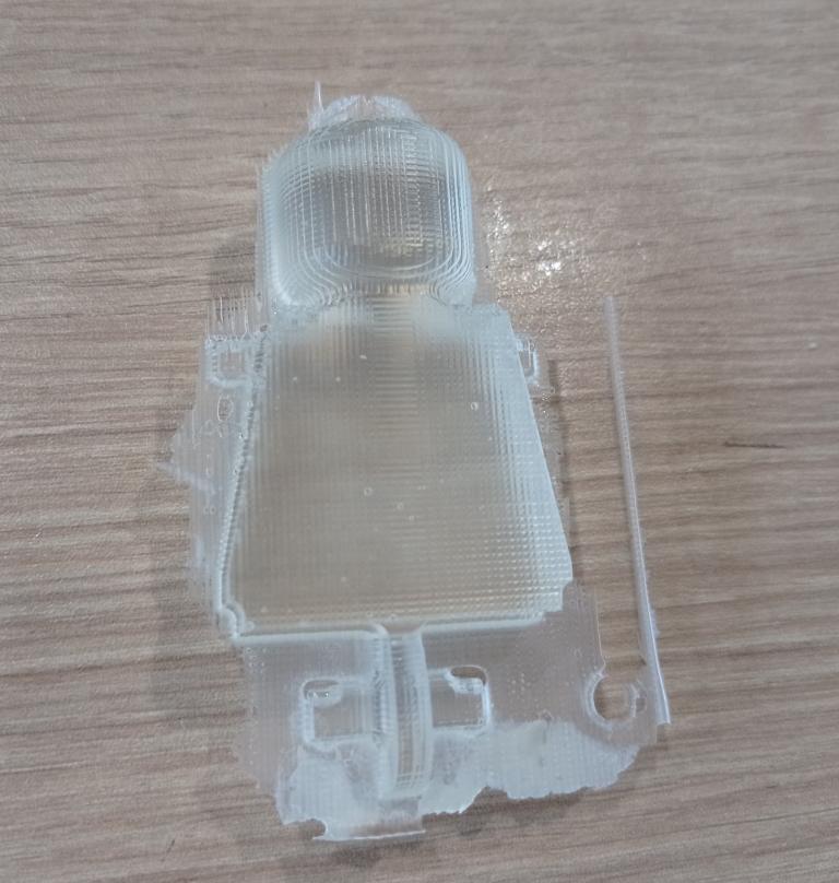
Figure N°36
In addition to this, the boxes generated uneven pressure causing one of the molds to move to one side, which is why the piece came out asymmetrical.
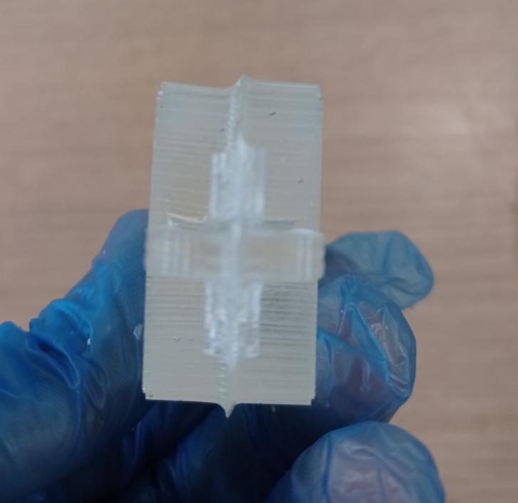
Figure N°37
New molds were created by placing plasticine in the head area to enlarge the diameter.
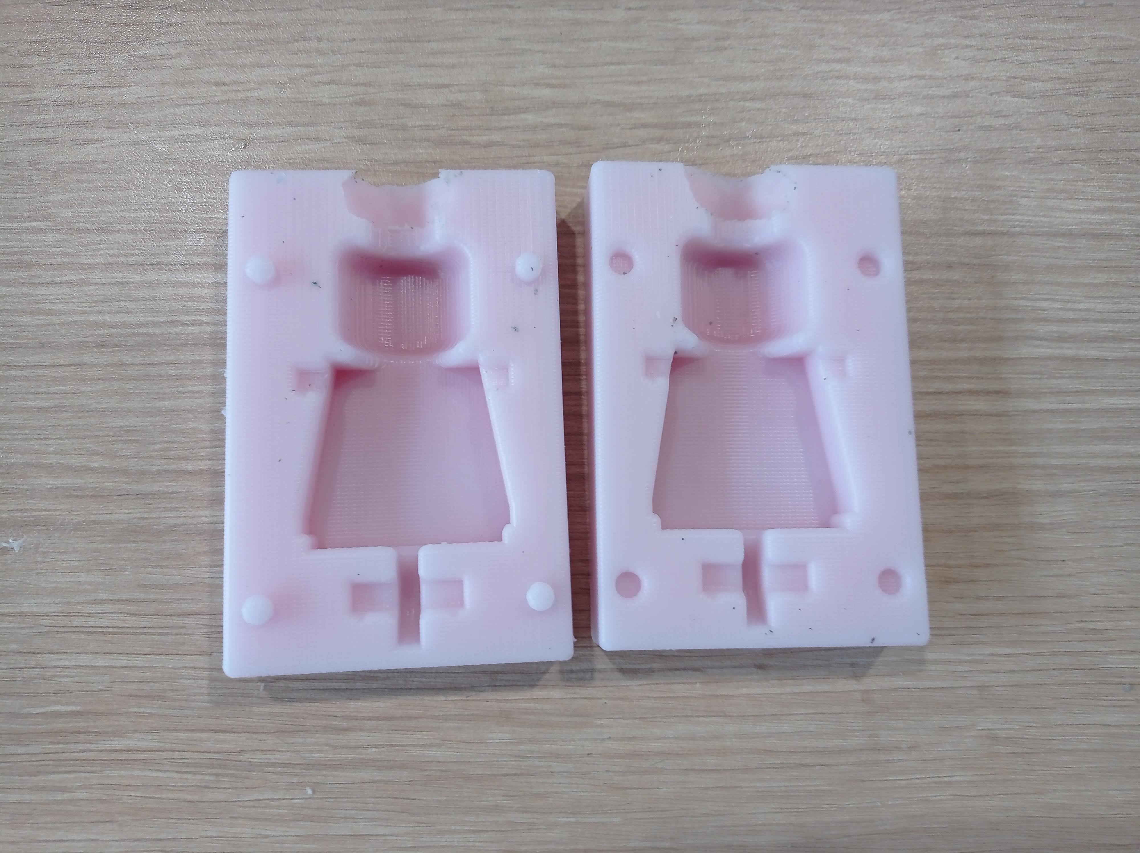
Figure N°38
This time instead of using boxes with irregular shapes we will have 2 pieces of flat MDF with a press, with this we will make the pressure uniform throughout the molds.
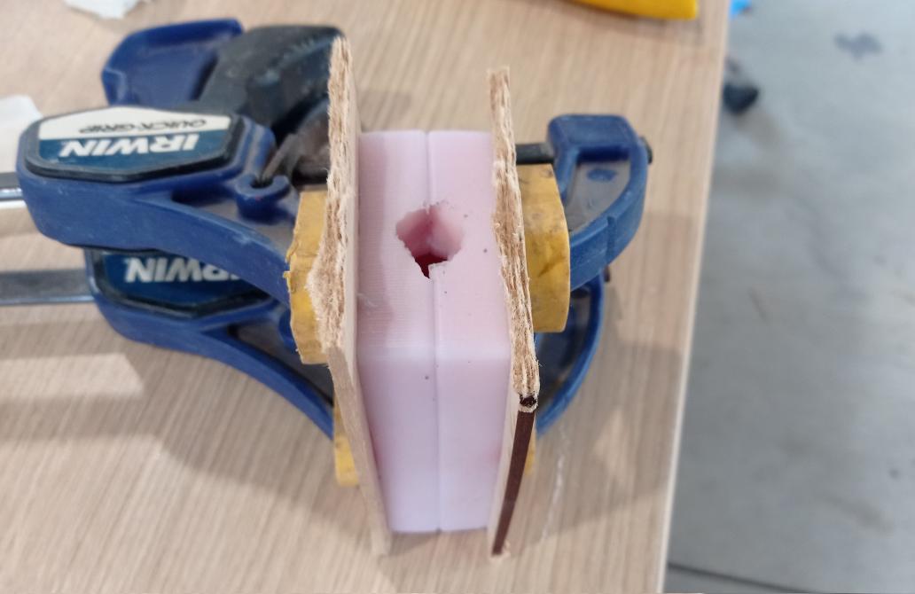
Figure N°39
We can see that the result is much better, but bubbles remained in the leg and arm lace areas that caused the piece to come out incomplete in one sector.

Figure N°40
By placing some 3D printed legs, we appreciate that they fit easily with the polyurethane sample.
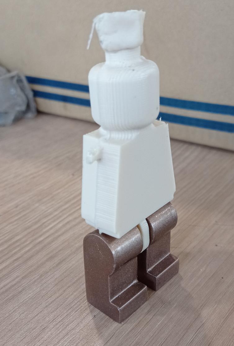
Figure N°41
In the same way with epoxy resin, the lace with legs is quite good.
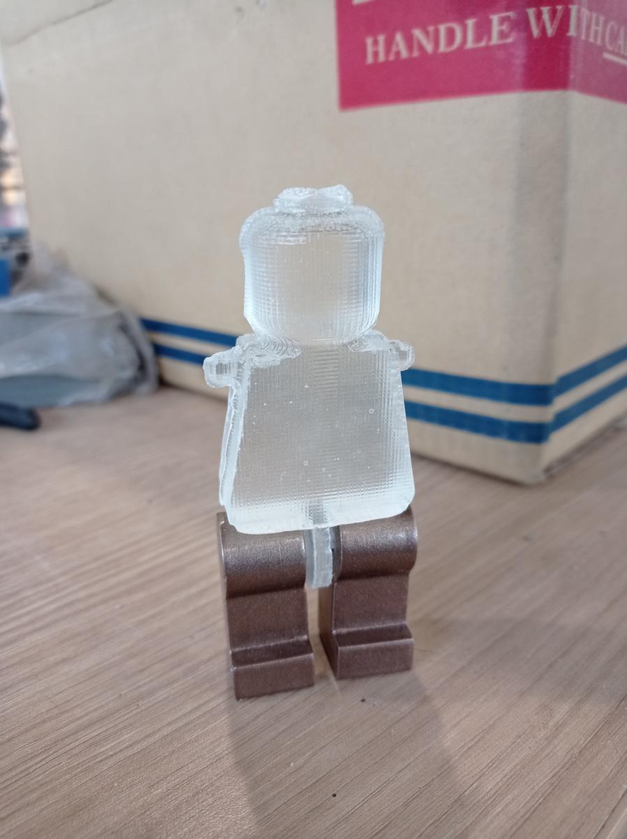
Figure N°42
Now we will try to replicate the legs of the figure, for this we will create some molds that will not be equal to each other since we have a different internal diameter so that they fit with the body and can rotate
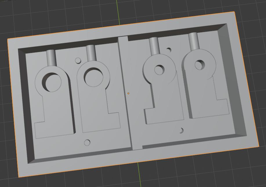
Figure N°43
We repeat the entire process using an .stl file as input and an .rml as output

Figure N°44
We see the result of the first rough cutting process.

Figure N°45
Then we go to the finishing cut where the rounded parts are more appreciated.

Figure N°46
We do a silicone casting in the same way, a bubble stayed inside one of the legs.
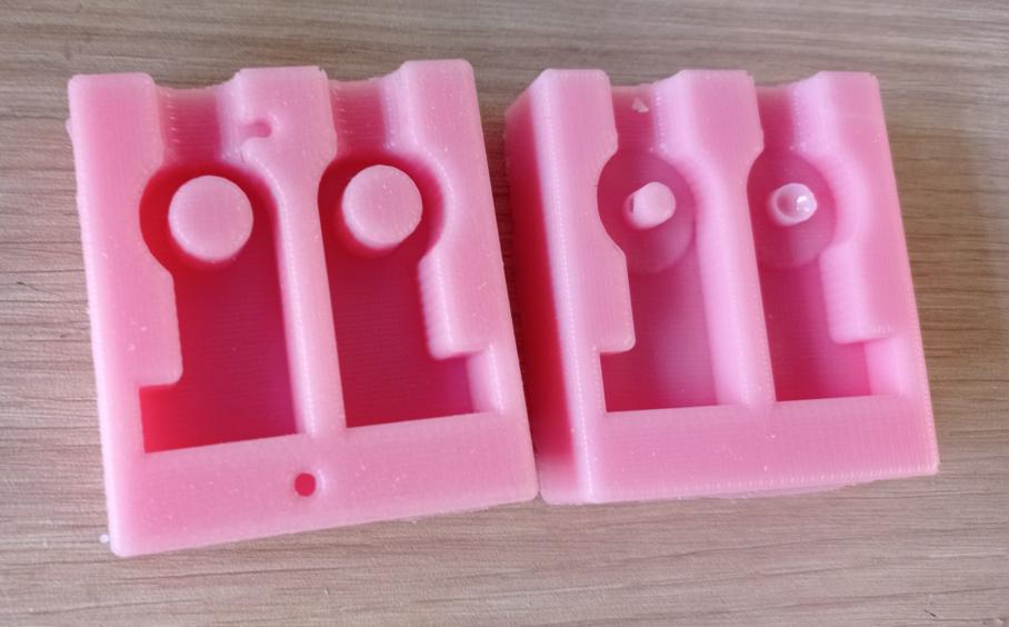
Figure N°47
We will use the MDF pieces and the press to avoid leakage of material.

Figure N°48
And this is the result together with the legs, together with some 3D printed arms we have the complete figure!

Figure N°49
The files created or used this week can be downloaded here:
| Body mold | Link |
| Leg Mold | Link |