
This week's assignment is to use networking and integrated communications to communicate different devices.
In this section we will make two devices communicate with each other using some communication protocol.
To begin we are going to design printed circuit boards based on microcontrollers that have the ability to communicate wirelessly.
We will use an ESP32-WROOM-32, with this chip we can communicate both via WiFi or via Bluetooth.
The first design is made so that various protocols can be used externally, such as I2C, UART and several GPIOs, in addition to the fact that the programming of this chip will be through an FTDI.

Figure N°1
We have a preview of the design.
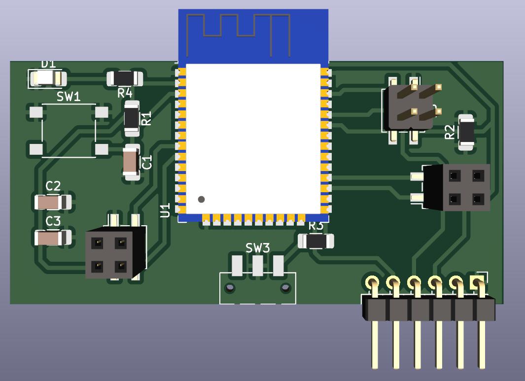
Figure N°1
And so the implementation of it was left, an important detail is that one of the tracks was so close to the edge that when it was cut by the milling machine it disappeared, so it was decided to use a wired bridge.
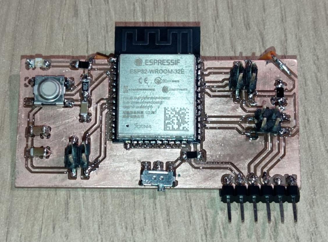
Figure N°1
In the second design we will also use a module based on ESP32 but with a complete module which is the XIAO-ESP32.
In the same way, the board was designed with so many inputs so that it can use I2, UART, etc.
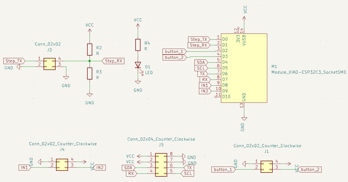
Figure N°1
We have a preview of the design.
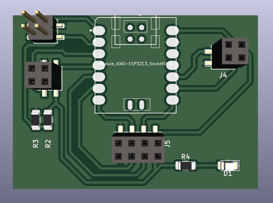
Figure N°1
And so the implementation of the same was left, where the module was not soldered directly but used sprats so that it can be removed from the PCB.
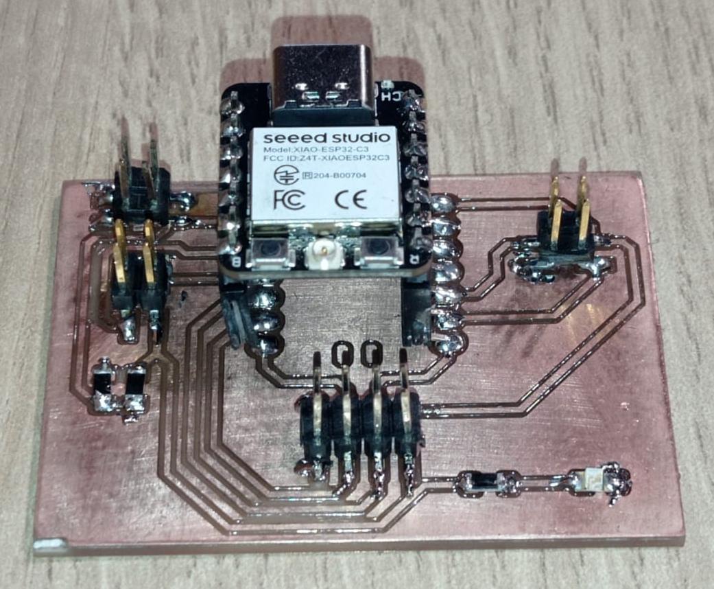
Figure N°1
In this first example we connect an arduino Mega and one of the modules designed to carry out serial communication.
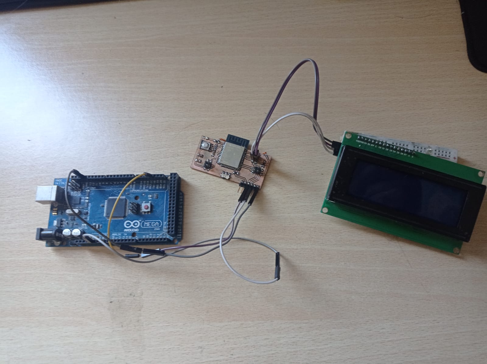
Figure N°1
Regarding Script No. 1, we take advantage of the fact that the Arduino Mega has several serial communication pins, since we will use a data entry via the serial monitor.
                      char message[20]="HOLA";
                      int indice;

                      void setup() {
                       Serial.begin(9600);
                       Serial1.begin(9600);
                      }
                      void loop() {
                        if (Serial.available()>0)
                        {
                        indice = Serial.readBytesUntil('\n', message, 19);
                        message[indice] = '\0';
                          Serial1.println(message);
                          delay(1000);
                        }
                      }
In Script N°2 we will use a 20*04 LCD screen connected to the ESP32 through the UART protocol.
                      #include
                        #include
                        LiquidCrystal_I2C lcd(0x27,20,4);
                        char message[20];
                        int indice;

                        void setup() {
                         Serial.begin(9600);
                         lcd.init();
                         lcd.backlight();
                        }

                        void loop() {

                         if (Serial.available()>0)
                          {
                          indice = Serial.readBytesUntil('\n', message, 19);
                          message[indice] = '\0';
                          Serial.println(message);
                          lcd.setCursor(0,0);
                          lcd.print("Received message:");
                          lcd.setCursor(0,2);
                          lcd.print(message);
                          delay(100);
                          }
                        }
We can see a demonstration where we enter values via the serial monitor and these are written to the LCD screen.
Video N°1
From here the objective is to make wireless communications between the two devices designed here.
For wireless communication we use a simple communication protocol called UDP which stands for User Datagram Protocol.
The base scripts used here are from this source.

Figure N°13
Here it is necessary first to make both devices connect to the same network, in my case my home network for some reason did not allow the devices to connect, so I used the cell phone network.
Another important point is that UDP sends data to the other device using its IP address, so we must first know what its address is within the network, when the connection is successful, a data packet is sent, in this example the number of milliseconds that have elapsed.
                      #include
                        #include
                        WiFiUDP udp;
                        char packetBuffer[255];
                        unsigned int localPort = 9999;
                        const char* ssid = "wifi_fab";
                        const char* password = "12345678";


                        void setup() {
                          Serial.begin(115200);
                          WiFi.begin(ssid, password);
                          while (WiFi.status() != WL_CONNECTED){
                            delay(500); Serial.print(F("."));
                          }
                          udp.begin(localPort);
                          Serial.printf("UDP Client : %s:%i \n", WiFi.localIP().toString().c_str(), localPort);
                        }

                        void loop() {
                          int packetSize = udp.parsePacket();
                          Serial.print(" Received packet from : "); Serial.println(udp.remoteIP());
                          Serial.print(" Size : "); Serial.println(packetSize);
                          if (packetSize) {
                            int len = udp.read(packetBuffer, 255);
                            if (len > 0) packetBuffer[len - 1] = 0;
                            Serial.printf("Data : %s\n", packetBuffer);
                          }
                          Serial.println("\n");
                          delay(500);
                          Serial.print("[Client Connected] ");
                          Serial.println(WiFi.localIP());
                          udp.beginPacket("192.168.217.229", localPort); //IP a donde se envia
                          udp.printf("Send millis: ");
                          char buf[20];
                          unsigned long testID = millis();
                          sprintf(buf, "%lu", testID);
                          udp.printf(buf);
                          udp.printf("\r\n");
                          udp.endPacket();
                        }
In the server part, the network configuration is the same, when the data transmission has been successful a confirmation message is sent.
                      #include
                        #include
                        WiFiUDP udp;
                        char packetBuffer[255];
                        unsigned int localPort = 9999;

                        const char* ssid = "wifi_fab";
                        const char* password = "12345678";


                        void setup() {
                          Serial.begin(115200);
                          WiFi.begin(ssid, password);
                          while (WiFi.status() != WL_CONNECTED){
                            delay(500); Serial.print(F("."));
                          }
                          udp.begin(localPort);
                          Serial.printf("UDP server : %s:%i \n", WiFi.localIP().toString().c_str(), localPort);
                        }

                        void loop() {
                          int packetSize = udp.parsePacket();
                          Serial.print(" Received packet from : "); Serial.println(udp.remoteIP());
                          Serial.print(" Size : "); Serial.println(packetSize);
                          if (packetSize) {
                            int len = udp.read(packetBuffer, 255);
                            if (len > 0) packetBuffer[len - 1] = 0;
                            Serial.printf("Data : %s\n", packetBuffer);
                            udp.beginPacket(udp.remoteIP(), udp.remotePort());
                            udp.printf("UDP packet was received OK\r\n");
                            udp.endPacket();
                          }
                          Serial.println("\n");
                          delay(500);
                          Serial.print("[Server Connected] ");
                          Serial.println (WiFi.localIP());
                        }
We see that every 500 milliseconds a data is sent and there is a confirmation of both the message and the size of the message.

Figure N°13
In this example we will modify the previously used code so that we can control a servo motor through this wireless communication.

Figure N°13
The main change here is that the use of the servo motor, as we are using an ARM architecture microcontroller such as the ESP32, the timers must be configured differently to be used in servo motors. The name of the library used is ESP32Servo.h, also within the setup function we establish the frequency of the signal, which in this case is 50Hz because we are using an SG90 servomotor.
We create a conditional where we evaluate the size of the received packet, if it meets the condition the position of the servomotor will change.
                      #include
                        Servo myservo;
                        #include
                        #include
                        WiFiUDP udp;
                        char packetBuffer[255];
                        unsigned int localPort = 9999;

                        const char* ssid = "wifi_fab";
                        const char* password = "12345678";

                        int servoPin = 4;

                        void setup() {
                         ESP32PWM::allocateTimer(0);
                          ESP32PWM::allocateTimer(1);
                          ESP32PWM::allocateTimer(2);
                          ESP32PWM::allocateTimer(3);
                          myservo.setPeriodHertz(50);// Standard 50hz servo
                          myservo.attach(servoPin, 500, 2400);


                          Serial.begin(115200);
                          WiFi.begin(ssid, password);
                          while (WiFi.status() != WL_CONNECTED){
                            delay(500); Serial.print(F("."));
                          }
                          udp.begin(localPort);
                          Serial.printf("UDP server : %s:%i \n", WiFi.localIP().toString().c_str(), localPort);
                        }

                        void loop() {
                          int packetSize = udp.parsePacket();
                          Serial.print(" Received packet from : "); Serial.println(udp.remoteIP());
                          Serial.print(" Size : "); Serial.println(packetSize);

                            if(packetSize==10){
                            myservo.write(90);
                            delay(100);
                            }
                            else{
                            myservo.write(0);
                            delay(100);  }

                          if (packetSize) {
                            int len = udp.read(packetBuffer, 255);
                            if (len > 0) packetBuffer[len - 1] = 0;
                            Serial.printf("Data : %s\n", packetBuffer);

                            udp.beginPacket(udp.remoteIP(), udp.remotePort());
                            udp.printf("UDP packet was received OK\r\n");
                            udp.endPacket();
                          }

                          Serial.println("\n");
                          delay(500);
                          Serial.print("[Server Connected] ");
                          Serial.println (WiFi.localIP());
                        }
For the client part, the modification is to add the use of one of the GPIOs to read the digital state of a button, to decrease components we will declare the input with an internal pullup and the data transmission will start when this button changes state from HIGH to LOW.
                      #include
                        #include
                        WiFiUDP udp;
                        char packetBuffer[255];
                        unsigned int localPort = 9999;
                        const char* ssid = "wifi_fab";
                        const char* password = "12345678";

                        int pushButton = 33;

                        void setup() {
                          Serial.begin(115200);
                          pinMode(pushButton, INPUT_PULLUP);
                          WiFi.begin(ssid, password);
                          while (WiFi.status() != WL_CONNECTED){
                            delay(500); Serial.print(F("."));
                          }
                          udp.begin(localPort);
                          Serial.printf("UDP Client : %s:%i \n", WiFi.localIP().toString().c_str(), localPort);
                        }

                        void loop() {
                          int packetSize = udp.parsePacket();
                          Serial.print(" Received packet from : "); Serial.println(udp.remoteIP());
                          Serial.print(" Size : "); Serial.println(packetSize);
                          if (packetSize) {
                            int len = udp.read(packetBuffer, 255);
                            if (len > 0) packetBuffer[len - 1] = 0;
                            Serial.printf("Data : %s\n", packetBuffer);
                          }
                          Serial.println("\n");
                          delay(500);
                          Serial.print("[Client Connected] ");
                          Serial.println(WiFi.localIP());
                          udp.beginPacket("192.168.217.229", localPort); //IP a donde se envia

                        if (digitalRead(pushButton)==LOW){
                          udp.printf("ENCENDER");
                          udp.printf("\r\n");
                          udp.endPacket();
                          }
                        }
We see a demonstration of wireless servo motor control.
Video N°1
The files created or used this week can be downloaded here:
| PCB XIAO-ESP32 | Link |
| PCB ESP32-WROOM-32 | Link |
| Script 01 - Wired UART - Tx | Link |
| Script 02 - Wired UART - Rx | Link |
| Script 03 - Wireless Client | Link |
| Script 04 - Wireless Server | Link |
| Script 05 - Wireless Servo | Link |
| Script 06 - Wireless Button | Link |