The input device
Fro this week i will use a color sensor to find the color of an object
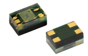 Datasheet
I will also use a small screen to show the data from the sensor
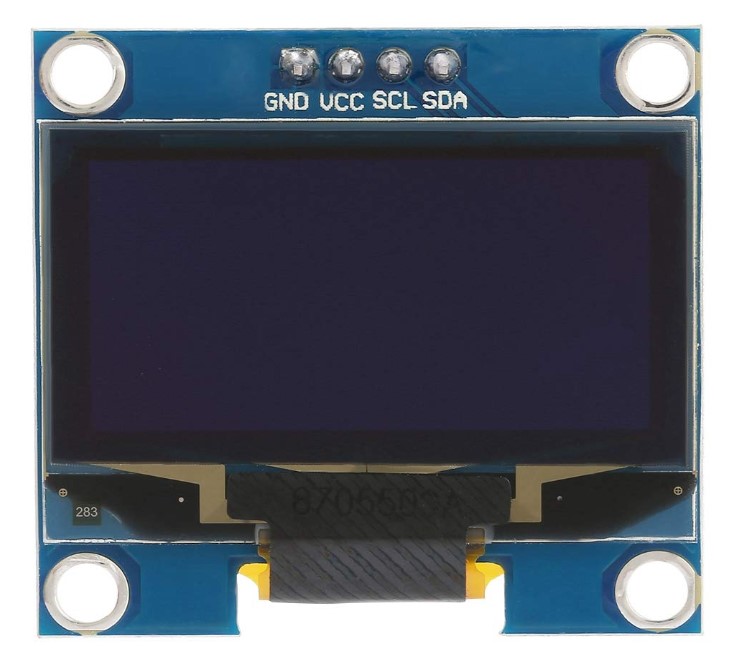
the both device use an I2C interface
Fro this week i will use a color sensor to find the color of an object
Datasheet
I will also use a small screen to show the data from the sensor
the both device use an I2C interface
I2C (Inter-Integrated Circuit ; pronounced as “eye-squared-C”), alternatively known as I2C or IIC, is a synchronous, multi-master/multi-slave (controller/target), packet switched, single-ended, serial communication bus invented in 1982 by Philips Semiconductors. It is widely used for attaching lower-speed peripheral ICs to processors and microcontrollers in short-distance, intra-board communication.Several competitors, such as Siemens, NEC, Texas Instruments, STMicroelectronics, Motorola, Nordic Semiconductor and Intersil, have introduced compatible I2C products to the market since the mid-1990s.System Management Bus (SMBus), defined by Intel in 1995, is a subset of I2C, defining a stricter usage. One purpose of SMBus is to promote robustness and interoperability. Accordingly, modern I2C systems incorporate some policies and rules from SMBus, sometimes supporting both I2C and SMBus, requiring only minimal reconfiguration either by commanding or output pin use.
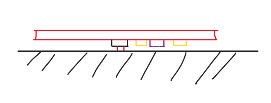
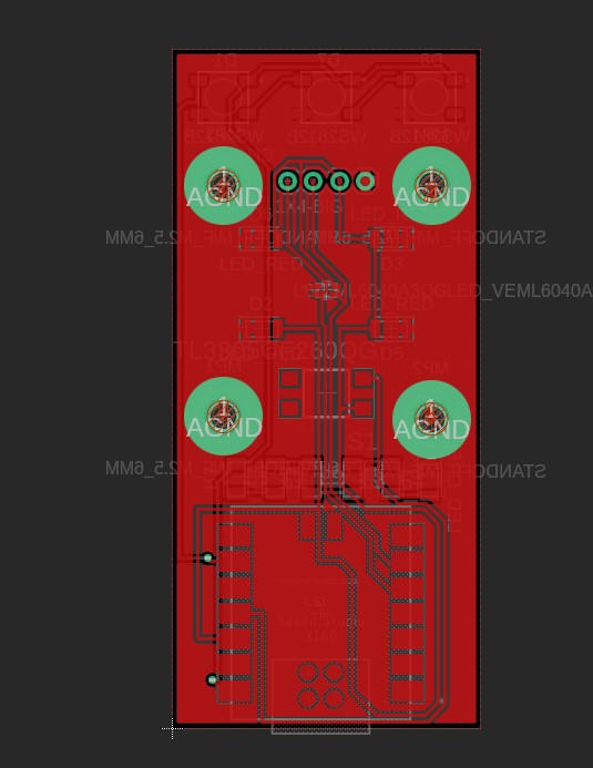
The idea is to press the PCB on an object, a botton (black) will be press against the surface to activate few white LED ( yellow) and the color sensor (purpel).
Knowing that i can design the PCB like in the week 6.
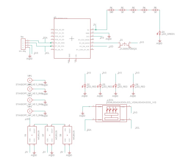
I have different groupe
On the top i have the core, with the Xiao RP2040, our brain.
Because i will use the I2C protocol i need to connect the color sensor and the screen on the pin P6 SDA and P7 SCL for the communication.
I have also the botton connect to the pin P4
and the adressable LED on pin P2 to reproduce the color we find.
Under i have defferent groupe, the LEDs, the ground connection for the holes for the stand off.
But also the color sensor, the principale sensor here.

Due to a long delay for the delivery of a double side PCB bord i didn't finish, stay tune for the update