15. Wildcard Week
Here are my files for this week- files
While trying to plan an activity for this week, our lab instructor Tom Dubick, introduced me to the idea of testing out our lab equipment on substitutes for materials. In our case, we ended up trying to make potato plastic.
Plastic Potato
On this instructables site, we were given the materials and steps to make our own plastic out of potatoes. One benefit is that it was a more eco-friendly plastic. The main ingredients included
- water
- vinegar
- corn/potato starch
- glycerin(we substitued corn syrup because it was considered a similar substitute)
- food coloring(optional)
Some of my other labmates, Dylan and Stuart, were attempting this as well. To save time, we decided to all make the material together. We also got some aluminum foil and a pan and headed over to the school kitchen.
Process
Since it was our first attempt, we decided to just go with the numbers on the page rather than multiply it by 3(since the 3 of us needed a batch).
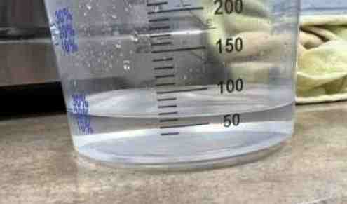
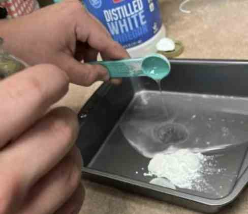
First, we added 60 ml of water with a measuring cup. We added it in the pan along with 1 tablespoon of corn starch. (We were using corn starch, since the website indicated we could). We then added some vinegar to the mix. Finally, we added 1 teaspoon of the corn syrup. We mixed it all together.
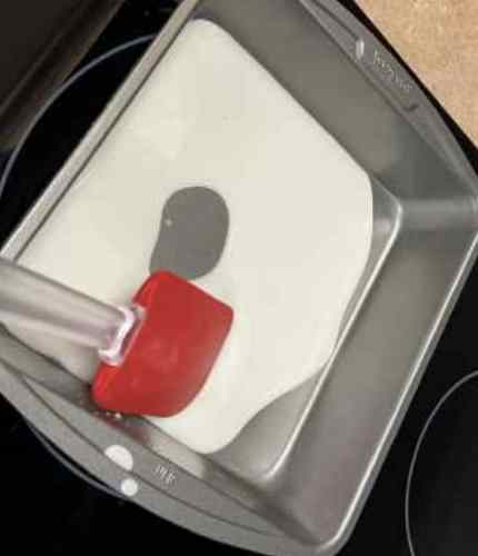
We then moved onto the heating process. We first heat it to low while mixing. Once we realized it was getting thicker, we turned it to a higher temperature, and let it sit until we could see it turned more solid.
Once we let it sit and it started smoking, we took it off and spread it onto and aluminum foil. One thing we immediately realized was that that the amount that the article mentioned is very little, so we realized we should have used more mateiral, or put it in a smaller container. What we got was a super thin layer. Therfore, we decided to do it again.
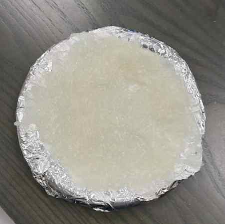
This time, we tripled the amount, along with not spreading it out as much. Here is the result.
Laser Cutting
The outcome was supposed to be a flexible, non-ripping plastic. Obviously, we had used substitutes, the outcome was quite different from what we were attempting. We let the material dry overnight, however when we came back, it was super breakable. It had turned into a solid, but it was not the flexible potato plastic it was meant to be. Our orignal plan was to have one person test milling and two people test multiple settings on the laser cutter, but since it was quite obvious that this would break and not mill at all, we all decided to mess around with our own settings on the laser cutter, with our own designs.
However, we still decieded to give our test a try. Once we had our individual batches of material, we decided to test out the engraving and vector cutting of the laser cutter. I first just started off by using CorelDraw to write my name in order to engrave it on the material.
The next thing I needed to think about were the settings. This was not the intended plastic we watned, and it was much softer and more breakable than what we had attempted, so I had to be careful that I don’t set the power too high.
I looked up some settings on the 120 watt epilog pro. Here is a link to the chart
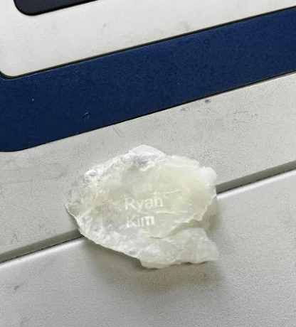
I set the engraving settings, and I ran the cut. To my surprise, the letters showed up quite clearly. However, one thing I realized was that the engraved letters started to fade once we took the material out. Here is an image a little bit after it was taken out. I ran it twice, first a test, then with a more appealing font.
This is a video of engraving on the box I cut, which is what I tried next
The next thing I tried was vector. Again, I took similar measures to rubber and silicone. I made a rectangle with a fancy font with my name on it, and tested to see if it would cut. The first cut did not cut well, so we slowed down the cut a bit on our second try. This one cut out well. Here is an image of the box with my name on it.
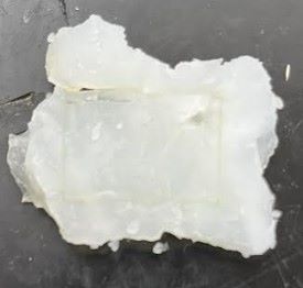
Failed Cut
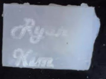
Successful Cut with my name engraved
Shop Bot Rotary Index
Though the custom plastic laser cutting experiment was a good test and expereince, I wanted to attempt to learn something else. My labmate Dylan introduced me to a tool I didn’t know even existed. Our lab contained the Index Rotary for the shopbot, and Dylan set it up on the shopbot. He taught me what it was used for, and so I decided to attempt to learn how to use it.
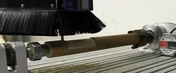
Here are images of the inital setup.
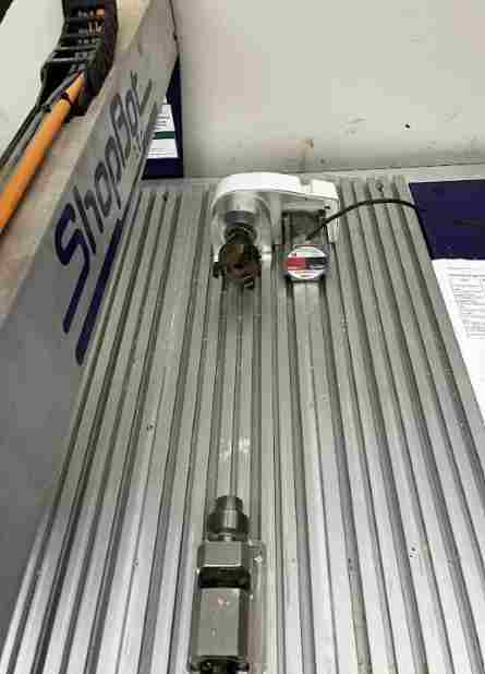
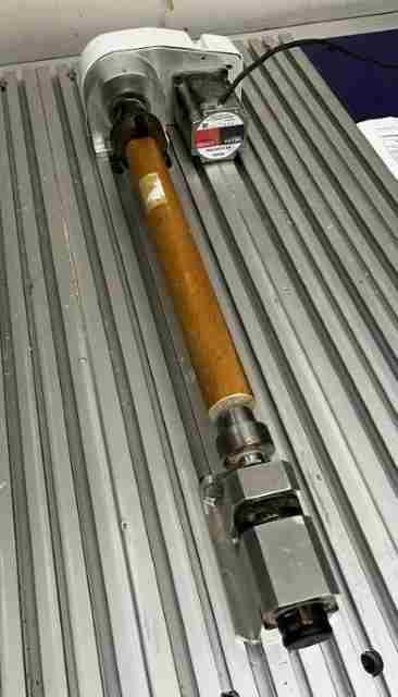
Once we had it set up, we ran the command MB, 90 on the control software to see if it would move, and it did.
Test 1
First, as a group, Stuart, Dylan and I decided to run a test cut. Me and Dylan set up the dowel and zeroed the machine on the front, top, and center of the dowel, which was how we set it up in Aspire. Stuart set up the Aspire file, with simple pocket cuts wrapped around the rotary toolpath.
Once we had everything set up, we decided to run an aircut. We set the x-zero to 10 inches to the left, so that we could see if the rotary index was spinning along with the shopbot. It did, and the bit seemed to mover where we expected, so we began the cut.
At first, it looked like a success. However, we soon came to realize that the toolpath didn’t work out. The cutting wasn’t super accurate, and we got an unexpected outcome that looked like this.
Initially, it looked good
But it ended up being incorrect
Test 2
I did this individually, since I wanted to attempt it. Since our first test cut didn’t work, I figured it might be an error in the toolpath. I therefore went online and found this video that shared how to import an STL file and create the necessary toolpath for the CNC rotating axis.
I first desgined it in Fusion 360. It looked like such, since I was attempting to make a table leg.
I then imported the STL file into Aspire, and created the job size. I got a dowel, measured the diameter and length, and entered it in. For the length, it was around 11 inches, but I put in 9 inches, since I had to be sure not to cut into the actual rotating motors. My table leg was around 8 inches in length.
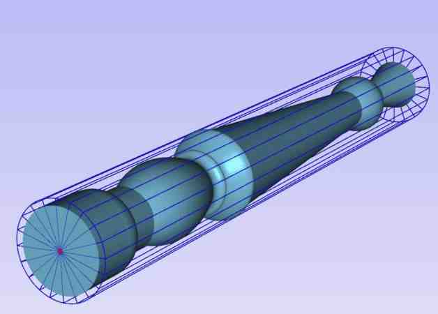
I realized while watching the video that he was doing a roughing and finishing path. I wanted to get an outcome, but first, I needed to see if the toolpath even worked. Therefore, I only did the roughing pass with a 1.4 inch bit. One error I came to realize was that when setting up the toolpath, I set the boundaries to the job size, not the actual cut. Therefore, wehn I simulated the toolpath, I saw that it was cutting off the edges, which would be a problem because the edges are necessary to hold the dowel, and if I cut off the edges, it would fall during the cut. Therefore, I went back and changed this error.
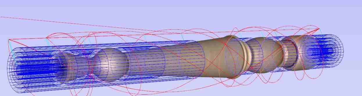
Here you can see the 2d view.

I previewed the toolpath, and it looked about right. I sent it over to the computer next to the Shopbot. We were using the Shopbot desktop. I again zeroed the z-axis and y-axis. I offset the x-axis to run an aircut to make sure it wasn’t going where it is not supposed to. Once evrything was checked, I ran it again on the actual x origin. I kind of had to eyeball this, but Dylan gave me a good idea, in which I put the bit right next to the side of the dowel, and in that position, I then move it to the middle by dividing the diameter of the dowel in two. This way, it can be as close to the center as possible.
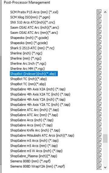
After setting up the toolpath, I had to set up the post processing. I found the Index Machine in the post processing option, saved the file, and then sent it to be cut.
Here is a video of this version cutting.
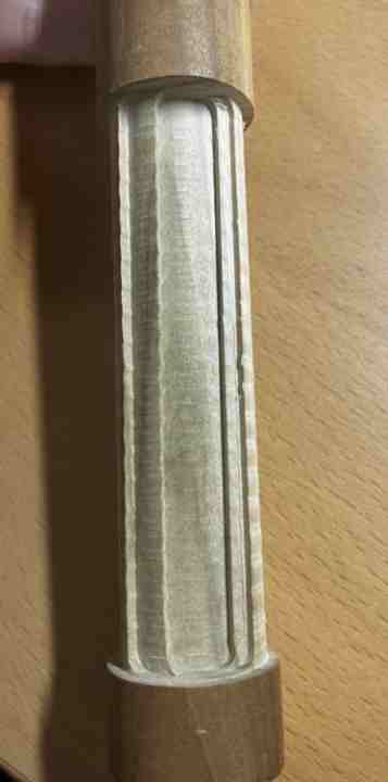
The rotations moved fine, the positioning was fine, however I ran into the same problem. Everything worked great, but the machine didn’t cut what it was supposed to. I double checked I had the Shopbot Indexer option checked in Aspire in Machine Configuration, and double-checked I had the right file. Everything looked good. Stuart ran his cut after mine, and his also ran into the error. We recognized that the cut was different, so it definitely wasn’t an error in the files. However, it just wasn’t cutting the right way. I looked at this video to see if we were missing anything in the setup, but we did everything that was necessary. We therefore concluded that something about the setup in Aspire and the rotary motor we had setup did not match. Either the driver for the motors were outdated, or there was a step we missed in the setup process.
Though the cut was unsuccessful, we were able narrow down the fact that the issue lies within the G-Code and the connection of the index with Aspire’s CAM process.
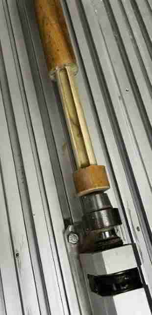
Here is an image of the cut.
Reflection
This week was a fun week. Prior to my experiment with the potato plastic, I did not recognize the versatility of our Epilog Laser Cutter. I attempted to make a custom material, and though the material didn’t exactly fit the desired outcome, I was able to use my laser cutting skills to make something out of it. As for the CNC 4th axis attempt, though our cuts may have been unsuccessful, I am still glad I attempted this. Through this process, I was able to learn more about Aspire, and the options for setting up a different kind of toolpath in a totally different job setup. I have only ever cut 2D toolpaths, and though that is a great skill, I always wanted to learn more about the big milling machines. I had not known this was option for the rotary index even existed. Again, I was able to experience a deeper dive of the amazing capabilities of the machines in our lab, and I have learned a lot of things this week.