Prefab Work
Prefab Documentation
Surface Mount Soldering
We began our journey by practicing some surface mount soldering. This was a new form of soldering where you put on the pieces on a board and connect it with solder. We took a big 555 chip for suface mount soldering practice, where we soldered on a bunch of transistors, resistors, and more. I first applied solder to the pads, and used a tweezer to place the tiny components and melted the solder so it would stay on the surface.
ATTiny 412
Through this project, I was able to learn the basics of uploading a programmer to an Arduino, and using a microcontroller to set certain pins to do certian things.
jtag2updi
I was able to use the jtag2updi tool to bring code to the ATTiny412 while using the Arduino Uno as a programmer. First, I brought in the jtag program into the Arduino IDE, and I had to set the board to Arduino, not the 412! I was setting the Arduino as a programmer, so I first uploaded the jtag code to the Arduino once I had my com port selected and my arduino connected to the computer.
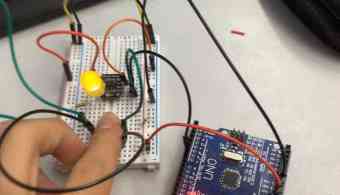
Blinking The LED
Once I had jtag2updi uploaded, I opened a new folder where I would code a blinking LED. This time however, I would have to change the board to the ATTiny, because that is what is running code to the LED. I set programmer as jtag2updi, and then opened the blink example from the IDE. Using the pinout sheet for the 412, I connected pin 6 of the ATTiny to pin 6 of the Arduino, which is how it would communicate. I then connected power and ground of the Ardunio to the Attiny. I connected the LED to one of the pins, then a resistor going to ground. I would code the OUTPUT pin of the LED with the correponding pin it shows on the sheet.
void setup() {
  pinMode(2, OUTPUT);
}

void loop() {
  digitalWrite(2, HIGH);
  delay(100);
  digitalWrite(2, LOW);
  delay(75);
}
Button as an Input
My next step was to create an input button to control the LED. It was pretty simple, I just ketp the same blinking circuit but added a button that linked to another pin, which I would set as input.
Here is the code for that.
pinMode(pinnumber, OUTPUT);
pinMode(pinnumber, INPUT);
I then coded it so that if a signal from the input button is recieved(the button is being pressed) then set output pin as high(turn LED on). I used a pull down resistor so that if the button was not pressed, the power going into the button went to ground through a load.
ATTiny412 Summary
It was cool to learn about microcontrollers and learn how to sue them so they can do more rather than to just connect an LED to a resistor and turn it on. With the knowledge I had gained, I was able to do more, such as two buttons and two LEDS(just connect them to more pins and code it as such). I even included a photoresistor into an analog pin(use pinout sheet) so that if it was a certain brightness, the LED would turn on and off.
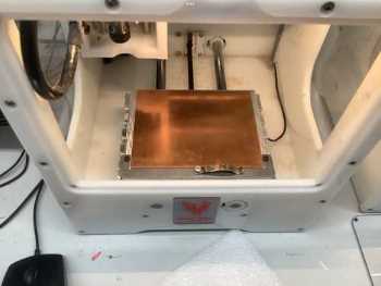
Milling
I learned the basics of using the Bantam Tools milling machine. This was a bit more complicated then the 3d printer of laser cutter to me, for there were a few more steps. I followed a workflow to figure out how to get a cut going. One mistake I made was not knowing to use metal holding piece when calibrating, which is how it knows where to position the calibration. I used differnt bits for the traces/holes and the outline.
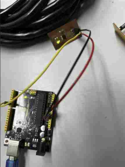
I then soldered on a 412 along with headers, an LED, a resistor, and a capacitor. (Surface Mount Soldering)
I connected it to the Arduino Uno the same way as before, using the Arduino as a programmer. The milled circuit was the same, pin 6 to 6, ground to ground, and power to power, so I just got three wires and conencted it.
Positive Ground
The circuit used a positive ground. Vcc is connected to LED at all times, and the ATtiny controlled the other side and changed it to high or low. Because it turns on in a difference of voltage, in the code, we had to se the out put as low in order to turn the LED on.
void setup() {
  pinMode(2, OUTPUT);
}

void loop() {
  digitalWrite(2, LOW);
  delay(1000);
  digitalWrite(2, HIGH);
  delay(1000);
}
digitalWrite(2, HIGH);
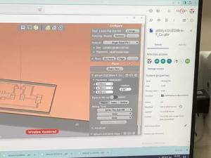
Fusion 360
Fusion 360 is a high-performance software with so many great tools that it would take more than a year to master all of them, such as designing, animating, creating electronics through a built in software called Eagle, CAM, and much more. It is a great software that would help me significantly in my high school engineering experience. To prepare for using this software, I followed Product Design Onlines, Fusion 360 in 30 days tutorials to familiarize with some of the tools, which helped me significantly when trying to make my own Fusion projects.