Computer controlled cutting
Introduction:
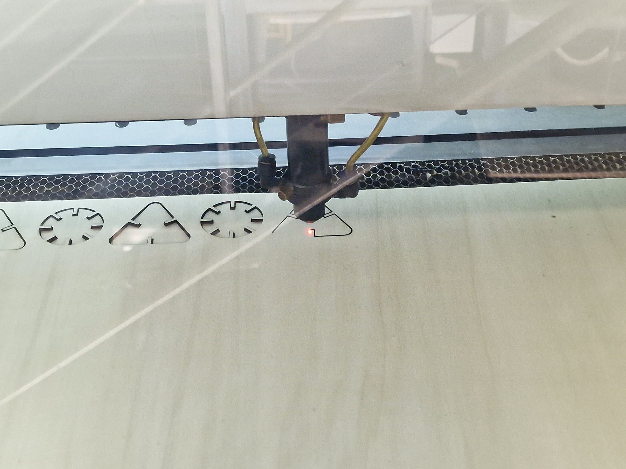
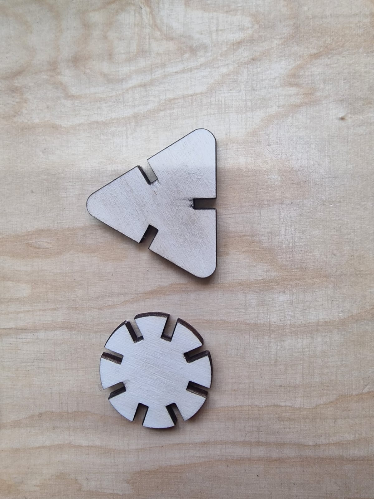
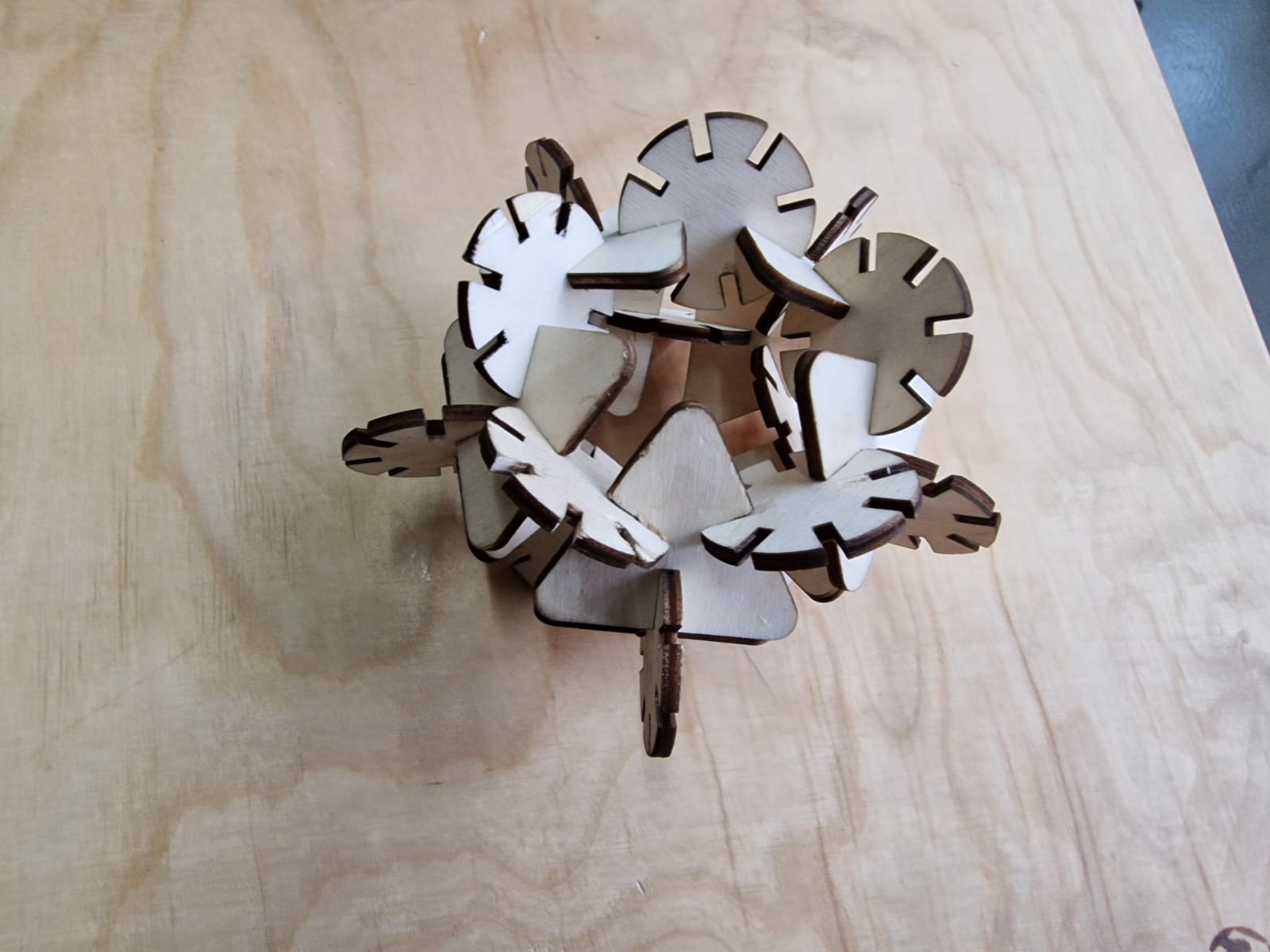
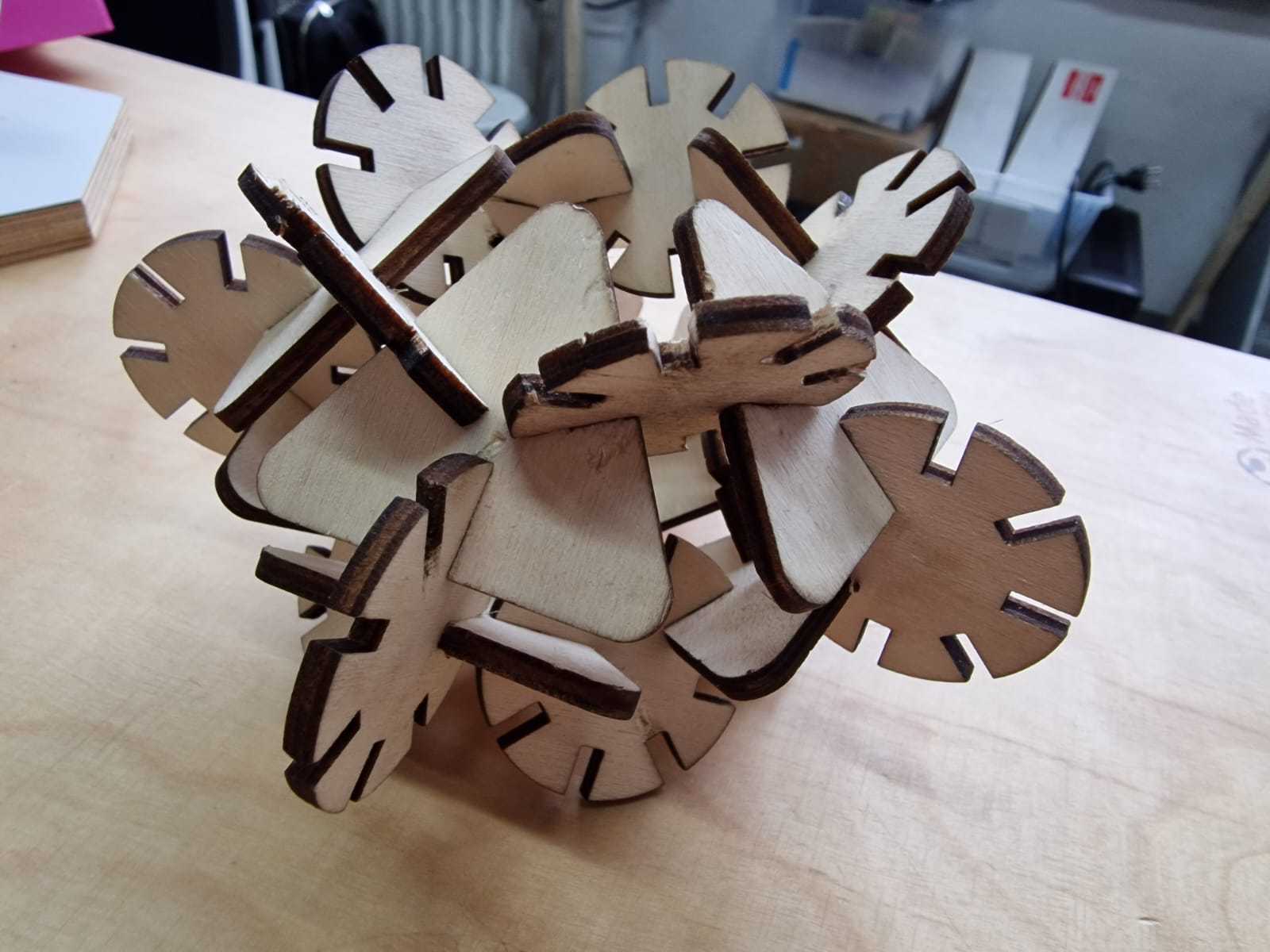
For the individual assignments, I have designed, lasercut, and
documented a parametric construction kit with the consideration of
lasercutter kerf. The objective is to create a versatile assembly system
using two fundamental geometries—circles and triangles. By strategically
introducing gaps at different positions, the components can be
fit-pressed in multiple ways to achieve a variety of constructions.
Research:
Computer-controlled cutting (also known as CNC cutting) is the process
of using a computer-controlled machine to cut, carve, or engrave
materials with precision and accuracy. This technology is commonly used
in various industries, including manufacturing, construction, and
design.
The machine used in computer-controlled cutting is called a CNC router,
which is typically controlled by software that allows the user to design
and input the desired pattern or shape to be cut. The machine uses a
cutting tool, such as a router bit or laser, to cut the material
according to the programmed design.
Computer-controlled cutting can be used on a variety of materials,
including wood, plastic, metal, and even fabric. It is commonly used in
the production of furniture, cabinetry, signs, and other decorative
items, as well as in industrial manufacturing for precision cutting and
shaping of metal parts.
Design process:
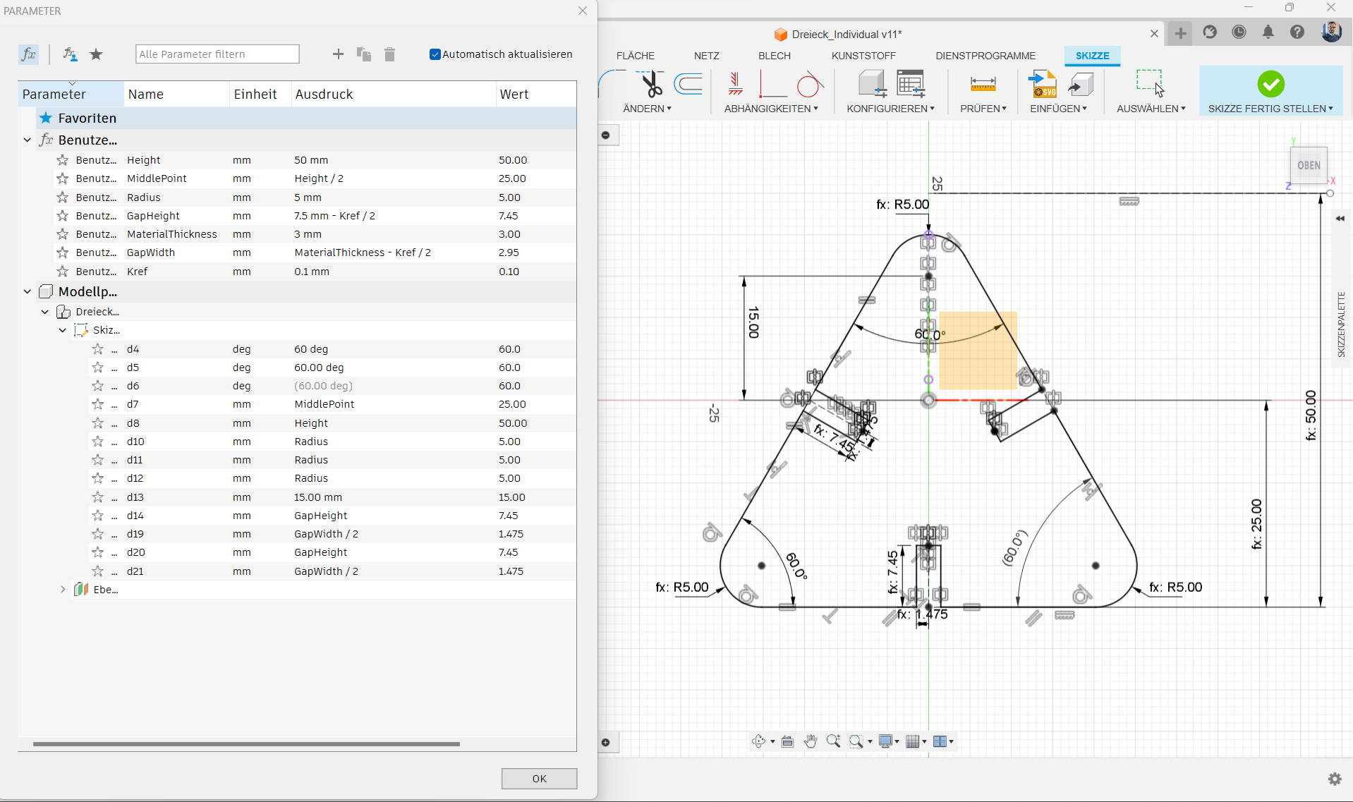
1. Triangle Design:
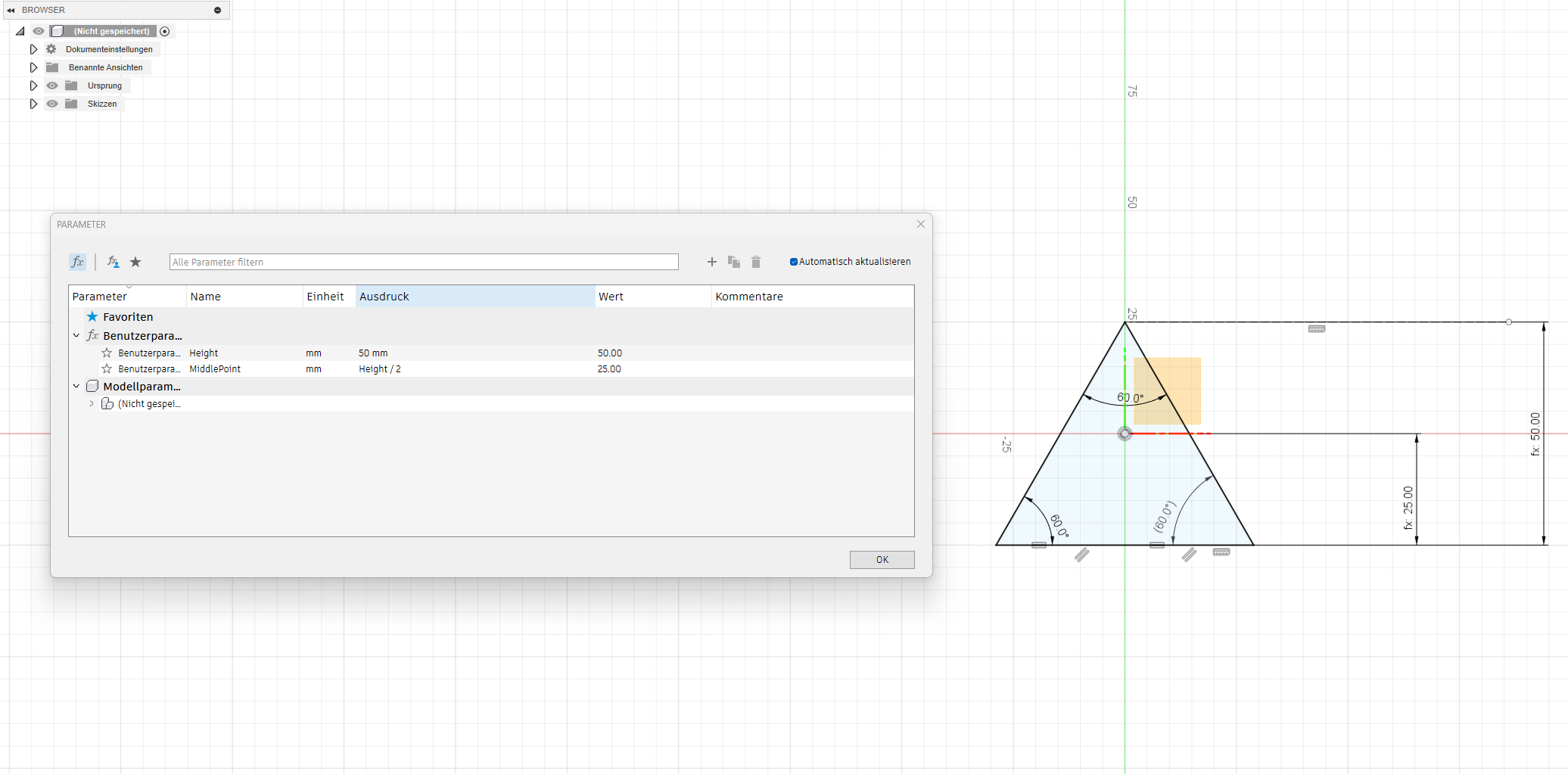
I initiated the process by sketching a triangle, defining its "height"
and "middlePoint," and establishing a mathematical relationship between
these two crucial measurements. To enhance parametric flexibility, I
utilized the user parameter function in Fusion 360, incorporating
parametric values for these measurements. To accommodate the lasercutter
kerf, I implemented the kerf value in other measures, particularly on
the external contours, keeping the initial value at "0" until the
lasercutter machine's kerf characterization.
2. Corner Rounding:
To enhance user safety during assembly, I incorporated rounded corners
in the triangles. The rounding parameter, denoted as "Radius" in the
user parameters, was set at 5 mm.
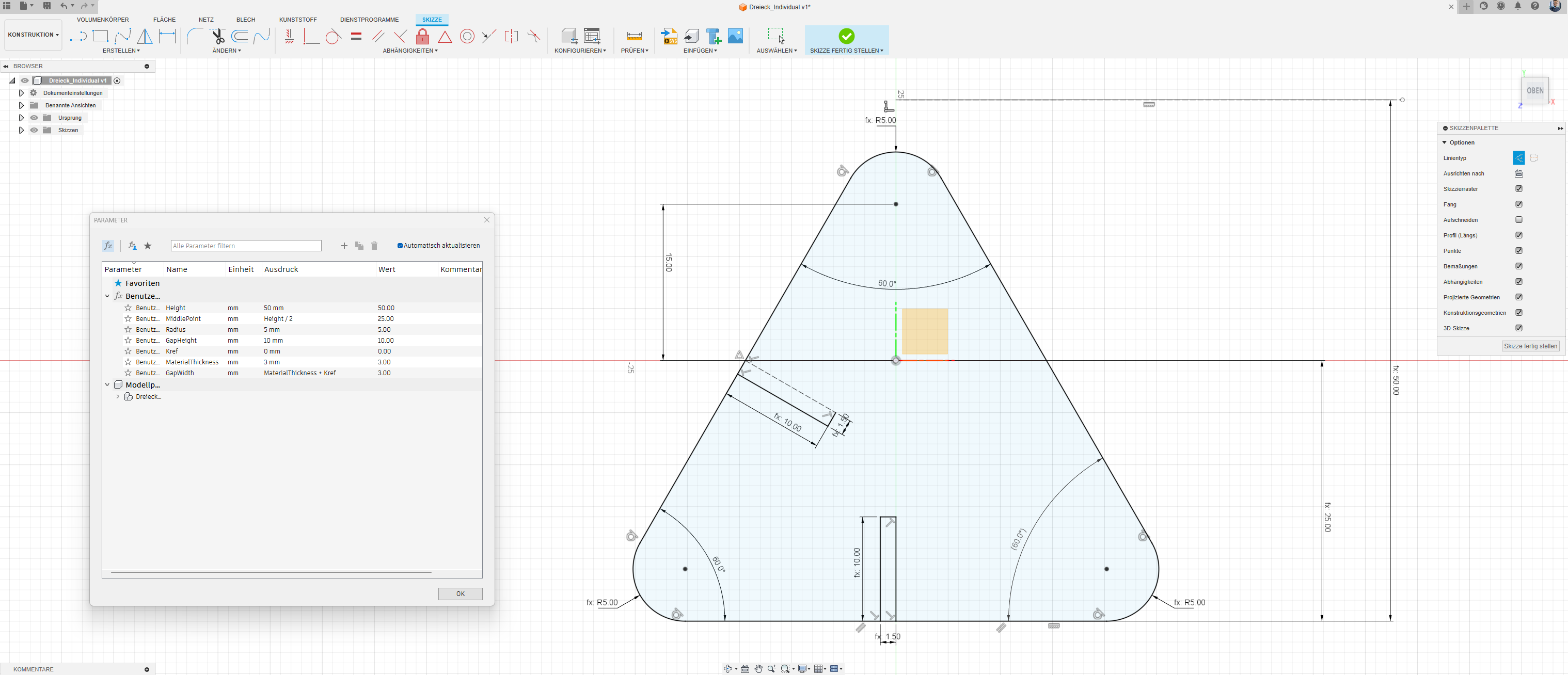
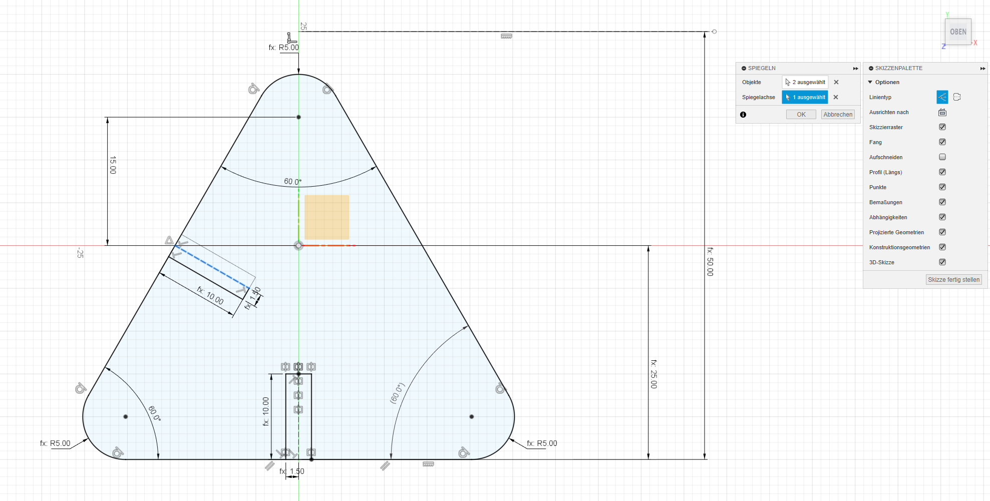
3. Rectangle Addition:
Subsequently, I introduced two rectangles—one at the center of the base
and the other on the left side. These rectangles are parameterized as
"GapWidth" and "GapHeight," with "GapWidth" aligned with the
"MaterialThickness." Similar to the triangle, considerations for the
lasercutter kerf were applied.
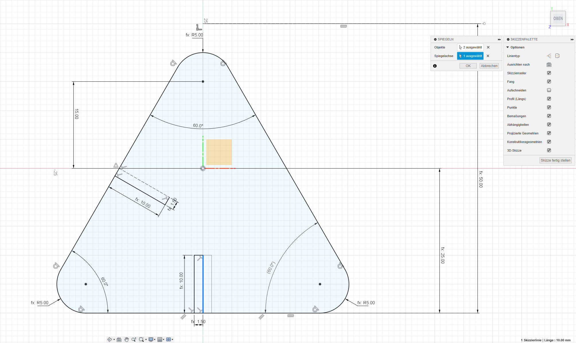
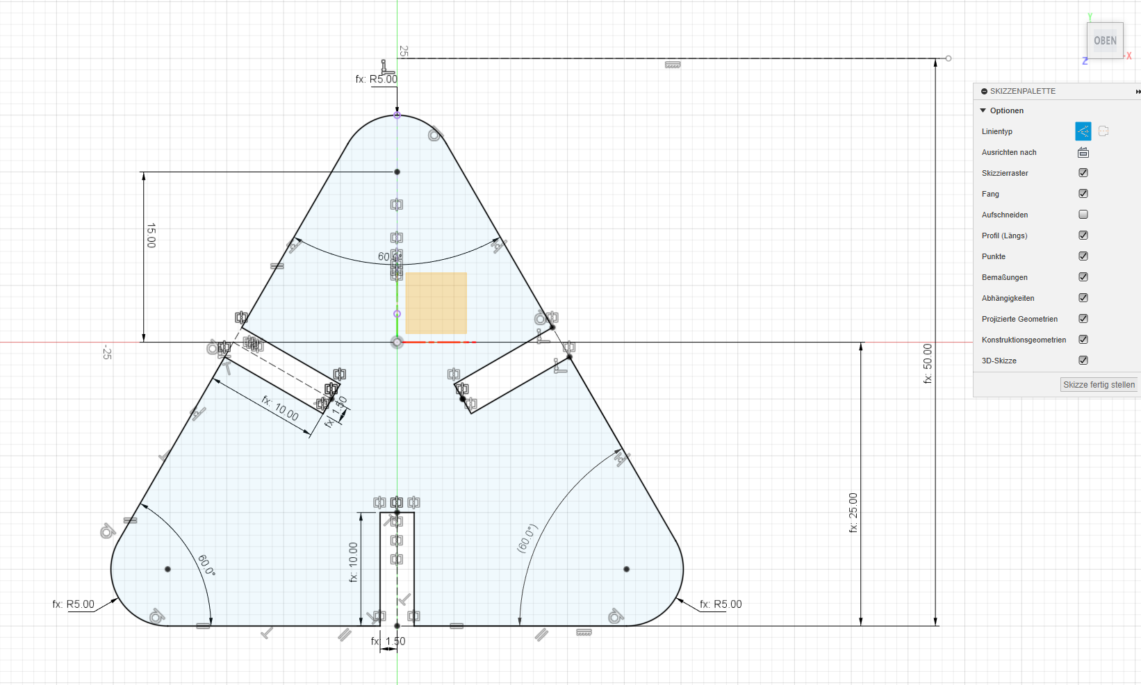
4. Mirroring:
To ensure uniformity, I mirrored the rectangles along each of the three
sides of the triangle.
5. Gap Creation:
The next step involved cutting unwanted lines, creating the necessary
gaps for the press-fit construction , with adjustments made to account
for the lasercutter kerf.
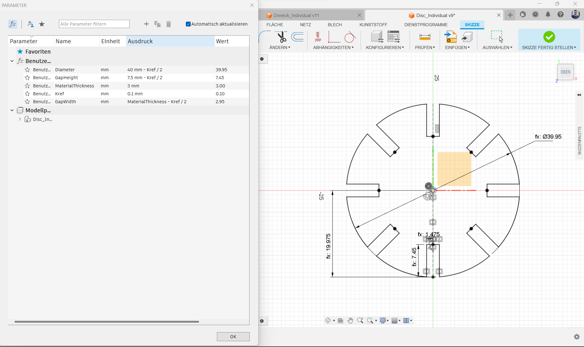
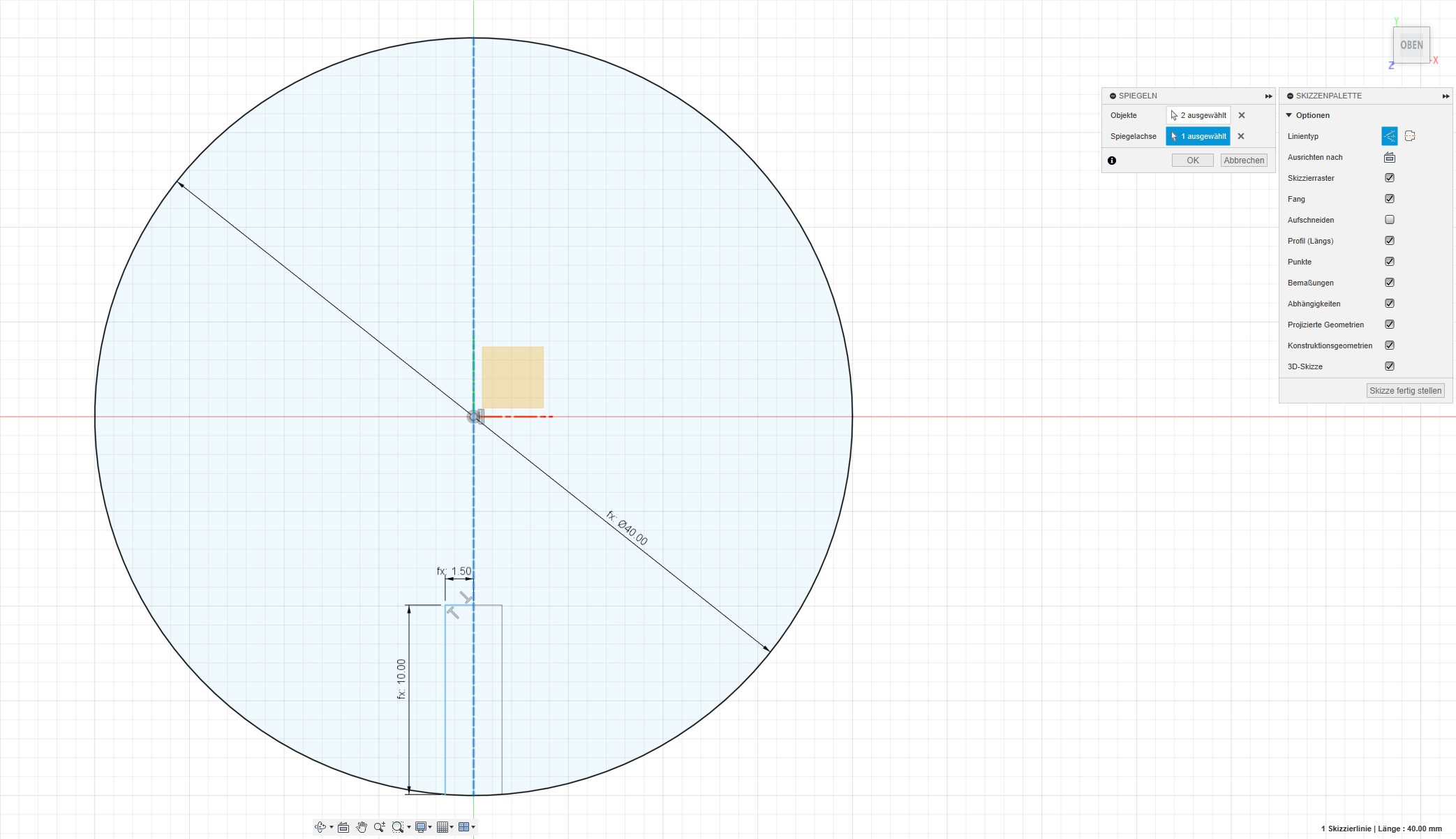
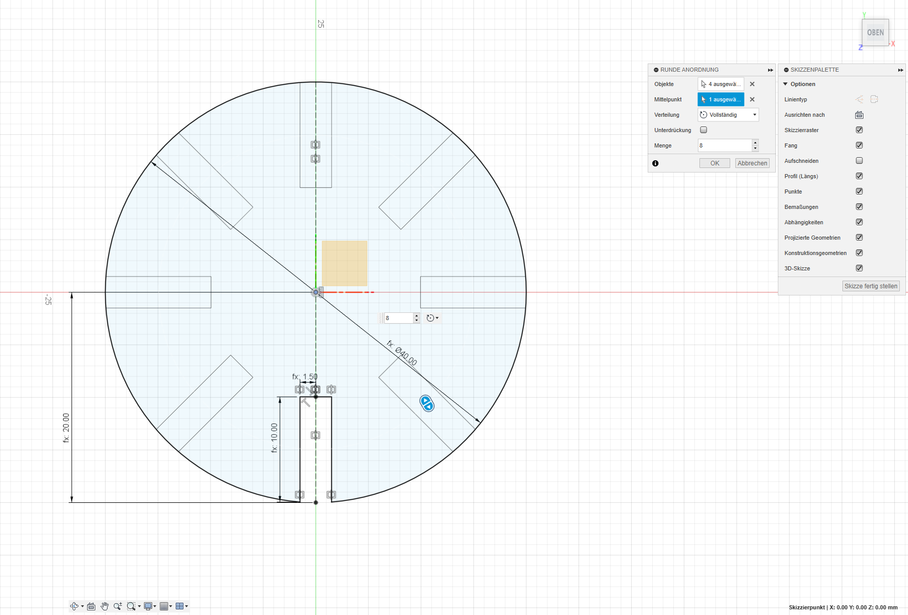
6. Circle (Disc) Design:
Replicating the process for the circular component, I set gap parameters
to match those of the triangles. Considering the lasercutter kerf,
adjustments were made to measures, especially on external contours, with
the initial value set at "0" until the lasercutter machine's kerf
characterization.
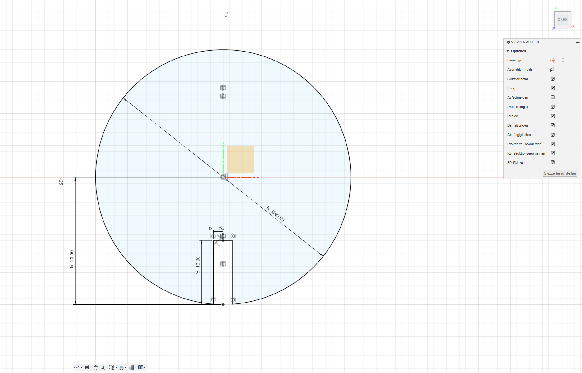
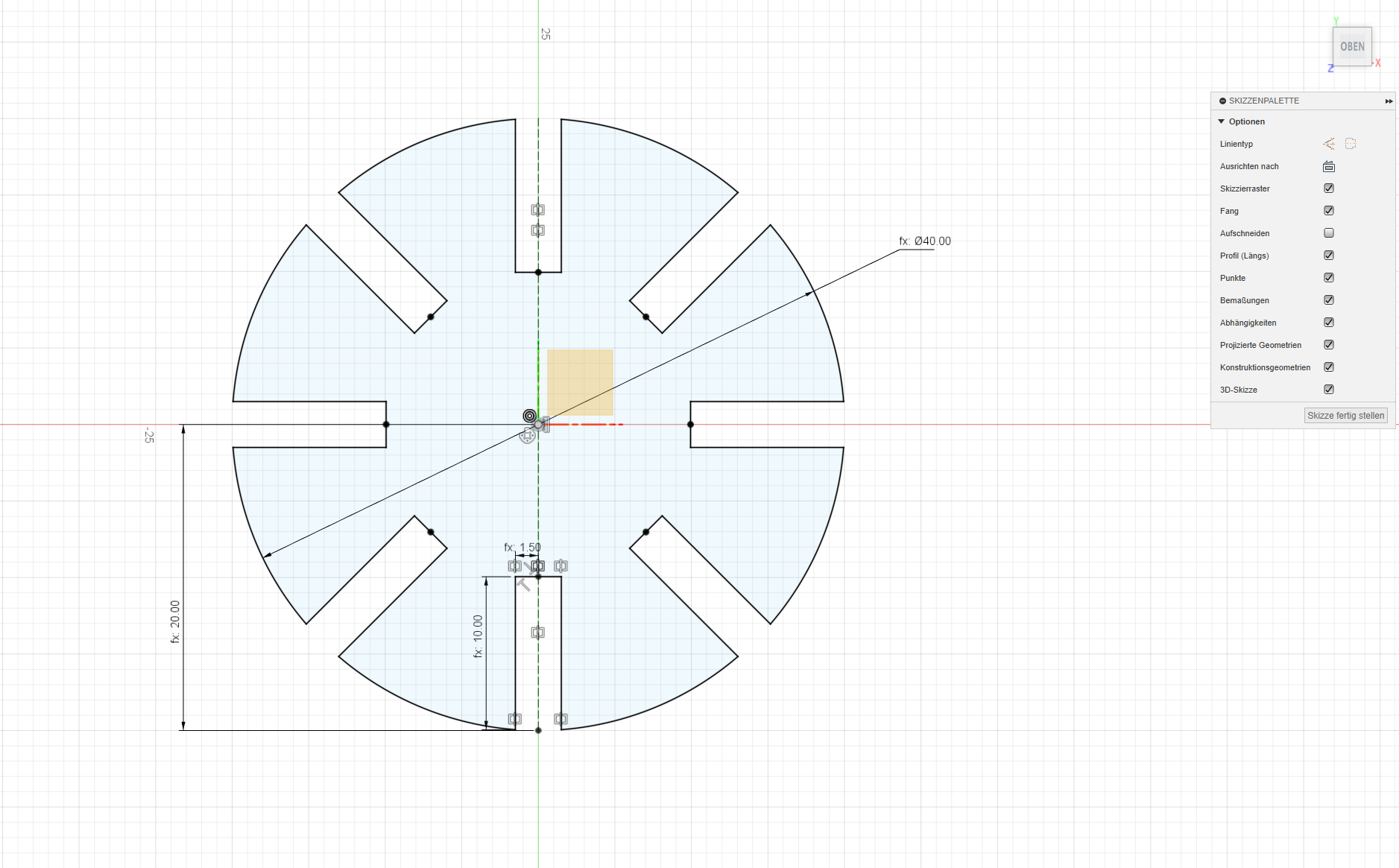
7. Gap Refinement:
Final adjustments were made by cutting away unnecessary parts of the
circle, creating the essential gaps for the press-fit construction.
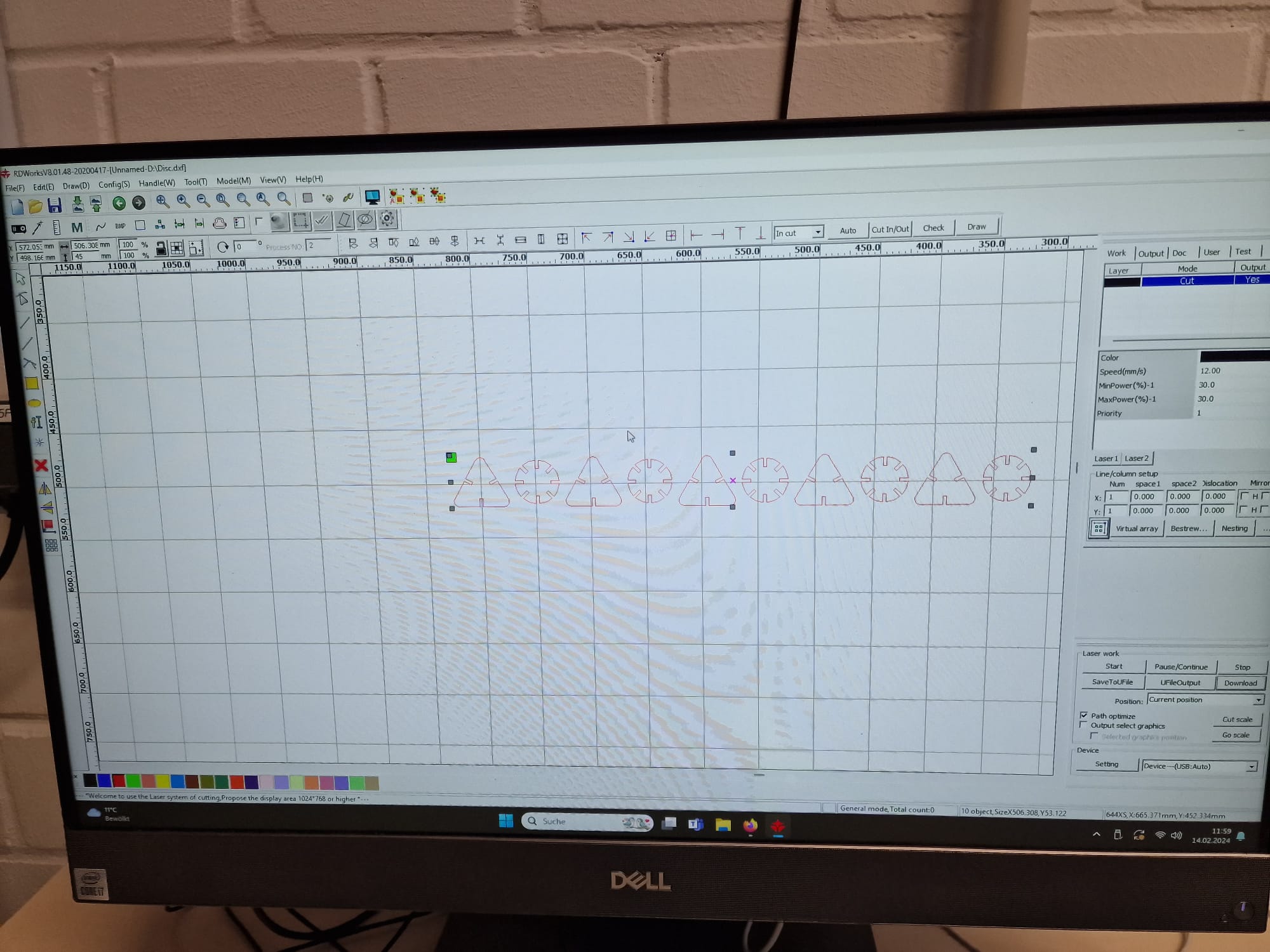
7. Finalizing the parameters for cutting: