9. Output Devices
assignment
   individual assignment:
      add an output device to a microcontroller board you've designed,
         and program it to do something
   group assignment:
      measure the power consumption of an output device
individual assignment:
In this week I wanted to control different mini stepper motors, which I want to use for the xyz-table in my final project.
I used a A4988 stepper-motor-driver to control the stepper motors. The pins 1A and 1B have to be connected to the first coil and 2A and 2B have to be connected to the second coil of the stepper motor. I think it is not important that you place A and B in the right pins – if it are the “wrong” pins the motor will turn in the opposite direction. If the direction is important for you, of course you should use the right pins or you can change the rotational direction in the code. You can find out which cables belong to one coil by measuring the resistance between two cables. If there is infinite resistance the cables do not belong to the same coil.
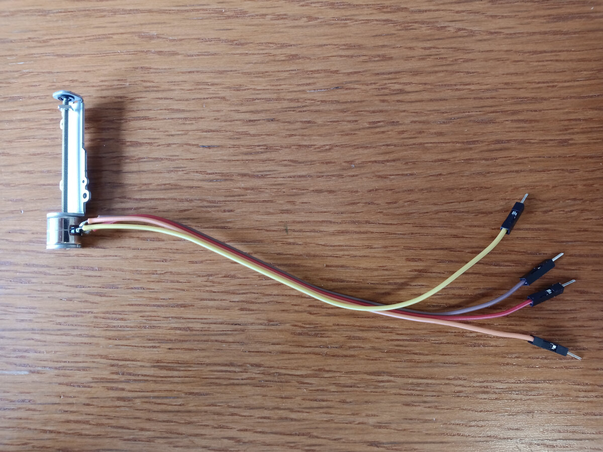
Micro stepper motor. These stepper motors were delivered without a nut. I tried to mount a nut by bending the upper metal part of the frame backwards, inserting a M2 nut and bend it back. It worked, but I think the motor is not running as smoothly at it did before this treatment. I also tried to mount a plastic M2 nut by cutting it open and placing it on the lead screw, but it sit so strong on the screw that if I tried to fix its rotation the motor was not able to rotate the lead screw any more.
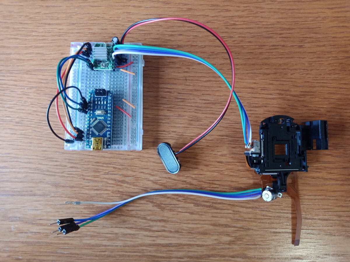
Here you see a micro xy-table, which could be used to position a nanodiamond into a focused laser beam.
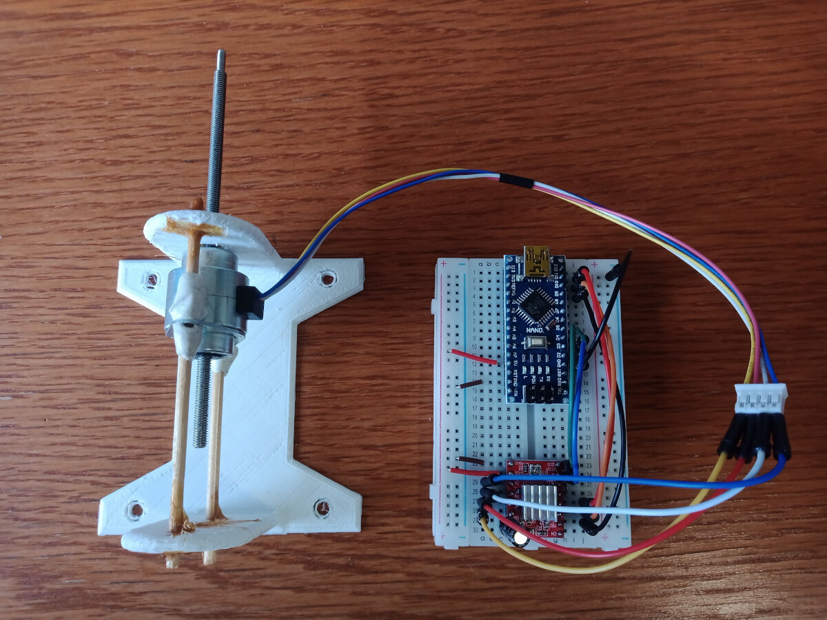
Left you see a non captive stepper motor. With this kind of stepper motors the lead screw moves forward and backward, if you prevent it from turning. I prevent the lead screw from turning by placing it directly next to the white 3D print, so that the lead screw contacts it a bit. This stepper motor is meant to move a magnet towards and backwards to the quantum sensor, which shall be capable to measure the intensity of the magnetic field.
Here you find very good tutorials on how to control stepper motors with an arduino:
https://www.youtube.com/watch?v=7spK_BkMJys&t=2s
https://zerotohero.engineering/setting-vref-for-drv8825-and-a4988-motor-drivers/
First I used this code without using a library:
uint8_t stepPin = 2;
uint8_t dirPin = 3;
int steps = 3200; // one rotation with sixteenth step mode
int usDelay = 100;
void setup() {
Serial.begin(9600);
pinMode(stepPin, OUTPUT);
pinMode(dirPin, OUTPUT);
pinMode(9, OUTPUT); // Microstepping: sixteenth step mode
pinMode(10, OUTPUT);
pinMode(11, OUTPUT);
digitalWrite(9, HIGH);
digitalWrite(10, HIGH);
digitalWrite(11, HIGH);
}
void loop() {
digitalWrite(dirPin, HIGH); // motor direction cw
for(int x = 0; x < steps; x++)
{
digitalWrite(stepPin, HIGH);
delayMicroseconds(usDelay);
digitalWrite(stepPin, LOW);
delayMicroseconds(usDelay);
}
delay(1000);
digitalWrite(dirPin, LOW); // motor direction ccw
for(int x = 0; x < steps; x++)
{
digitalWrite(stepPin, HIGH);
delayMicroseconds(usDelay);
digitalWrite(stepPin, LOW);
delayMicroseconds(usDelay);
}
delay(1000);
}
Then I used the AccelStepper library, which allows you to easily change acceleration and deceleration, direction, speed, steps and much more:
http://www.airspayce.com/mikem/arduino/AccelStepper/
Further, I used my Attiny85 microcontroller board from week 8 (
) to controll a 28byj-48 stepper motor. The Arduino in the image was only used as power supply:
Here you can find the Arduino code:

#include <AccelStepper.h>

// Define a stepper and the pins it will use
AccelStepper stepper(AccelStepper::HALF4WIRE, 1, 3, 2, 4);

void setup()
{
  // Change these to suit your stepper if you want
  stepper.setMaxSpeed(500);
  stepper.setAcceleration(400);
  stepper.moveTo(500);
}

void loop()
{
    // If at the end of travel go to the other end
    if (stepper.distanceToGo() == 0)
      stepper.moveTo(-stepper.currentPosition());

    stepper.run();
}
it is based on the example bounce from the AccelStepper library.
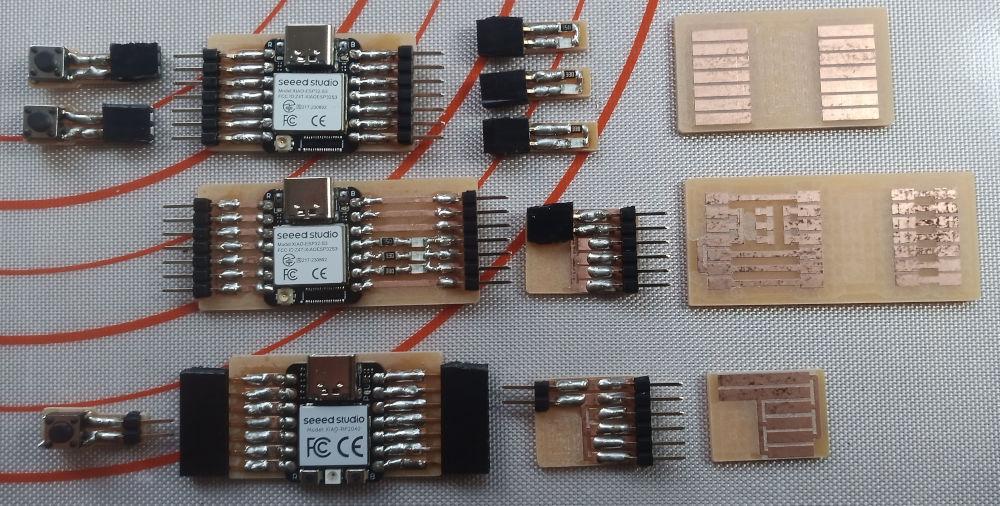
Further, I fabricated breakout boards using Xiao µC
This is a very powerful µC. Actually, we use it in the practical training "Embedded Systems" for Artificial Intellgence applications.
On the left of this board you see two mini-boards with buttons you can directly connect to the board.
On the right of the board you see three mini-boards with led you also can connect to the board.
Far right you see the bare pcb of the board.
In the second row you see the same board with additional three (red, green, blue) leds directly on the board.
Right from the board there is a mini-board to expand the 3.3 volt and GND pin from one to three pairs.
Far right you see the raw pcb of the board.
In the third row there is a basal breakout board with a cheaper but also less powerfull XiaoRP2040.
To this board I attached femal pin headers.
On the left and right to the board you see the mini-boards with a button and for more 3.3V and GND pins, but with male pin headers.
I wanted to try out which version works better, so I tried out both versions.
On the far right you see the bare pcb of the mini-board to expand the 3.3 V and GND pins.
The "board systems" is inspired by the system made by Adrian Torres:
https://fabacademy.org/2020/labs/leon/students/adrian-torres/fabxiao.html
The design files for all boards you can download under the following link:
For this week I also used the first board to attach it to a stepper motor.
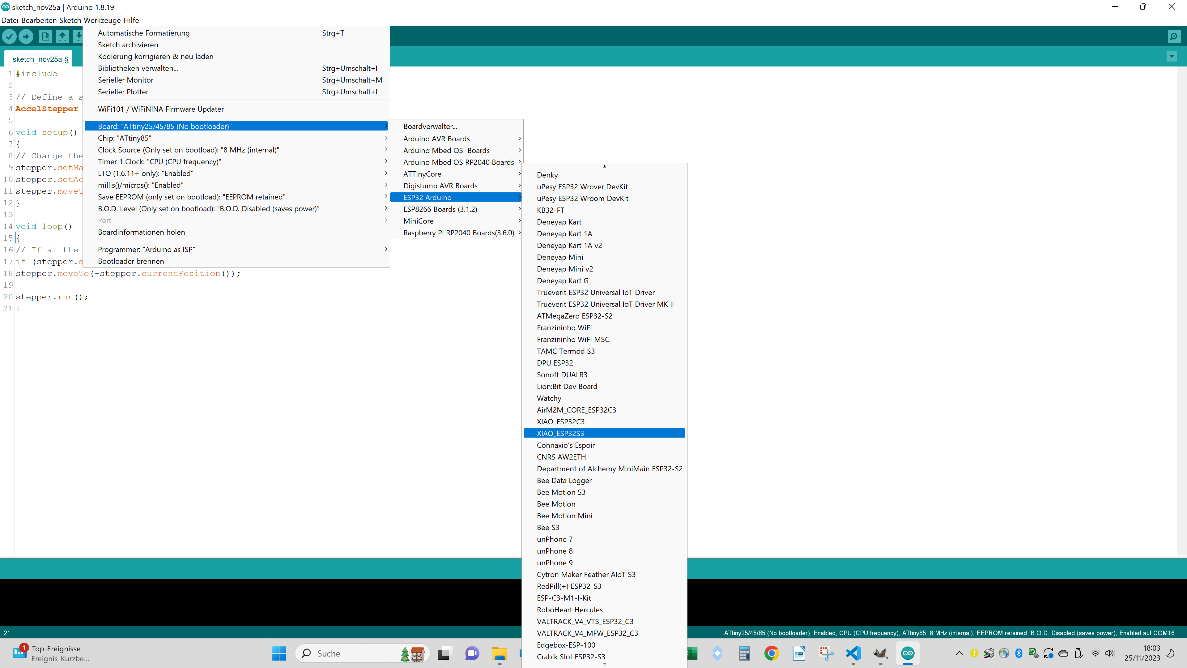
Here you find a good explanation how to use the XiaoEsp32S3 Board with the Arduino IDE:
https://www.youtube.com/watch?v=_wvuOsRgmt4
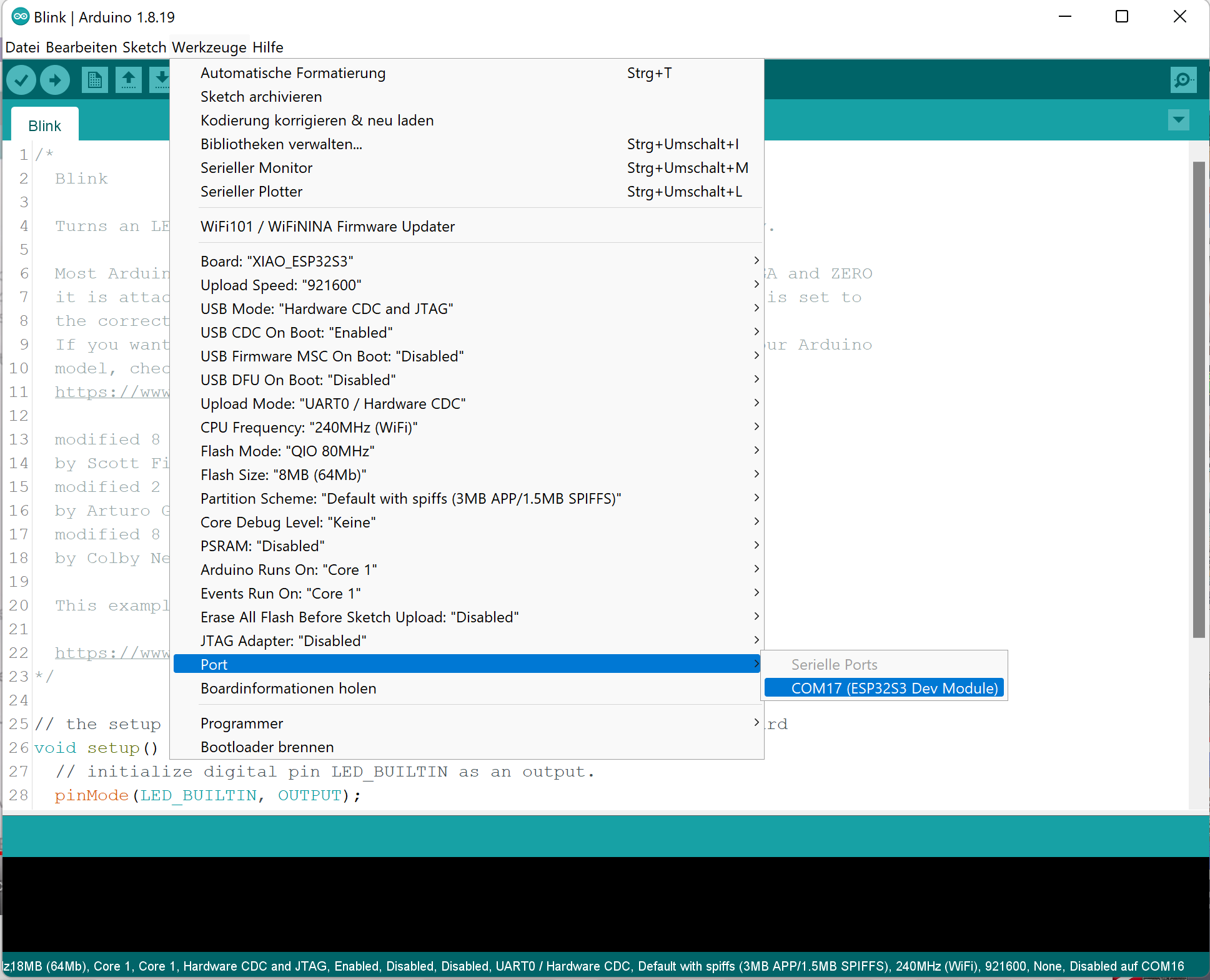
After installing the ESP32 Board choose Xiao_EPS32S3 als Board and the and the corresponding com connection:
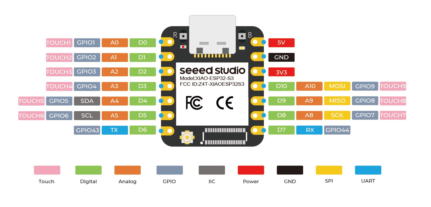
I used the GPIO Pins 9, 8, 7 and 44. In the code you have to switch the order of the two middle pins when allocating the pins to the IN pins of the stepper motor driver. When the UBS port of the Xiao_EPS32S3 is connected to a suitable power supply you can draw power from the 5V pin to power the stepper motor.
Here you see the stepper motor slowly moving in one and then in the other direction. I used the same code as shown above except of the pins allocation.
group assignment:I measured the power consumption of the first stepper motor by inserting a multimeter in the circuit of one coil. Without a load the motor draws only about 15 mA.
The code above switch the rotational direction after one rotation, so the multimeter showed alternatively about 15 and -15 mA.
Then I measured the voltage parallel to one coil. I measured about 800 mV, but I am not so sure with this measurement, because I thing the stepper motor suffers from my treatment mentioned above.