Interface & Application programming.
Group assignment: compare as many tool options as possible.link to group assignment is here.
Individual Assignment
Write an application that interfaces a user with an input &/or output device that you made.
Processing.
According to snap AI; Processing is a programming language, development environment, and online community. It is used by artists, designers, researchers, and hobbyists for learning, prototyping, and production. Processing is an open-source project and is free to download and use. OR Processing is a tool that allows people to create interactive art and design projects using code. It's like a paintbrush, but instead of painting with colors, you're painting with code. Processing can be used for a wide range of creative projects such as creating interactive art installations, generative music, data visualization, and educational tools. It can also be used for prototyping and developing software applications.
link to download the processing software is here
Difference between Processing and arduino .
1. Arduino IDE is primarily used for controlling hardware, while Processing is primarily used for creating multimedia projects.
2. Arduino IDE uses C++ programming language, while Processing uses Java programming language. 3. Arduino IDE requires an Arduino board to run the code, while Processing can run on any computer. 4. Arduino IDE is more focused on low-level hardware control, while Processing is more focused on high-level multimedia design. 5. Arduino IDE has a more limited set of functions, while Processing has a wider range of functions and libraries.Making shapes and colors in canva
learning objectives
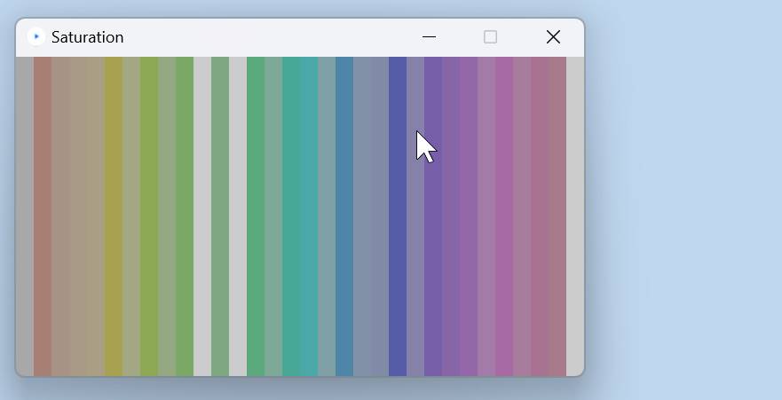
Now let us learn how to work on the canva Working Area (Canvas) sizing, Background color, greyscale, RGB convention. Before that lets have a look on how canva looks. below here is an image which shows and describe what and what are the features of canva.Here i have made a simple grey color, 500px by 500px square canvas >> size(xSize, ySize), background(number)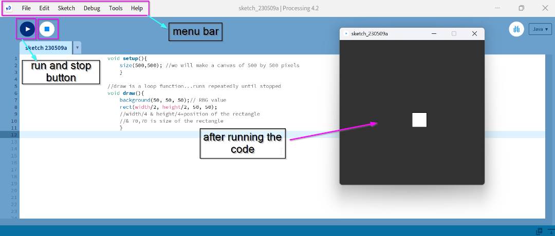
  int posX = 250;

  void setup() {
    size(500,500); //500px by 500px canvas
  }

  void draw() {
    background(51,51,51); //RBG grey value

    //draw line
    stroke(255);
    strokeWeight(2);


    //draw cube
    noStroke();
    fill(255);
    rectMode(CENTER);
    rect(posX,250, 50,50);
  }

  void keyPressed(){
    if (key == CODED){
      if (keyCode == RIGHT){
        posX = posX + 5;
      } else if (keyCode == LEFT) {
        posX = posX - 5;
      }
    }
  }
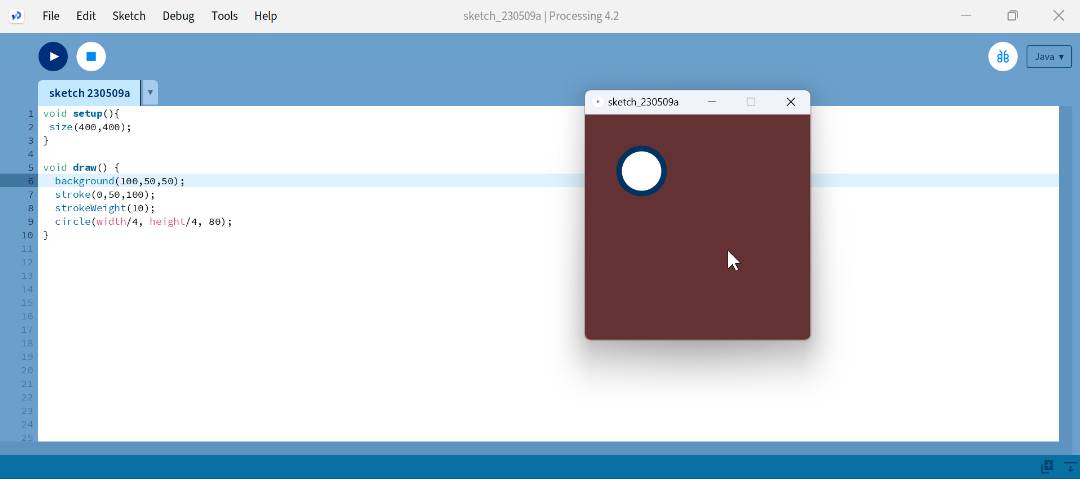
• I tried referring Rico's code and past students code and played with the processing software.below here are the code for different shapes and even tried text.I got the code from last year student kencho but changed the numbers in mine and the shapes.
you can visit his website Here.
  void setup(){
   size(400,400);
  }

  void draw() {
    background(100,50,50);
    stroke(0,50,100);
    strokeWeight(10);
    circle(width/4, height/4, 80);
  }
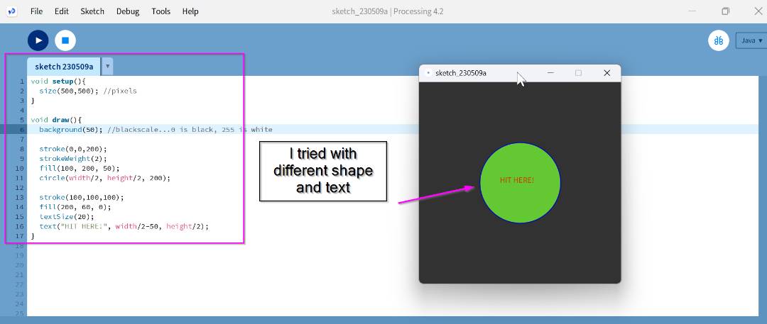
• Below here is the code for the circle and text inside.
    void setup(){
      size(500,500); //pixels
    }

    void draw(){
      background(50); //blackscale...0 is black, 255 is white

      stroke(0,0,200);
      strokeWeight(2);
      fill(100, 200, 50);
      circle(width/2, height/2, 200);

      stroke(50,50,50);
      fill(200, 60, 0);
      textSize(20);
      text("HIT HERE!", width/2-50, height/2);
    }
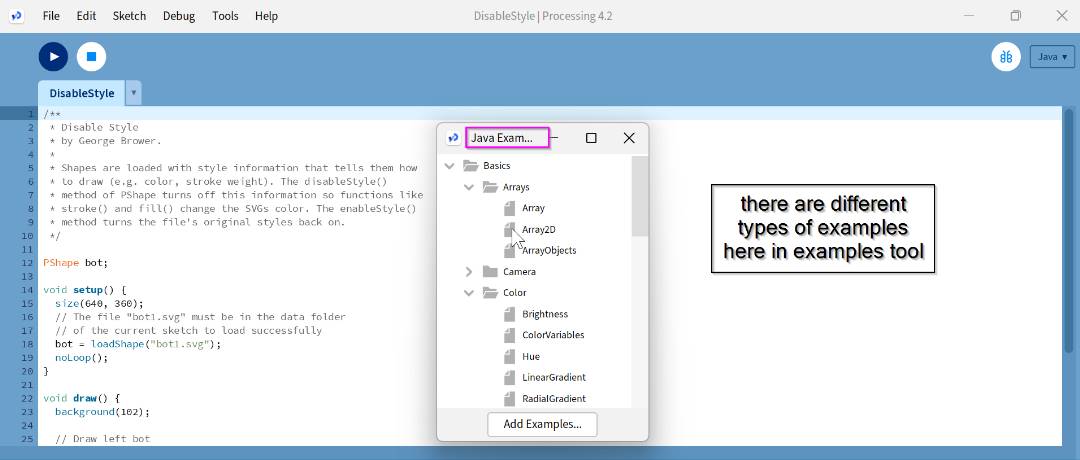
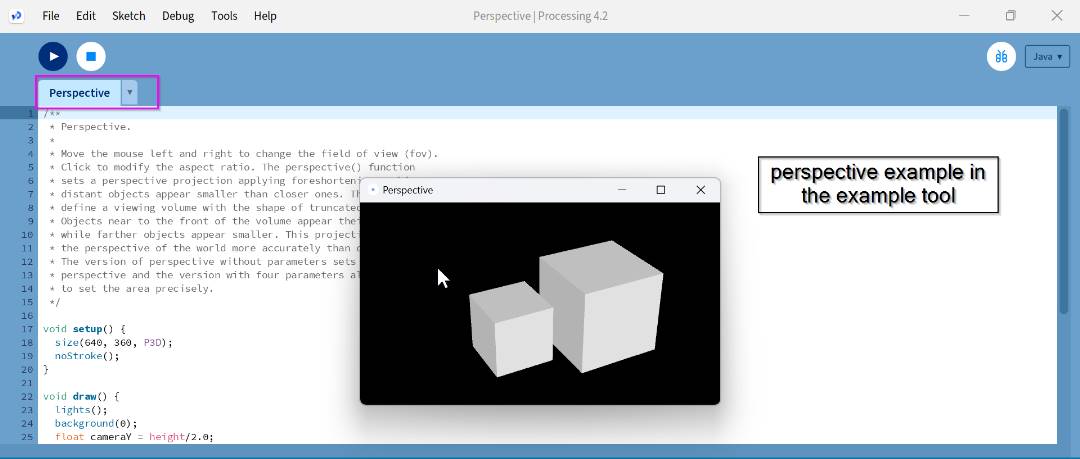
• There are different types of code examples in the tool if you check out.
Sending data from arduino to processing
• So for sending data we need a board, mine is attiny1614 which i used in my output week. I even used FTDI cable and the programmer.
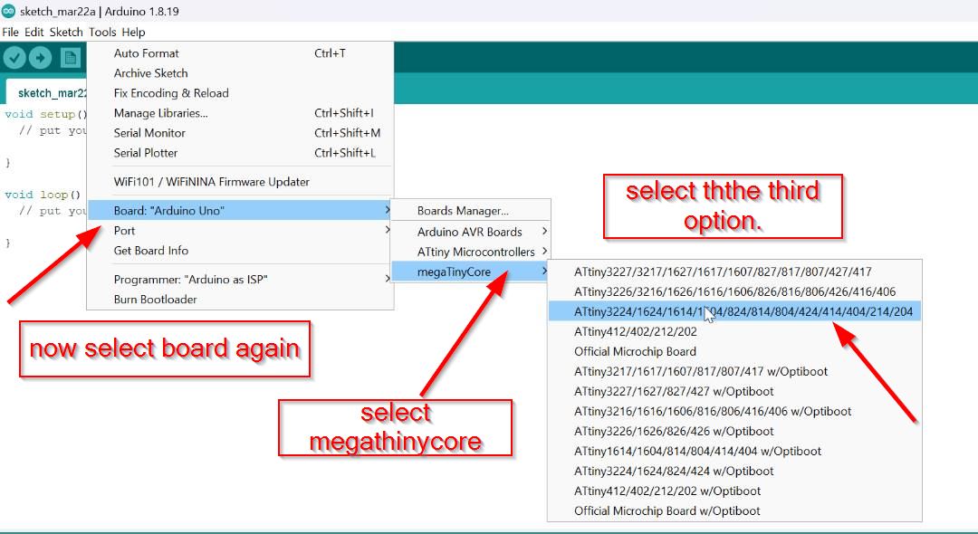
•Setting up your board on arduino below here are the steps to do that.
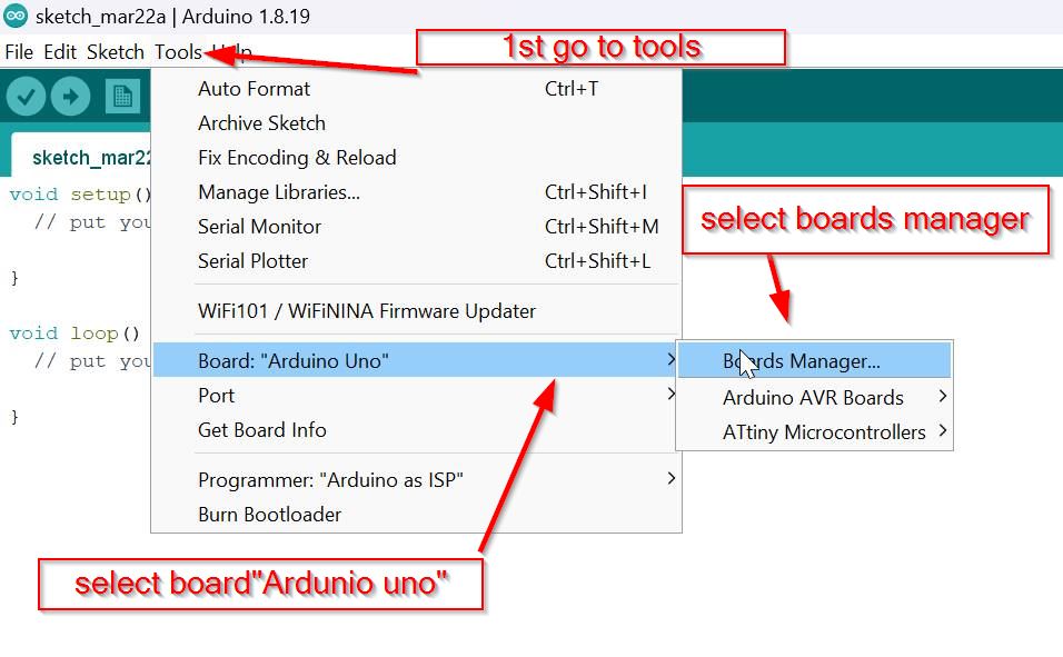
- Now let us set up on arduino ide for the programming.
- Then Go to tools and select the board manager there.
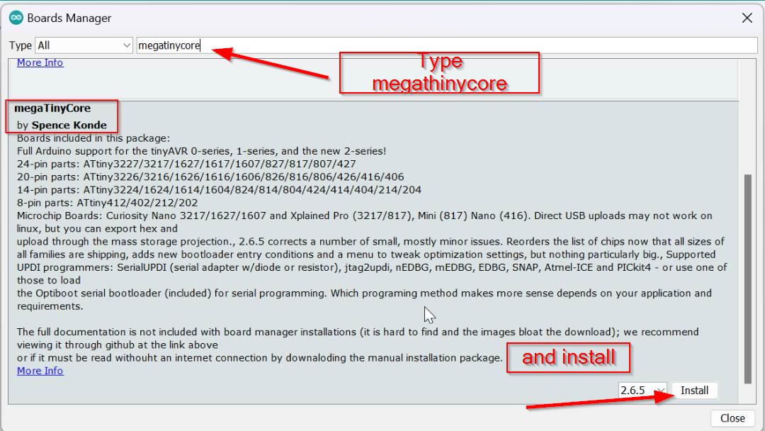
- after that go to the library and search megaTiny core.
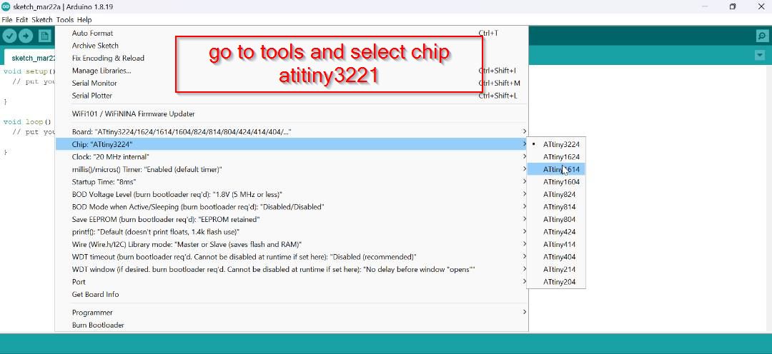
After that select the board to Attiny 1614.
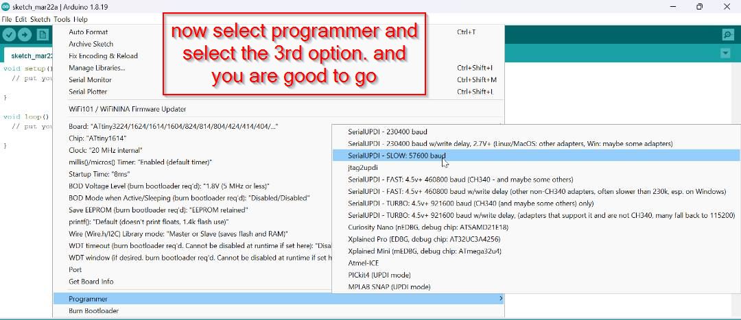
Then select the programmer as shown below and don't forget to select the port .
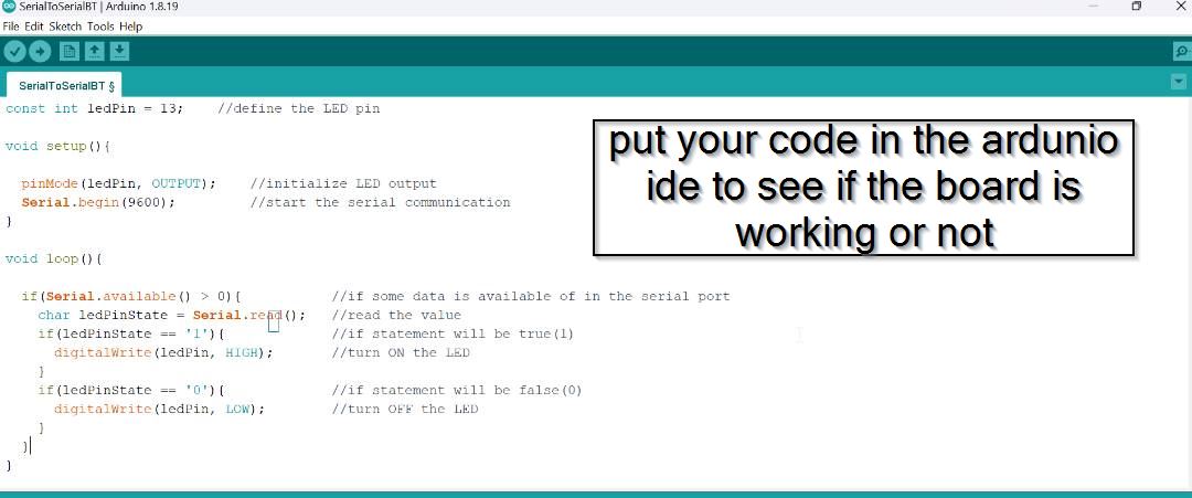
Below here is the code you need to add in your ardunio ide.
  const int ledPin = 13;    //define the LED pin

  void setup(){

    pinMode(ledPin, OUTPUT);    //initialize LED output
    Serial.begin(9600);         //start the serial communication
  }

  void loop(){

    if(Serial.available() > 0){           //if some data is available of in the serial port
      char ledPinState = Serial.read();   //read the value
      if(ledPinState == '1'){             //if statement will be true(1)
        digitalWrite(ledPin, HIGH);       //turn ON the LED
      }
      if(ledPinState == '0'){             //if statement will be false(0)
        digitalWrite(ledPin, LOW);        //turn OFF the LED
      }
    }
  }
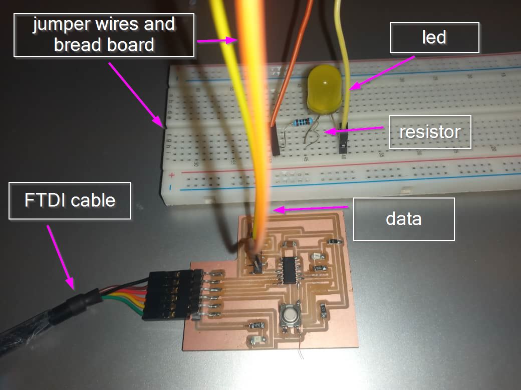
• After you have put your code compile it and then connections on your board.
Connect the100 Ohms resistor to the led long leg(+Ve)
connect Resistor other leg to the data pin of your board
connect led short leg to the GND of your board
• Now let us import the library for serial communication for that follow the steps as follows
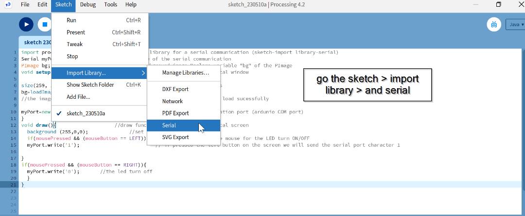
Below here is the code you need to add on the processing software.
    import processing.serial.*;    //import the library for a serial communication (sketch-import library-serial)
    Serial myPort;                 //define name of the serial communication
    PImage bg;                     //add the background image.Declare variable "bg" of the PImage
    void setup(){                  //we will set a resolution for graphical window

    size(259, 194);                //set the image size 259 by 194 pizels
    bg=loadImage ("redLED.png");   //upload the image into the program
    //the image file must be in the data folder of the current sketch to load sucessfully

    myPort=new Serial(this, "com11",9600); //is the name of our communication port (ardunio COM port)
    }
    void draw(){                    //draw function - here is the graphical screen
      background (bg);              //set the background image
      if(mousePressed && (mouseButton == LEFT)){   //get the value of the mouse for the LED turn ON/OFF
      myPort.write('1');                          // if pressed the left button on the screen we will send the serial port character 1

    }
    if(mousePressed && (mouseButton == RIGHT)){
      myPort.write('0');       //the led turn off
      }
    }
• Now run on processing to see the final results.The successful working of the led turning on when I left click the mouse and turning ON and when i right click on the mouse the LED is OFF;