Susana Passinhas @Fab Academy 2023
18. Project development
Prototyping
My approach was to start the project by prototyping it using the Barduino board, which has an ESP32 (the microcontroller I am going to use) to innerstand the circuit and test the code.
Materials to test the input
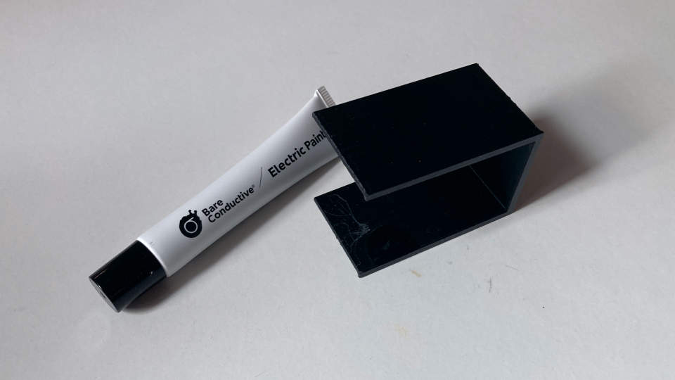
I started by testing the input part of my final project - the energetic hybrid pod. It has a 3D printed capsule (PLA) that acts as the input - capacitive sensing. So I wanted to test using conductive ink below a 3D printed structure to see if I could still read the signals. I used a little piece I had 3D printed before in PLA and black conductive ink from Bare Conductive.
Quickly testing if the conductive ink in a PLA 3D printed surface works using my input week code with SAMD11
To run a quick test I used the code I have done for my input device week using this time the conductive ink in the 3D printed object connected with a wire to a pin in the SAMD11 (because in my PCB I use a SAMD 11).
I quickly innerstood it worked and I could measure the values coming out of the input.
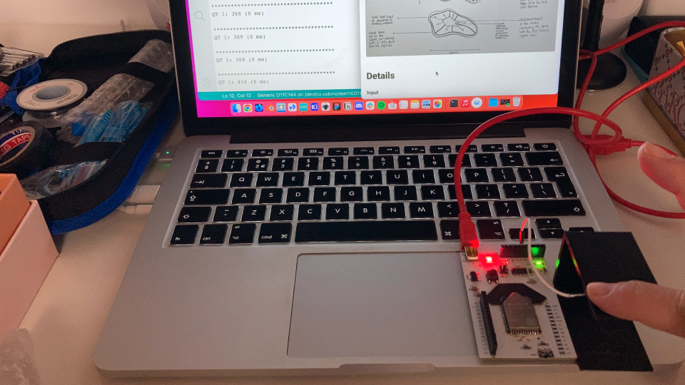
Testing the conductive ink in a PLA 3D printed surface, but now with the ESP32
So now that I knew the conductive ink was going to work for my input, it was time to use the ESP32 microcontroller instead of the SAMD 11. The ESP32 has touch pins and more memory than the SAMD11, it also supports wifi and in general has much more potential than the SAMD11 to be used in my final project.
The first thing I realized is that I couldn't use the same library I was using for SAMD11 (adafruit)... So I started to search for tutorials, I tried with this one and this one and I was struggling to make it work...but then I saw a video that was simply using the capacitive sensor/touch library of the ESP32!
It was really simple, I just went to the examples → ESP32 → Touch → Touch Read, I simply had to use a touch pin from the ESP32 to connect my capacitive sensor and that was it! I used the PIN GPIO14 which is the Touch6 pin.
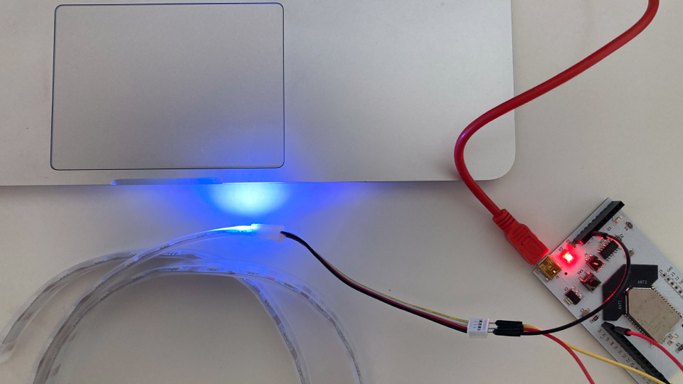
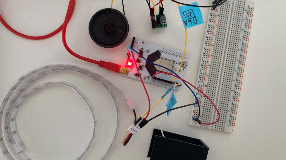
Testing the neopixels string in the ESP32
So after I had my input working it was time to test my output (one of them, to start with) - the neopixel strip LEDs. I started by connecting the neopixel strip to the board. The neopixel strip has a GND (black), 5v (RED), DATA IN (yellow) and the DATA OUT(white). I used the DATA IN so I can send the code to the neopixel strip.
This time I quickly innerstood there was a library I could use for the neopixel strip. I actually installed it in the Arduino IDE itself, by searching the library and installing it (using the menu "manage libraries"). Once it was installed I went to the examples → AdaFruit NeoPixel → Simple. It was working perfectly, I simply needed to change how many LEDs I wanted to light up in the NUMPIXELS variable and the PIN for the DATA (13).
Testing the input with a single color output in the ESP32
Now that the input and output were working properly using the ESP32 it was time to make them work together! So my first goal was to make the neopixel strip light up once the input changes values (a hand is close to or touching the object).
I simply started by joining both codes in the setup() and loop() functions and used an IF condition to the one controlling the neopixel strip lights on or off by relating that to the values being read by the input. The capacitive sensor is always doing readings around the values of 90, but if a hand is close or touching it goes below those values. Now the next step is to divide those values into 7 ranges and map those to the different colors!
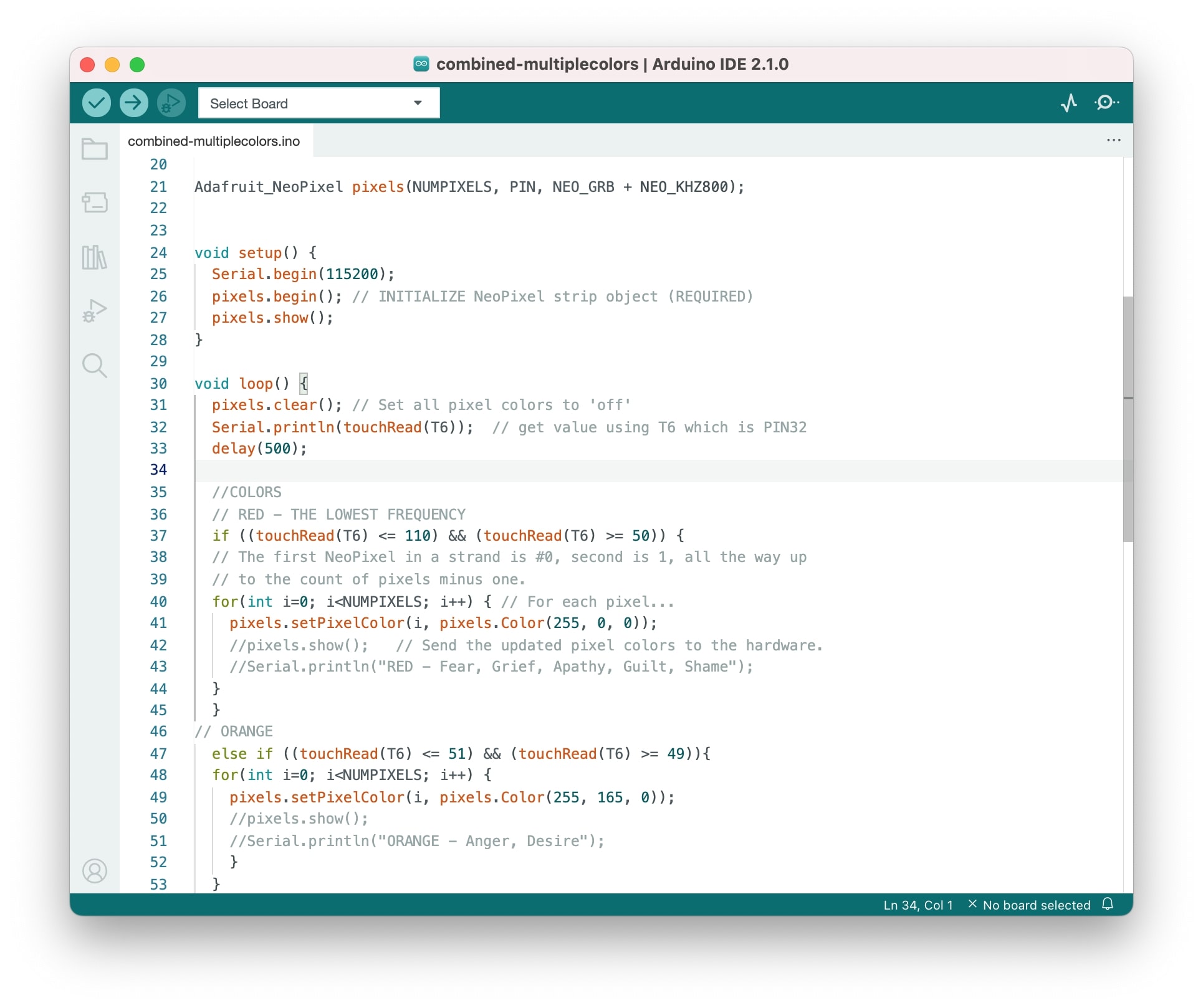
Testing the input with multiple colors outputs in the ESP32
Once I got it working now it was time to explore mapping different colors to the different data of the touch sensor. I used IF conditions and mapped out the value range I was getting into 7 colors: red, orange, yellow, green, cyan, blue, and purple. It would be nice to set up always a minimum value and maximum and divide that by the number of colors...but now that I have seen the result of the colors changing it might not be as perfect as I thought because it might be that it will be changing colors all the time and instead of being pleasant to interact with could be really overwhelming...so, for now, I am sticking to fixed values mapped to a specific color.
The struggle I found is that the colors do this flickering that I believe it's related to the delay, so the flickering seems to be when the delay time has passed and the flickering is the time it takes to check the current value and shows it... I tried with no delay and the flickering is much more intense... So my next step was to investigate this problem...
Solving the flickering...
It was actually pretty simple! I was asking the code to show the color of the values in every IF condition instead of just asking the code to show the led color at the end! Problem solved and my cat even tested it!
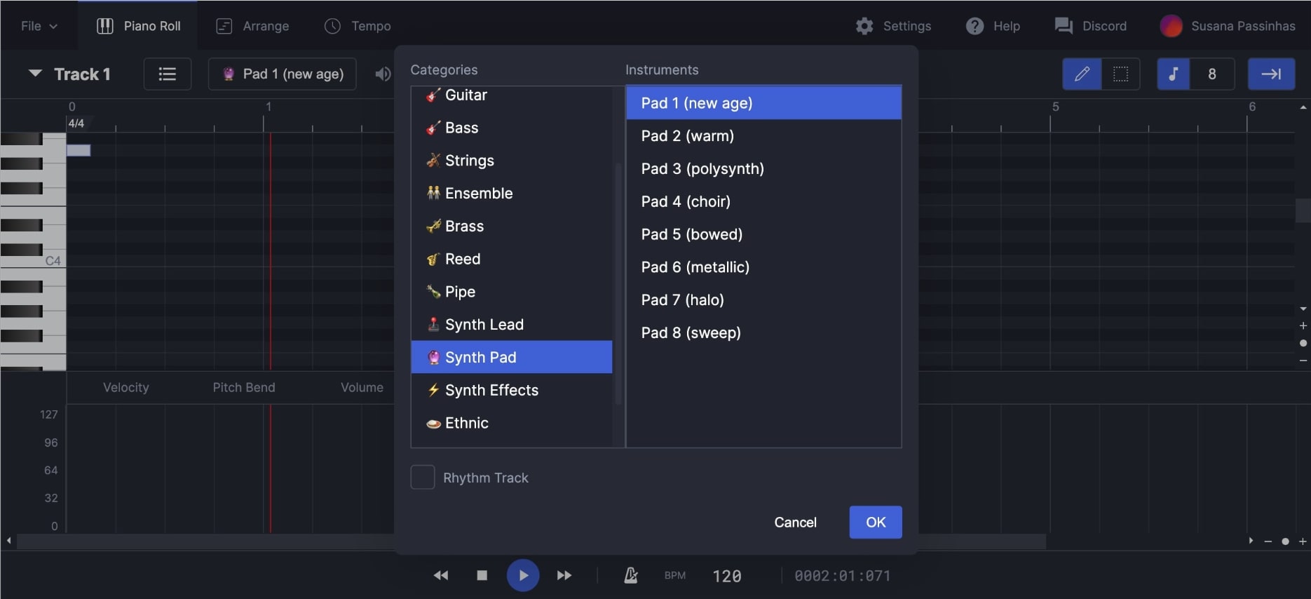
Starting with the sound
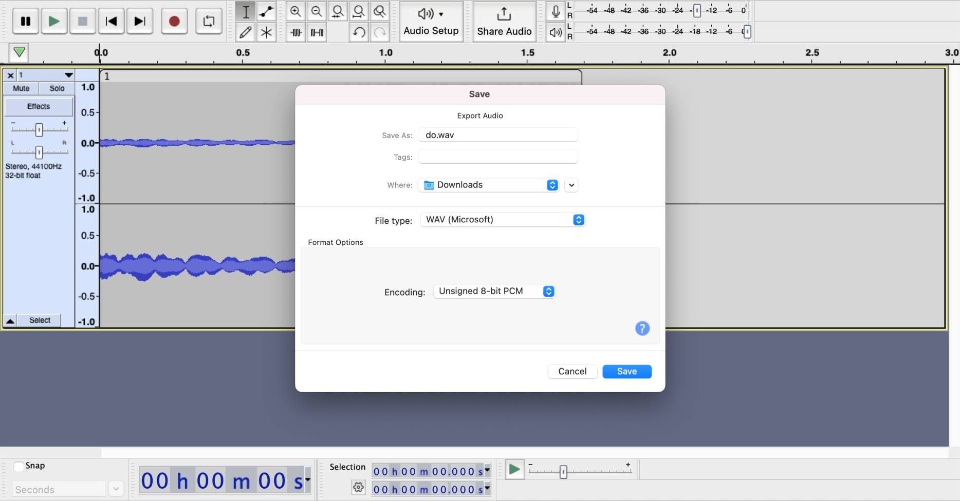
I was now ready to explore the sound output, but first I needed audio samples. I search for audio software online I could use to create musical notes. I found an online open-source midi editor that was really easy to use and had cool sound effects, the signal.vercel.app. I choose the sound effect I liked the most from the categories → Synth Pad → Pad 1 (new age). Then I just played the musical scale one by one and exported it in WAV (only allows to export in WAV). To use the code that allows to play sounds from the ESP32 we need to convert the wav into h (C), so I downloaded Audacity, an open-source sound editor, and saved the wav files in wav again but with the encoding "Unsigned 8-bit PCM" so that the ESP32 could innerstand it.
Econding the sound
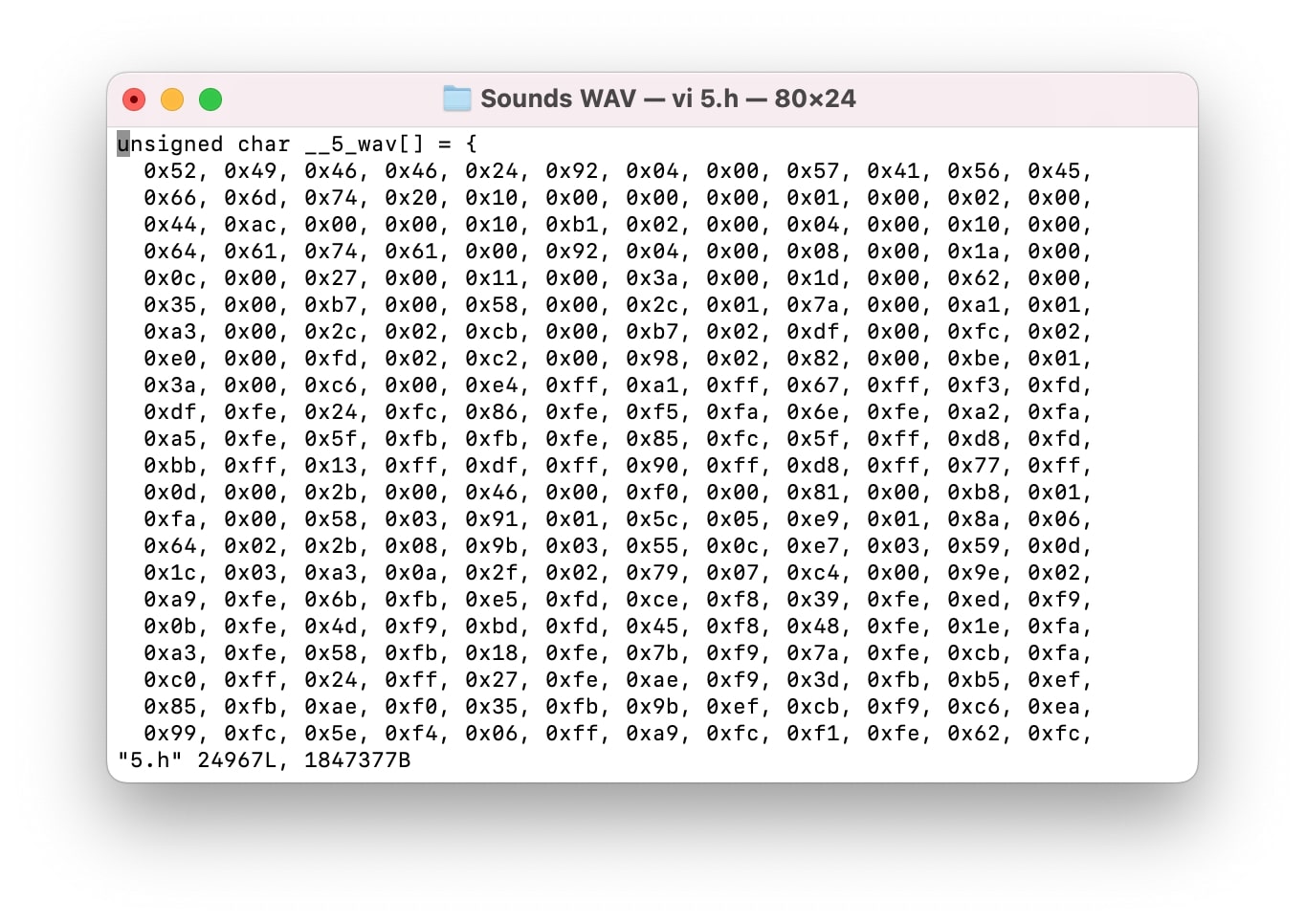
To be able for the ESP32 to play wav files we need to encode it to C language, converting the wav into h files. It is quite simple to do that by using the terminal. After making sure we are in the correct folder we can simply type "xxd -i nameofthesong.wav > nameofthesong.h" and it will generate the file in the same folder.
|
xxd -i nameofthesong.wav > nameofthesong.h
|
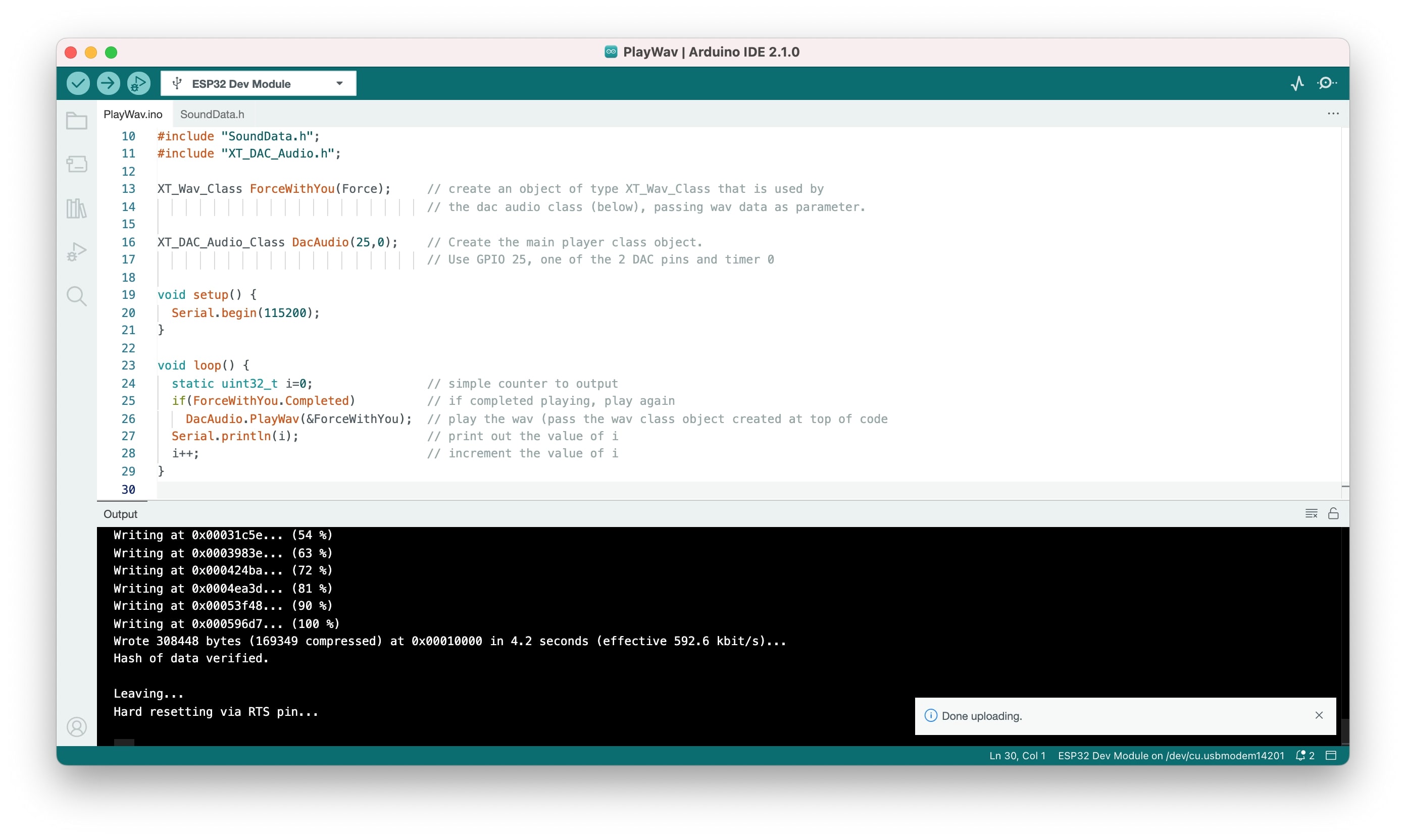
Testing sound as an output
To use sound in the ESP32 I followed this tutorial and used the XT_DAC_Audio Library by XTronical. I also used the PAM8302 amplifier to make sure the volume wouldn't be too low.
The code is quite simple and uses the functions of the library, it basically says that if the sound is not playing, then play it. The trick here is to have another file that has the c code for the wav and call it in a variable. It worlek nicely, even though the sound quality was not super clean.
Integrating everything doesn't work as well as expected...
I was quite happy to get everything integrated and really thought it would be super simple, my idea was to have a musical note being played when the IF condition of each color was TRUE. So I did all the different files and soon realized it was not working as expected...
The speaker seems to be getting an interference and I can't quite innerstand why. It could be the wiring. It seems the voltage might be getting in the speaker, maybe bad soldering...but it could also be that the speaker will not work as I envisioned in the beginning. I read somewhere when I was super absolved trying to figure out (yes I spent 12h straight trying different things and innerstanding what was happening) that the ESP32 Touch pin could be too sensitive, meaning it could be sending some signals to the PIN of the speaker...I even change the Touch pin and solder it to the other side of the board, but still, I had the same problem. I spend too much time on it and decide to move on and back to it later on.
I decided to leave the audio for later and move on to manufacture my PCB. After the initial tests and prototype it's now clear what I need in my PCB (including the possibility to connect audio later on).
2D Design
Pod's sketches
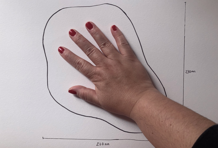
I started by using my own hand to have a sense of the size of the energetic hybrid pod. I also wanted it to be organic, so I just draw with a pen the shape around my hand and used that as a base for the shape of the energetic hybrid pod.
It should roughly be around 220mm x 230mm and in terms of height around 100mm.
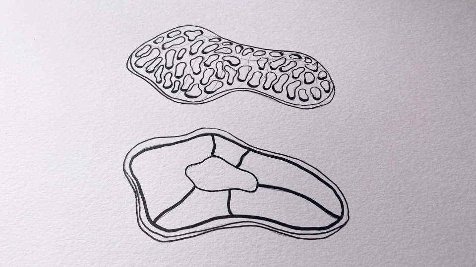
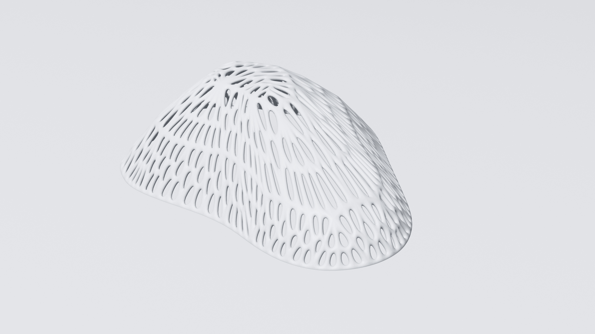
For the capsule (top), I envision it to be irregular and sort of ergonomic fitting more or less the curvature of a human hand. Inspired by some experiments I did in the 3D scanning and printing week (check at the bottom of the page the vase and lamp) and also my mood board I really wanted to achieve this futuristic look that also feels quite natural and organic, almost like a coral reef structure. The capsule is 3D printed and modeled in Blender.
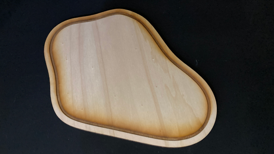
The base is in wood, flat, and just with a little raster where the capsule sits and the conductive ink can be connected to reach the PCB that will be in the center of the base.
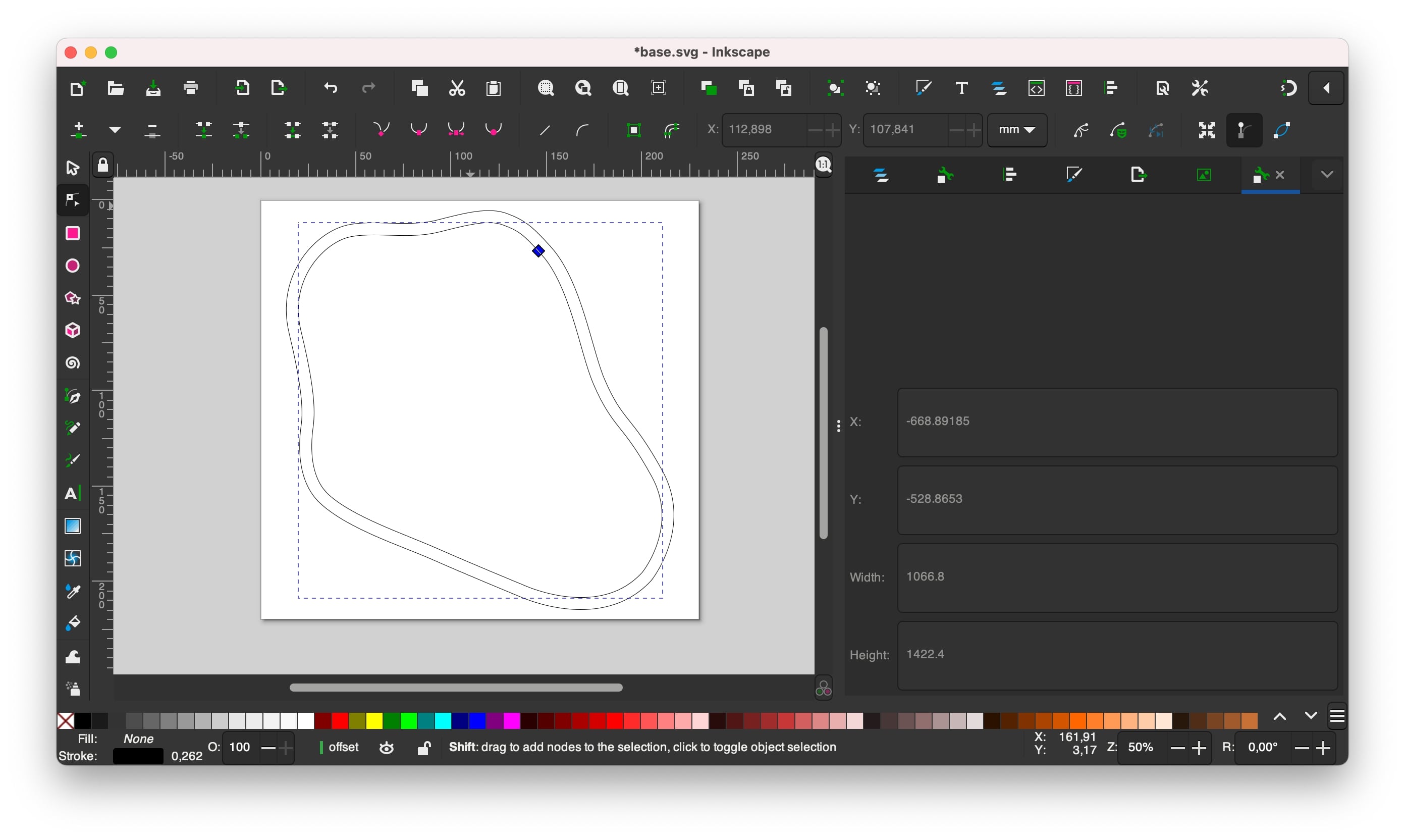
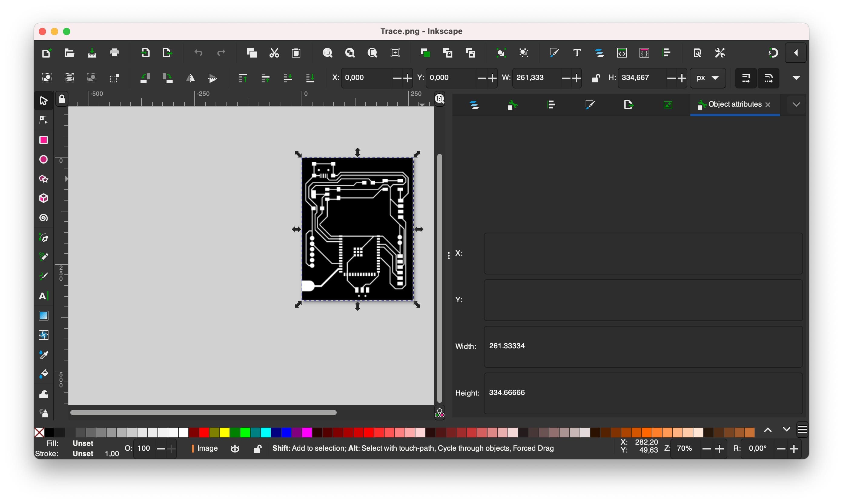
2D Design in Inkscape - pod's base
I started by adding the dimensions to a new file 220mmx230mm. Then I imported a photo with the shape I had drawn before. I used the pen tool to design the shape and then I needed to do the inner offset. I check this tutorial to see how to apply the offset, it was quite easy. I went to path → dynamic offset and then just move it to the point I wanted. Then I exported it as a .dxf file.
2D Manufacturing
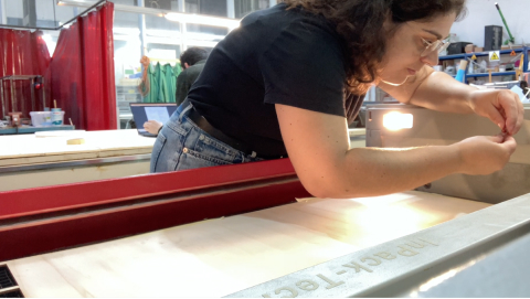
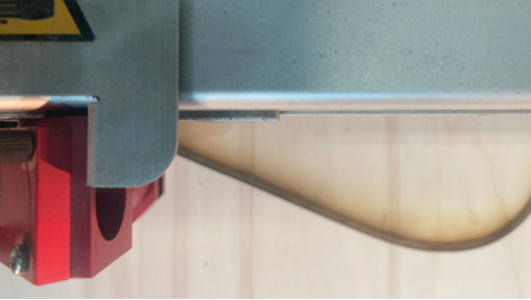
Subtractive manufacturing - laser cutting
To do the subtractive manufacturing I used the Trotec Speedy 400 we have at the lab. I started by opening the DXF file in Rhino. Then used the command "Print" and add the correct colors to the lines. The Blue line was to engrave the wood so that the capsule could fit there and the red line was to cut the material completely. I used the following parameters for the plywood 4mm.
Wood
- Engrave: Power(40.00), Speed(5.00), PPI/Hz(1000)
- Cut: Power(75.00), Speed(0.50), PPI/Hz(1000)
|
3D Design - Capsule
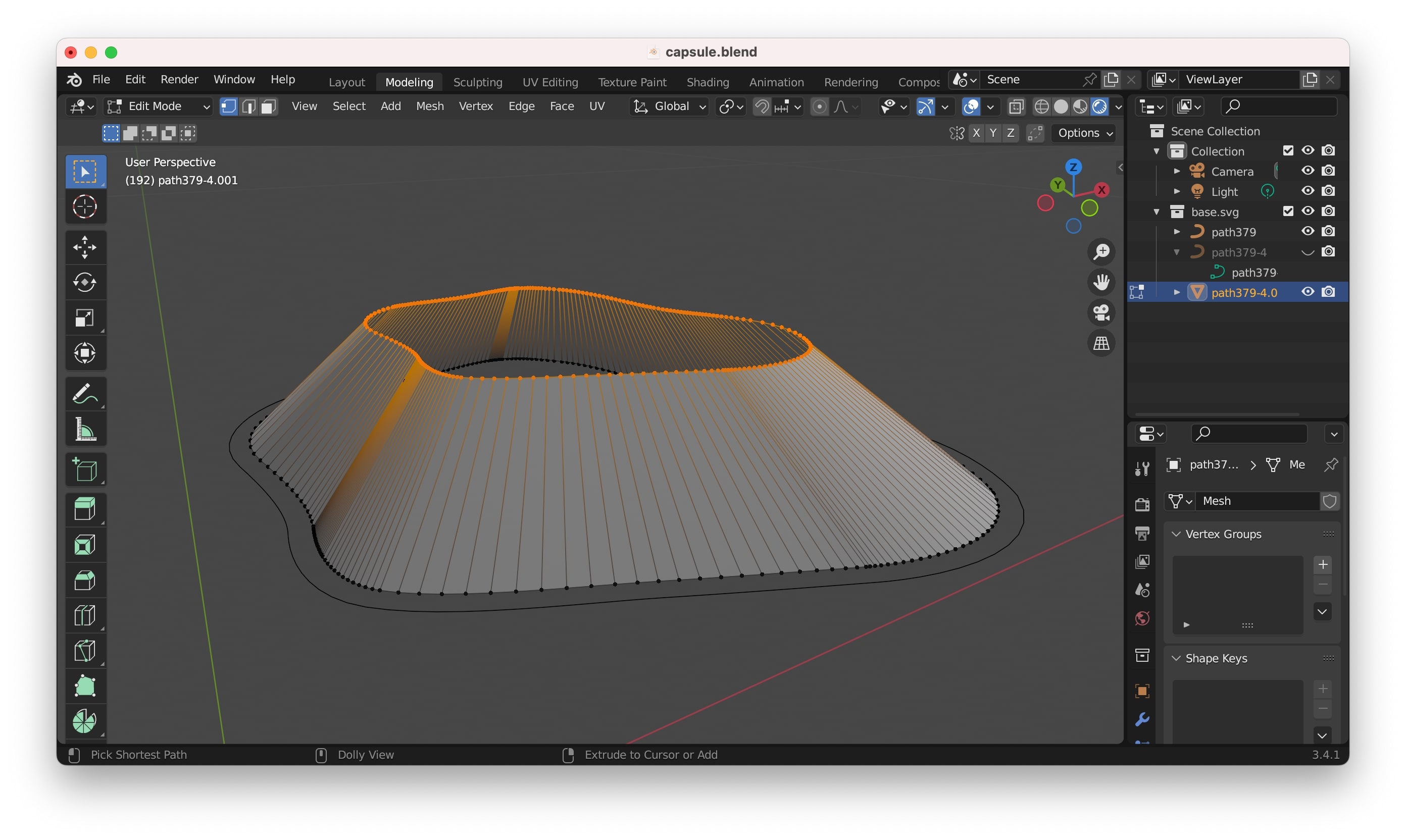
3D Modeling in Blender - from svg to the skeleton mesh
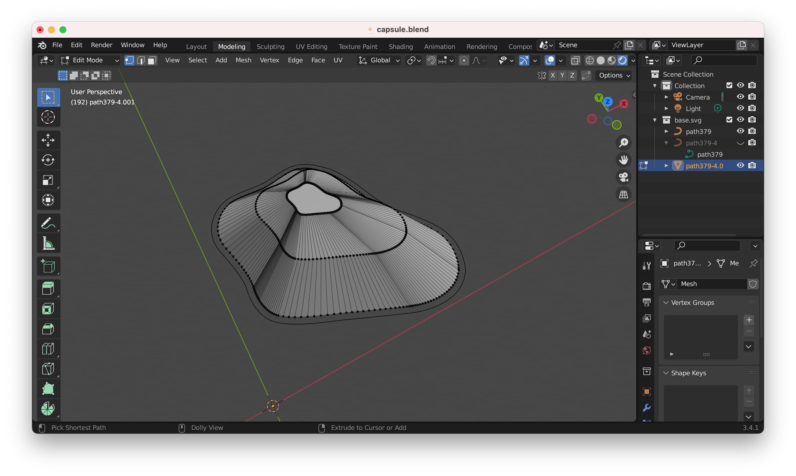
To model my capsule in 3D I used Blender. I started by importing the svg of the base shape I created in Inkscape. In order to be able to extrude it I needed to convert the svg into a mesh, this can be done by right-clicking on the svg and then selecting → convert to → mesh.
After then it's easy to extrude the mesh. I extrude it vertically (z-axis) by using the key "E" while selecting the mesh in "edit mode". I also scale it to be smaller than the base to that it is closer to the final shape I wanted to achieve. Then when I was ready I just closed the shape, still with the vertices selected in edit mode, and pressed the key "F", to create a face with those vertices.
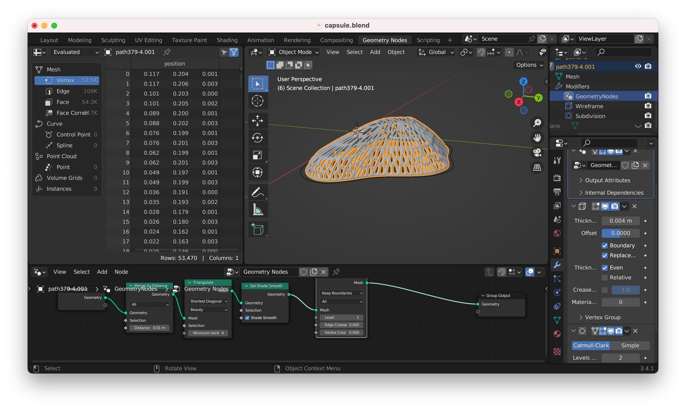
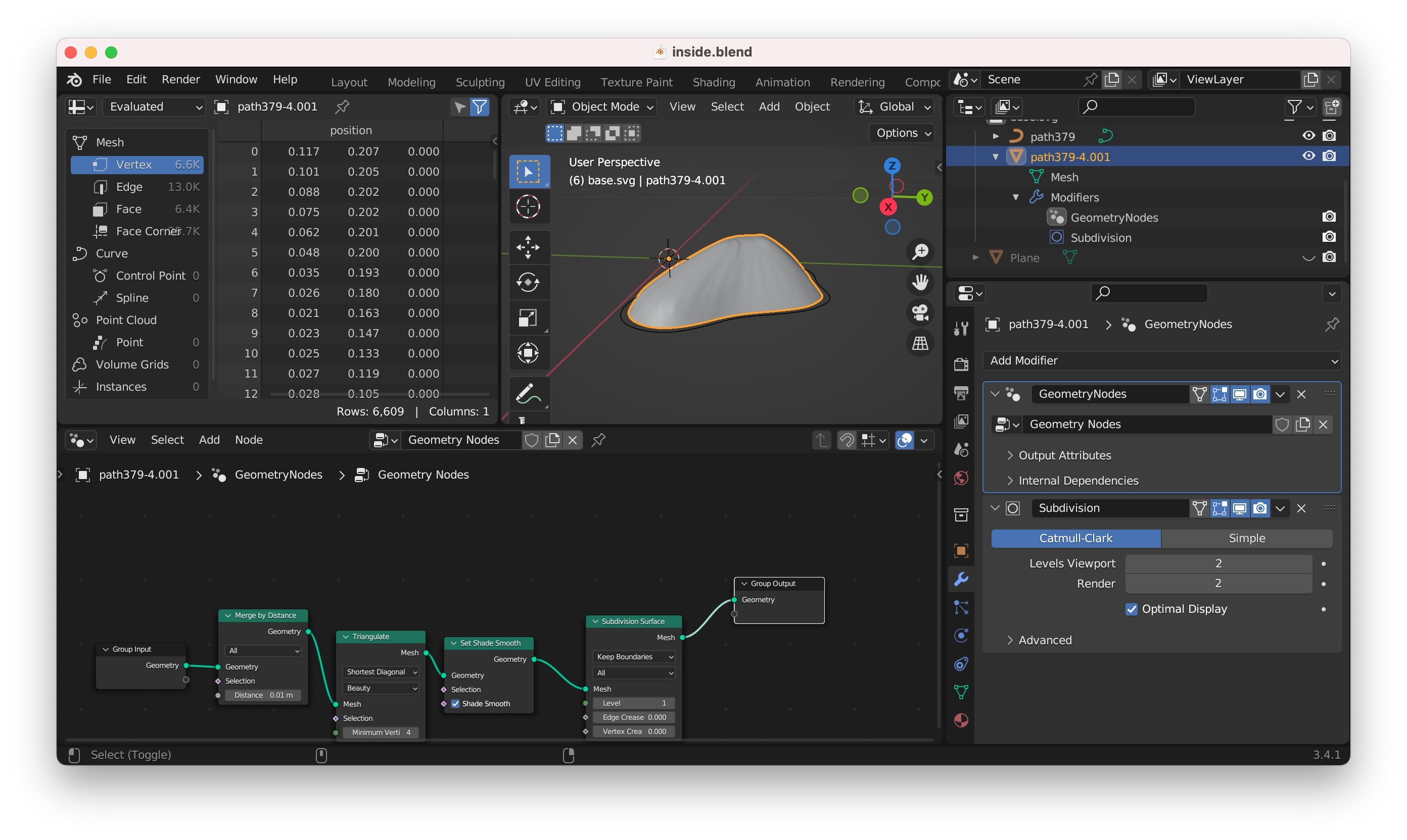
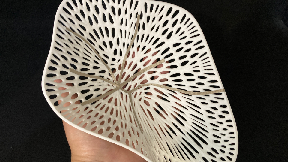
3D Modeling in Blender - making the mesh organic with geometry nodes
To create the organic effect I was after I followed a tutorial that I followed before. I went to the geometry nodes tab and created a new one. Then I added the node "Merge by Distance", followed by the node "Triangulate", the "Set Shade Smooth" and the "Subdivision Surface".
Then I went to the modifier and added the "Wireframe" and the "Subdivision Surface".
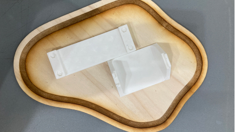
3D Manufacturing - Capsule
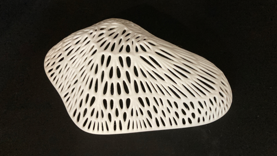
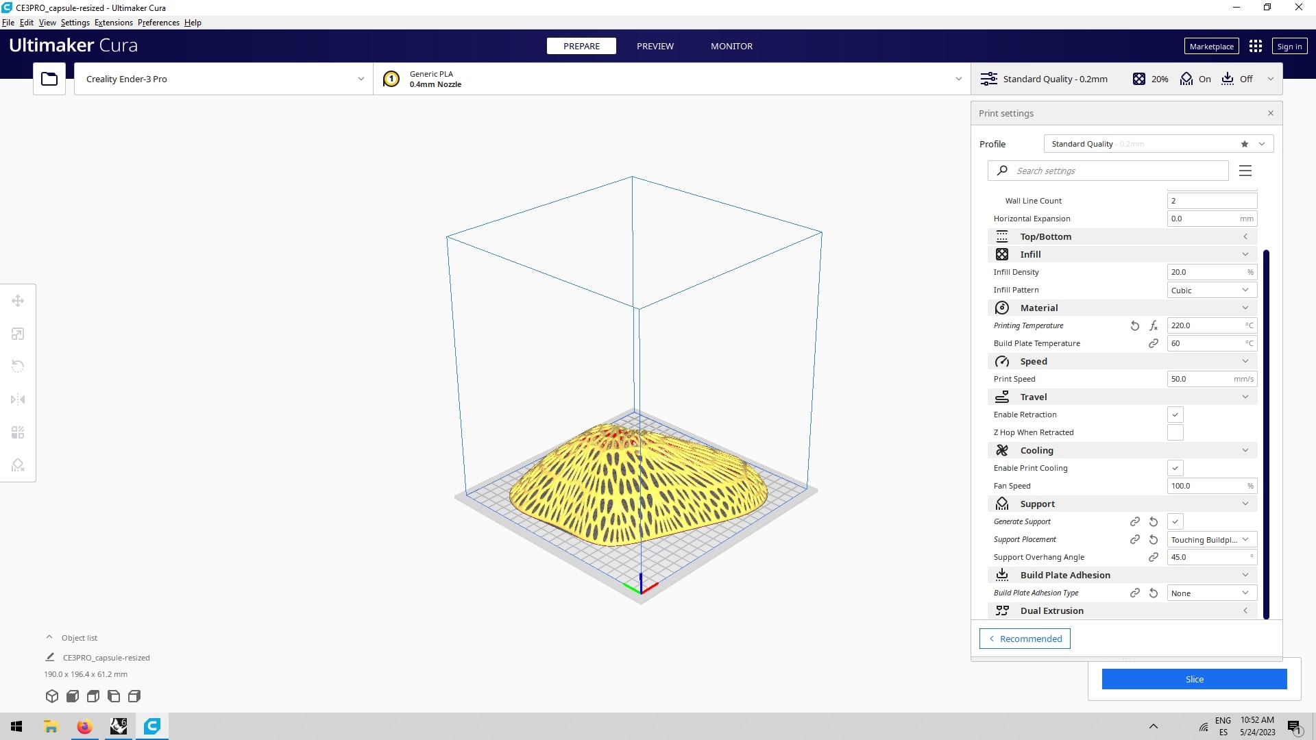
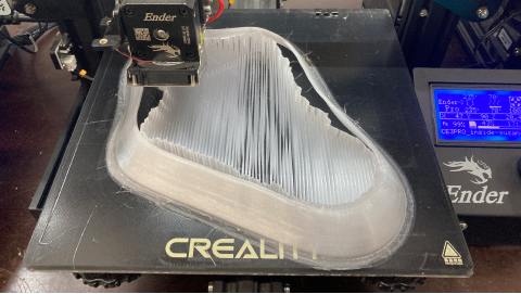
Additive manufacturing - 3D printing the capsule
I used the Ender 3 Pro we have at the lab to start manufacturing the capsule. For the capsule I used white PLA. I used the following parameters:
- Quality: standard 0,2mm (the distance/pressure between slices)
- Material:PLA (a type of plastic)
- Temperature: 215°(the temperature that PLA melts the best)
- Plate temperature 60°(the temperature of the bed so that the material holds to it)
- Infill: 20% (the density of the interior net)
- Speed: 50ms (how fast the nozel moves)
- Plate adhesion: skirt (the type of base for my object)
- Support: Tree (the type of support that helps the object not to fall)
|
3D Manufacturing - Inner Capsule
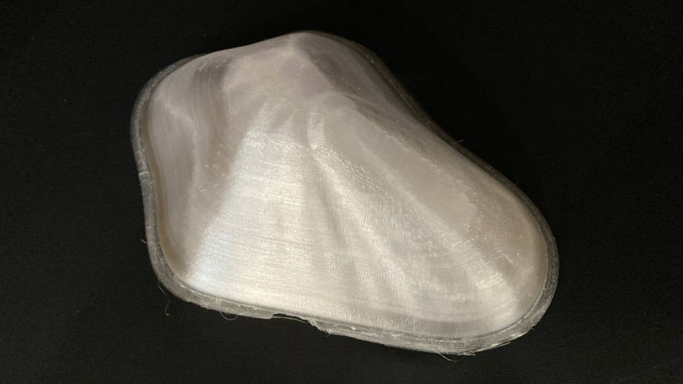
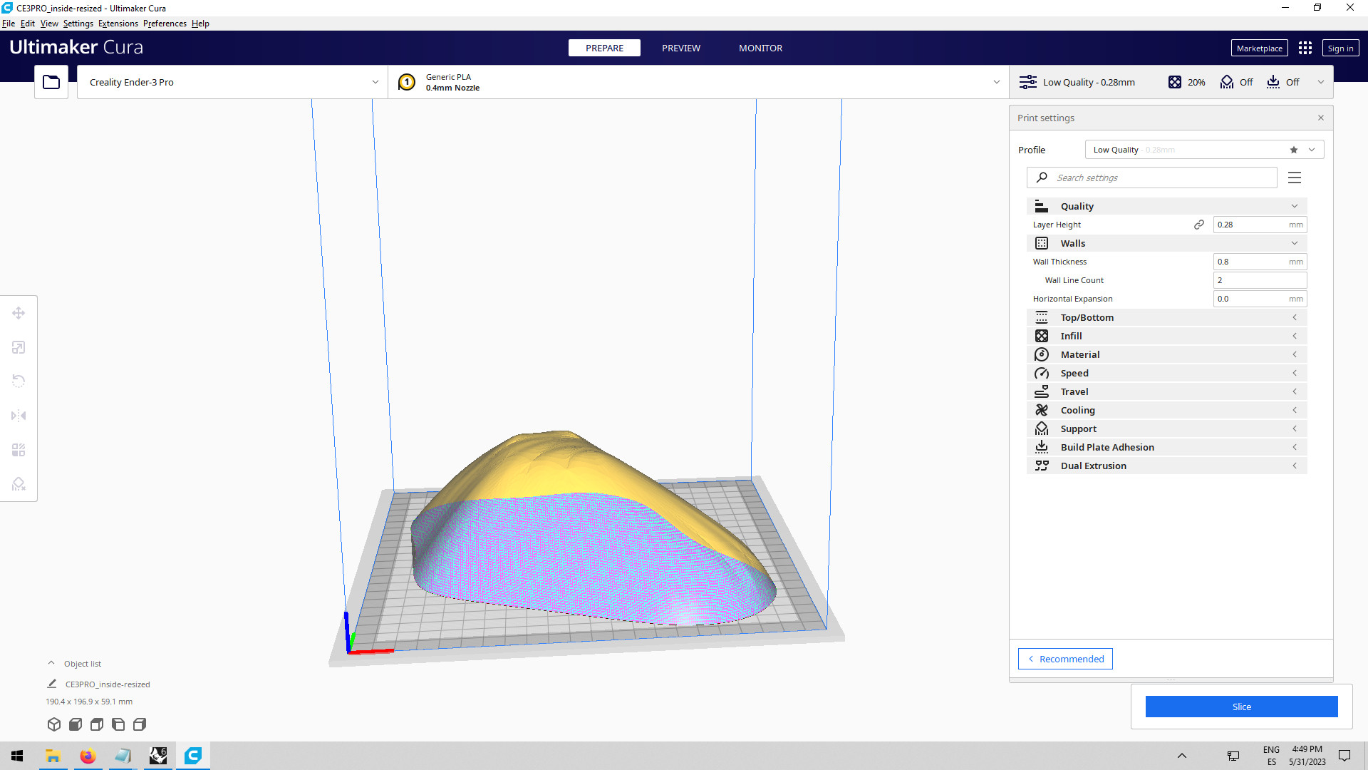
Additive manufacturing - 3D printing the inner capsule
I used the Ender 3 Pro we have at the lab to start manufacturing the inner capsule. For the inner capsule I used clear PolyLite PETG. I used the following parameters:
- Quality: standard 0,2mm (the distance/pressure between slices)
- Material: PolyLite PETG (a type of plastic)
- Temperature: 230°(the temperature that PLA melts the best)
- Plate temperature 70°(the temperature of the bed so that the material holds to it)
- Infill: 10% (the density of the interior net)
- Speed: 50ms (how fast the nozel moves)
- Plate adhesion: skirt (the type of base for my object)
- Support: Tree (the type of support that helps the object not to fall)
|
Electronics
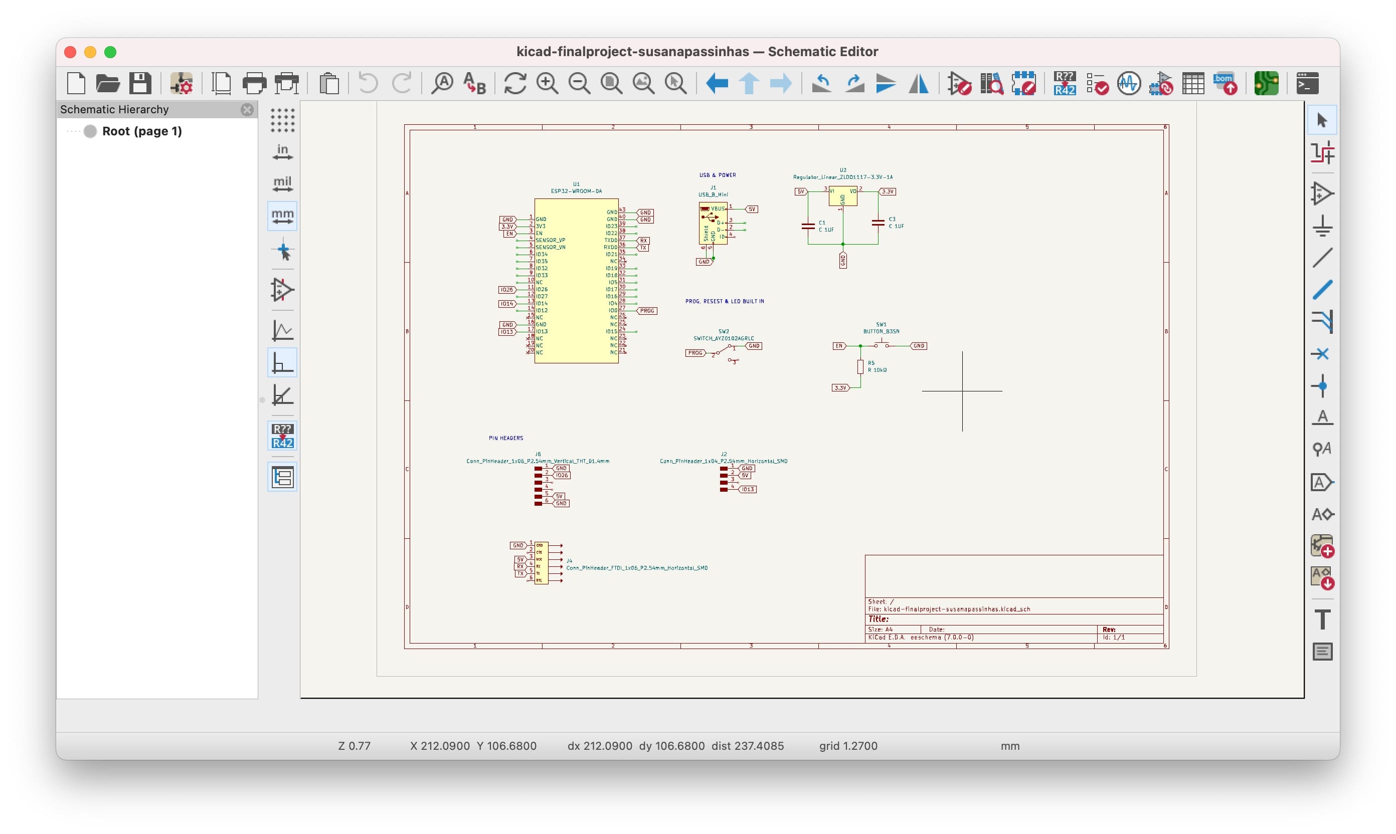
Designing the circuit in Kicad
I started designing my circuit in KiCad knwowing wich components I needed to use (because I have done the prototype before):
- 1x ESP32 Waroom DA
- 1x USB Mini
- 1x Button
- 6x Pin Heads Female
- 10x Pin Heads Male
- 1x Voltage Regulator 5v
- 2x Capacitor for 5v
- 1x Resistor 10kΩ
- 1x Switch
|
So after I put them all in the schematic editor I started to label them so that it would be easier to connect them in the PCB Editor. I only used labels for the PINs I was going to use: GPIO 14 (T6) for the capacitive sensor, the GND, 3.3v and 5v to power and ground the circuit (Neopixels uses 5v), RX and TX to program the board (I used a FTDI cable), the pin GPIO 18 (the label says 13 but I eventually needed to changed it to the 18 so the design of the circuit worked better) for the neopixels data, the GPIO 27 to program the ESP32 Waroom DA and I also left the GPIO 26 DAC to play with sound later if I wanted since I also explored that possibility.
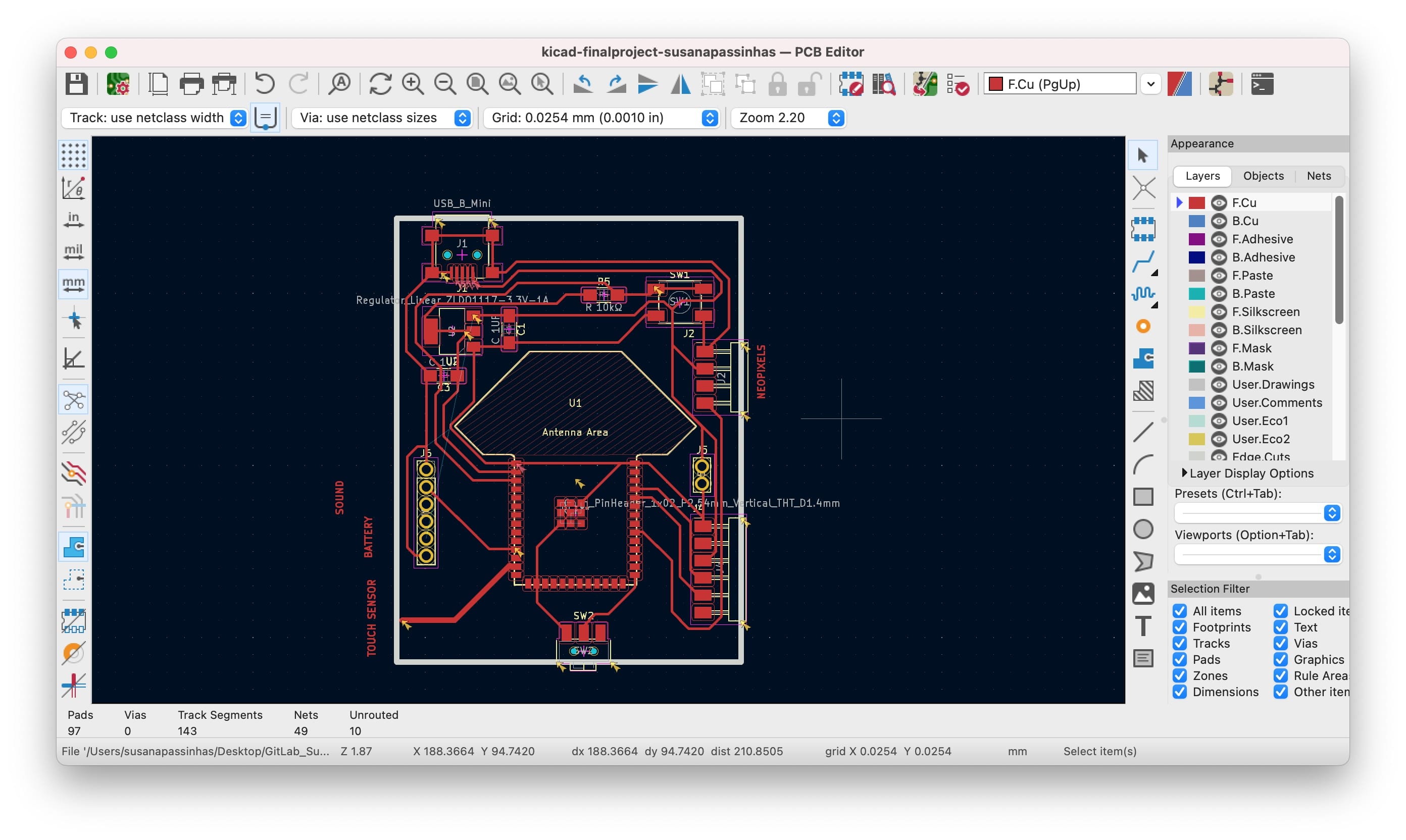
Then I just connected the labels in the PCB editor using a tickeness of 0,4mm (so it would fit the endmill of the machine).
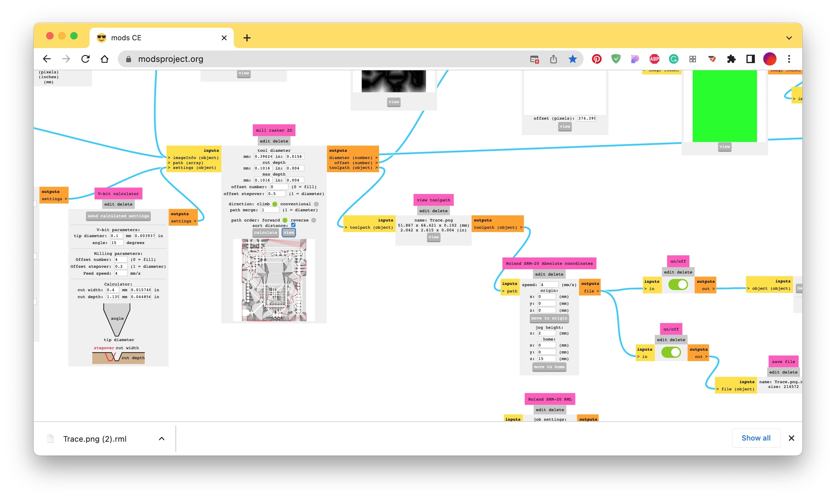
Preparing the files for the machine
After exporting the SVGs from KiCad I opened them in Inkscape and made sure to set the colors correctly. White is the color that stays and black is the color that is what is going to be removed. Before exporting the PNG I made sure to set up the dpi to 1000.
When they were ready I used the MODS to prepare the files for the machine. I selected the PNG, first the trace, where I choose the 1/64 (0,4mm) endmill, I also made sure the coordinates were set to 0 and only the "move to origin" z-axis had a 15mm so it doesn't scratch the PCB. After the traces I did the configuration for the holes and then finally for the cut, using both the 1/32 (0,8mm) endmill. I also set up the offset to 0 so the machine would clean the entire black out of the PCB. I used the SRM20-MILL machine we have at the lab for this.
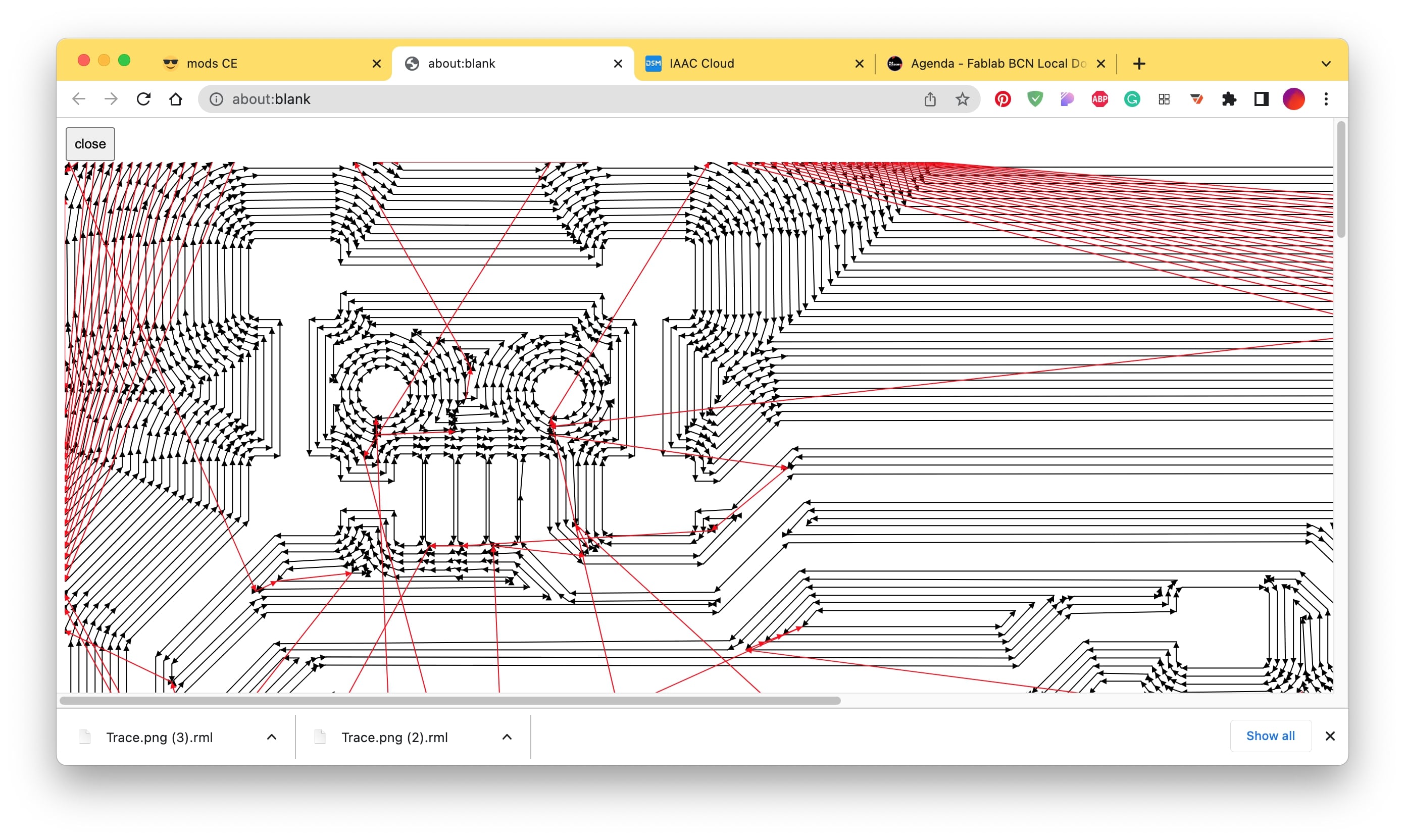
I double-checked the file to see if the paths were also good and ready for the machine by clicking the "view" button.
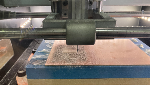
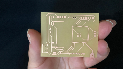
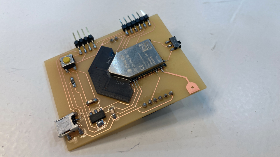
Manufacturing the PCB
So now that I was ready for the machine, I started by preparing the PCB by using double side tape to glue it to the bed of the machine. Then I calibrated the machine first with the endmill 1/64 (0,4mm). I did this by using the controls in the software of the machine and moving first the x and y to the 0 position, then with the z we need to be more careful by putting it close enough but then gently dropping it with our hands so that the endmill doesn't break. Once I set them up I simply used the button "cut" and added the file I wanted, first traces, then holes then outline.
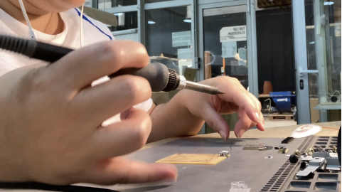
Soldering
I already had my list of components and the PCB, it was time to solder! Soldering went pretty smoothly. I soldered at a temperature of 400 degrees celcius.
The code
Using Touch pin from ESP32 Waroom DA and Neopixels strip
The code was quite simple. For the capacitive sensor values, I used the Touch PIN T6 (GPIO 14) of the ESP32 Waroom DA. Because it's part of the ESP32 I could use the ESP32 library. I used a simple function to get the values "touchRead(T6)". With these values, I could see in the serial monitor the difference when the capacitive sensor was being touched and not touched and that is how I defined the intervals I would be using to map the colors - simply dividing the 7 colors between the range of the maximum and minimum value I was getting.
The neopixels strip alwaso has a library I could work with, so I called that library in the begining of the code, I defined what was the digital PIN the neopixels was going to be connected to and also the number of LEDS I would be using. I initialized the pixels in the setup and then in the loop I was continuously checking the data from the T6 and check using an IF CONDITION if those values belong to a specific color interval, if so the neopixel strip light up the specific color to that interval, at the end to actually see the color we need to add a function that shows the LEDs on "pixels.show();".
// NeoPixel Ring simple sketch (c) 2013 Shae Erisson
// Released inner the GPLv3 license to match the rest of the Adafruit NeoPixel library
#include
#ifdef __AVR__
#include // Required for 16 MHz Adafruit Trinket
#endif
// Which pin on the Arduino is connected to the NeoPixels?
#define PIN 18
// How many NeoPixels are attached to the Arduino?
#define NUMPIXELS 21
// When setting up the NeoPixel library, we tell it how many pixels,
// and which pin to use to send signals. Note that for older NeoPixel
// strips you might need to change the third parameter -- see the
// strandtest example for more information on possible values.
Adafruit_NeoPixel pixels(NUMPIXELS, PIN, NEO_GRB + NEO_KHZ800);
void setup() {
Serial.begin(115200);
pixels.begin(); // INITIALIZE NeoPixel strip object (REQUIRED)
pixels.show();
}
void loop() {
pixels.clear(); // Set all pixel colors to 'off'
Serial.println(touchRead(T6)); // get value using T6 which is PIN32
delay(500);
//COLORS
// RED - THE LOWEST FREQUENCY
if ((touchRead(T6) <= 110) && (touchRead(T6) >= 50)) {
// The first NeoPixel in a strand is #0, second is 1, all the way up
// to the count of pixels minus one.
for(int i=0; i
pixels.setPixelColor(i, pixels.Color(255, 0, 0));
//pixels.show(); // Send the updated pixel colors to the hardware.
//Serial.println("RED - Fear, Grief, Apathy, Guilt, Shame");
}
}
// ORANGE
else if ((touchRead(T6) <= 51) && (touchRead(T6) >= 49)){
for(int i=0; i
pixels.setPixelColor(i, pixels.Color(255, 165, 0));
//pixels.show();
//Serial.println("ORANGE - Anger, Desire");
}
}
// YELLOW
else if ((touchRead(T6) <= 48) && (touchRead(T6) >= 46)){
for(int i=0; i
pixels.setPixelColor(i, pixels.Color(255, 255, 0));
//pixels.show();
//Serial.println("YELLOW - Courage, Pride");
}
}
//GREEN
else if ((touchRead(T6) <= 45) && (touchRead(T6) >= 43)){
for(int i=0; i
pixels.setPixelColor(i, pixels.Color(0, 255, 0));
//pixels.show();
//Serial.println("GREEN - Willingness, Neutrality");
}
}
//CYAN
else if ((touchRead(T6) <= 42) && (touchRead(T6) >= 39)){
for(int i=0; i
pixels.setPixelColor(i, pixels.Color(0, 100, 100));
//pixels.show();
//Serial.println("CYAN - Reason, Acceptance");
}
}
//BLUE
else if ((touchRead(T6) <= 38) && (touchRead(T6) >= 36)){
for(int i=0; i
pixels.setPixelColor(i, pixels.Color(0, 0, 255));
//pixels.show();
//Serial.println("BLUE - Joy, Love");
}
}
//PURPLE
else if ((touchRead(T6) <= 35) && (touchRead(T6) >= 0)){
for(int i=0; i
pixels.setPixelColor(i, pixels.Color(128, 0, 128));
//pixels.show();
//Serial.println("PURPLE - Enlightenment, Peace");
}
}
else if (touchRead(T6) > 111) {
pixels.clear(); // Set all pixel colors to 'off'
//pixels.show(); // Show them 'off'
}
pixels.show();
}
|
Programming
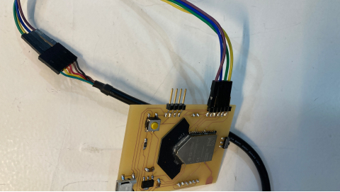
Using a FTDI cable
To program the ESP32 Waroom DA I used an FTDI cable, it has a SAMD inside of it. I actually only needed it to plugin to Arduino IDE and that was it! I didn't need to install any drivers or anything, the Arduino IDE recognized it right away, so I was able to send the code I had done in my prototype and see finally if everything was working!
...and it was working nicely! Now I could move on to the final integration of my project.
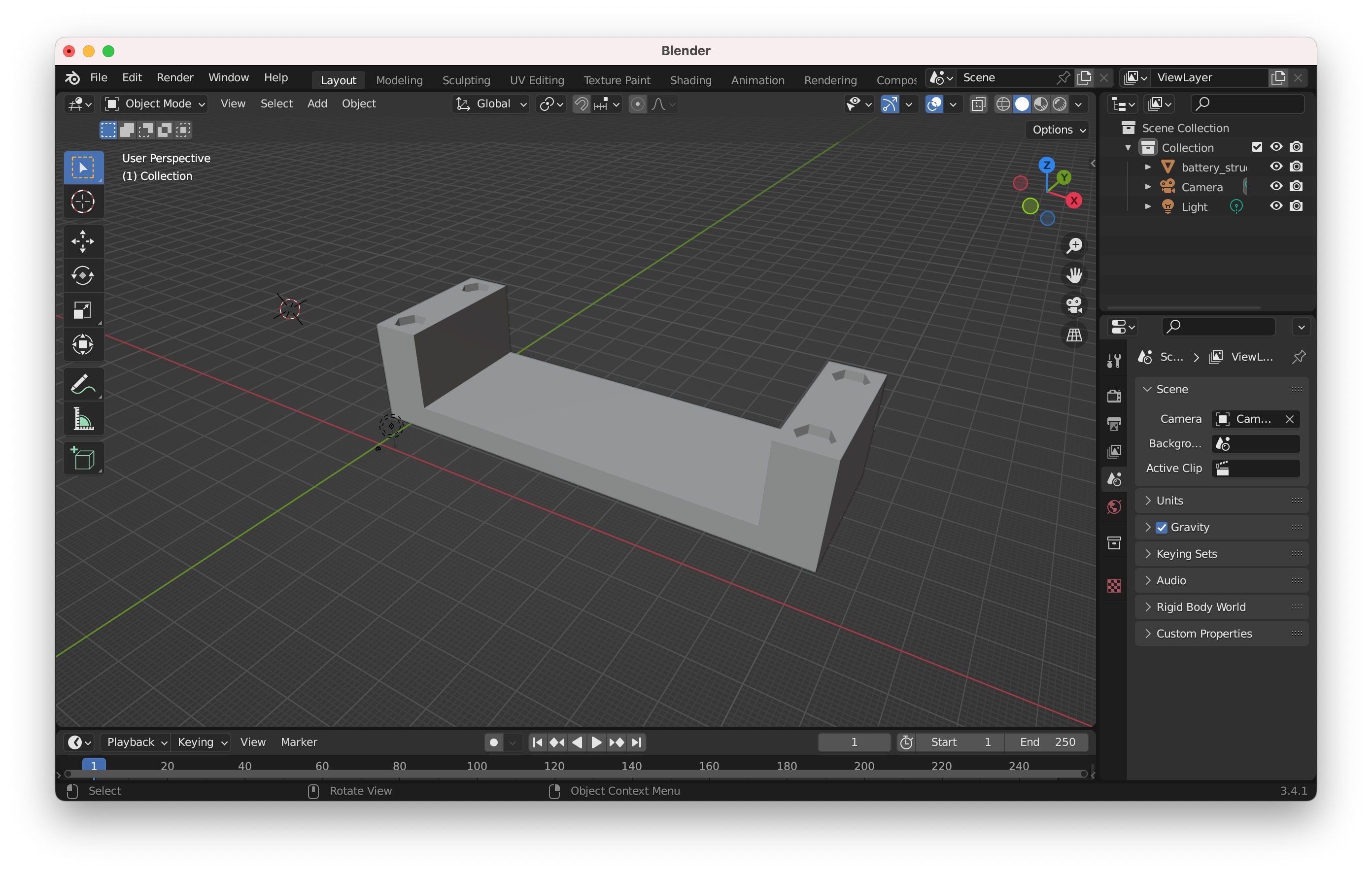
Supports
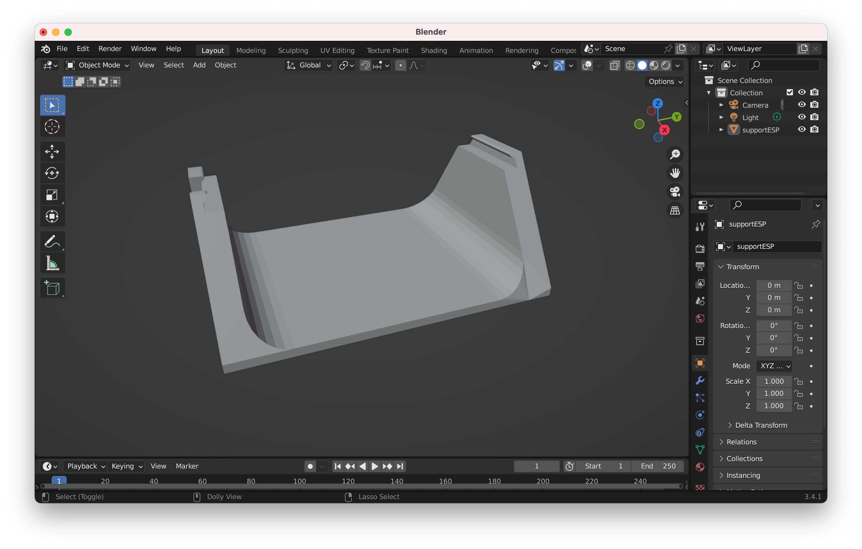
Creating the supports for the battery and the PCB
To create the supports for the battery and the PCB I just measured them and created 3D models that accommodate both tightly but are also easy to remove, I printed them in white PLA with the same settings that I printed the capsule, except I didn't add any support. Then I attached them to the base with double side tape.
The PCB support has a little round wing to help the PCB to be kept in place, but also easy to remove. There is a little hole so that the switch to the program can be reached. The battery support has 4 holes that allow the legs of the battery to sit tight but is also easy to remove them.
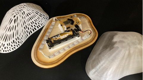
Integration
It was now time to integrate everything together!
Mounting
I started by adding conductive tape to the capsule and make sure the conductive tape matched the one on the base that was linked to the PCB.
Then, after soldering the neopixels in the shape of the base using wires to help them bend, I stuck the supports to the base by using double-sided tape.
I added the PCB, the battery and connected everything together... and it was ready!
→ Files Capsule here
→ Files Inner Capsule IDE here
→ Files Base here
→ Files Supports here
→ Files KiCad here
→ Files PCB images for the machine here
→ Files Arduino IDE here
Reflection
I planned the final project in a very methodic way (and documented as I go). In my Fab Academy experience, I always did the approach of prototyping things first using an already-made board, either Arduino or Barduino so I could fully understand what I was doing and how things would work, this has been the best approach for me, and in my final project it wasn't any different, I spend 50% of my time making sure the code and the input and output were working properly before moving into producing my own PCB. Because everything was working perfectly and I was really comfortable with the circuit I had no problems in designing the circuit in KiCad and manufacturing it, everything went pretty smoothly and it worked on the first try.
Regarding the shape of my object, it was the same, I had played with geometry nodes after we finish the 3D printing week (even printed a few more things) and was really in love with the organic mesh of the tutorial I was using so It wasn't really hard to do it, the fun part here is that I used my own hand to draw the shape itself! My learning here was that I added a lot of supports that weren't really needed and it was a waste of material and time, so luckily the printer ran out of PLA and stopped printing, so I started again with much less supports.
I didn't have any major setbacks and I believe it was because of the detailed planning, step-by-step, the prototyping before putting my hands on my own PCB and maybe a bit of luck as well ;) I was also really happy when I was walking around with my project and people got mesmerized interacting with it!