When we talk about input devices we talk about sensors. Sensors can be used to monitor or control something. Sensors collect a lot of data and we can transform that data into whatever we want, depending on our purpose. It's important to understand that to choose what sensor to use we need to understand what we want to do with the data.
Group assignment
For the input group assignment, we measured the signal produced by the voltage of an input device. We used a multimeter and an oscilloscope to measure this with a potentiometer. With the multimeter, we can measure fast signals and the resistance (ohms). By knowing the resistance we know how much an input device is consuming. The changes in the resistance are what change the ohms.
We used an oscilloscope where we added the voltage (previously measured with the multimeter) and added the time interval to see the waves. The waves shown are the signal of the potentiometer being used.
For this week I though I could start exploring my final project. For my final project I want to create a sort of hybrid musical instrument - that plays sounds based on what is sensing from a person (temperature, voltage, etc) so I though it would make sense to start exploring getting data from a human body.
What is a capacitive touch sensor?
Capacitive touch circuits rely on the change in capacitance a finger or body part has on the function of a circuit. The presence of a finger forms a parallel capacitance to ground that increases the value of the capacitor in the circuit. The human body introduces a small, parallel capacitance when touching circuitry.¹
There are two types of capacitive sensing: self-capacitance and mutual capacitance. Self-capacitance is where the touch sensor forms a capacitor to ground, and the circuit measures the change in its value when a finger is placed on it.¹
The human body forms a capacitance of somewhere between 100 pF and 200 pF. Replacing C1 in our circuit with a 300 pF capacitor and sweeping C2 between 100 pF and 200 pF, the output changes from 356 kHz with no human touch, dropping to 284 kHz in the presence of maximum human-body capacitance. ¹
This means we can measure how much capacity the intervention of human touch is, this is what I would like to work with for my final project, at least to start to understand how much this value oscillates and depending on what (assuming they do oscillate).
Exploring
I wanted to follow the same process I did for the output devices (exploring the circuit in Arduino first), so I started by look up the info page about capacitive sensing and its library.
Capacitive sensing with foil using Arduino
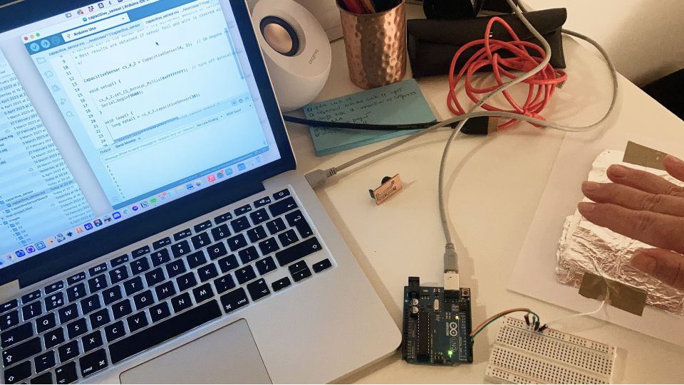
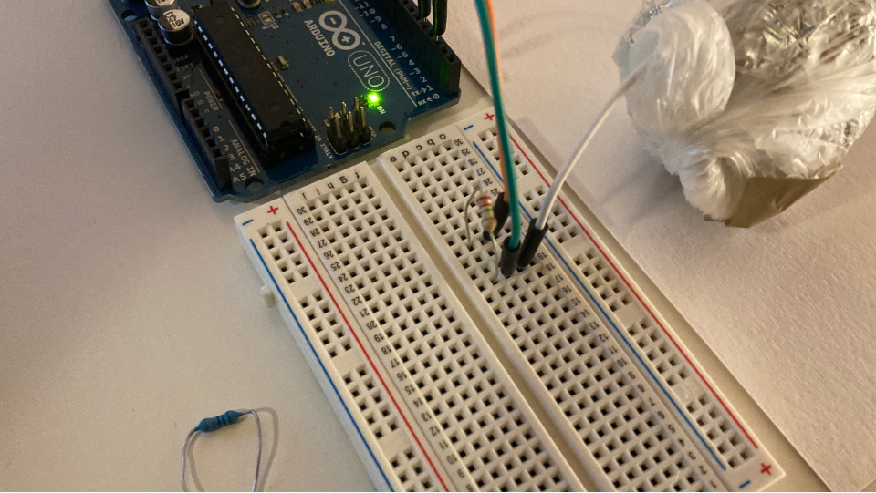
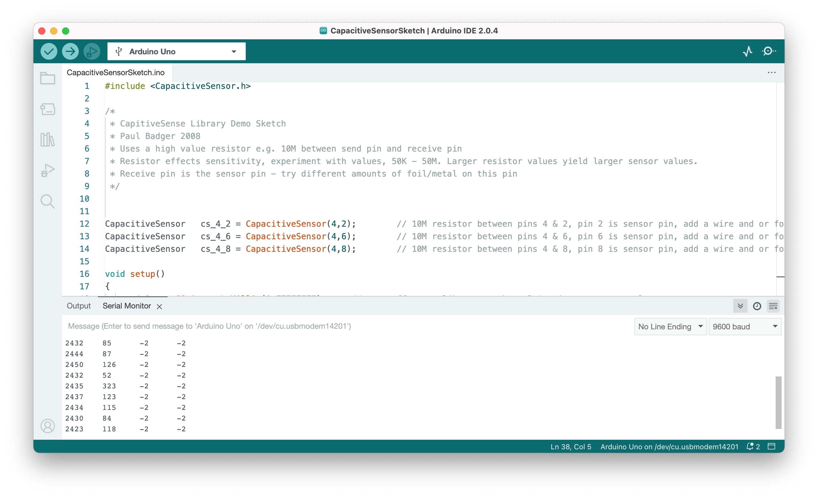
I started by doing a very simple input capacitive sensor using foil. I downloaded the capacitive sensor library and used the example code that uses PINs 2 and 4. PIN 2 is the input PIN - the one that reads the values from the capacitor (in this case the capacitor we created with foil powered by the hand).
This circuit is quite simple, I only used 2 PINs with a resistor(so that the voltage passing between our capacitive sensor and Arduino is not too high) and a conductive material that receives voltage from our hand - the capacitor. I read a bit about how it works here and here as well.
Explaining a little bit about the capacitive sensor...Our body has voltage, very little but it has voltage, so it's a source of energy. When we apply voltage to a conductive material such as foil it becomes a capacitor - a capacitor stores electric energy in an electric field, these values are being read by PIN 2. PIN 4 and PIN 2 are in a loop sending their states/new states, which means they will be more or less sending the same values, it's when we use our body voltage and the foil as a capacitor that we see the differences in data read. It is important to note that we should have our circuit grounded, having the laptop connected to the power socket is enough to avoid a shortage (that is what I did).
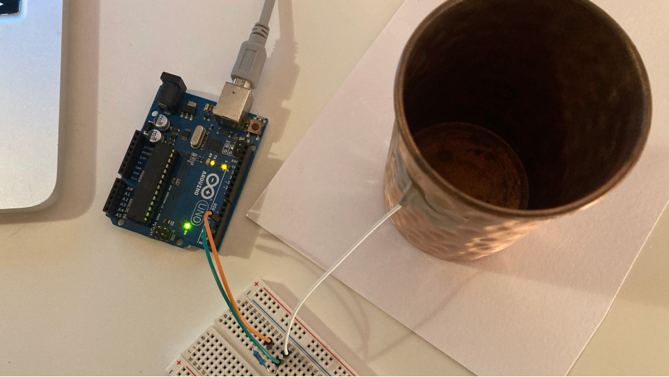
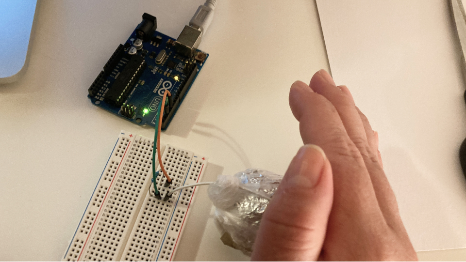
I also read the higher the resistor the higher the values we would get, in most places using a 10M ohms resistor was recommended, so I used one and connected everything according to the explanation....yet it didn't work...(I also realized latter the resistor I was using was 1 ohms and not 10M omhs as I though...) I tried with different conductive materials and also remembered to use plastic to isolate the conductive foil in the last tryout. Still nothing... as you can see in the picture on the left the readings are 0... Later on I removed the PINs I was not using from the code.
Changing the resistance
After a few hours of pushing the problem to the material and the code, I remembered that I had read that it is recommended to play with the resistance we are using...So I used a higher one - 50M ohms...and it worked!!!
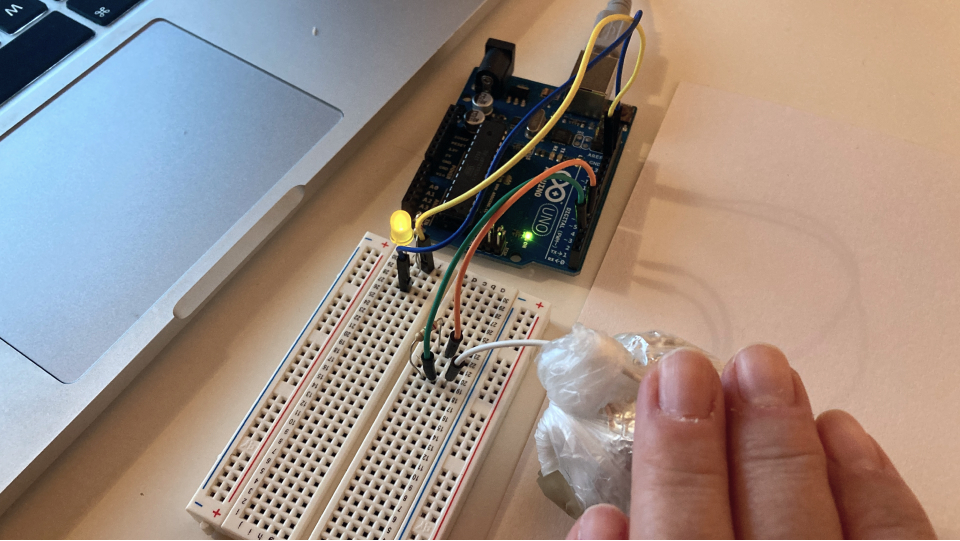
Adding an output
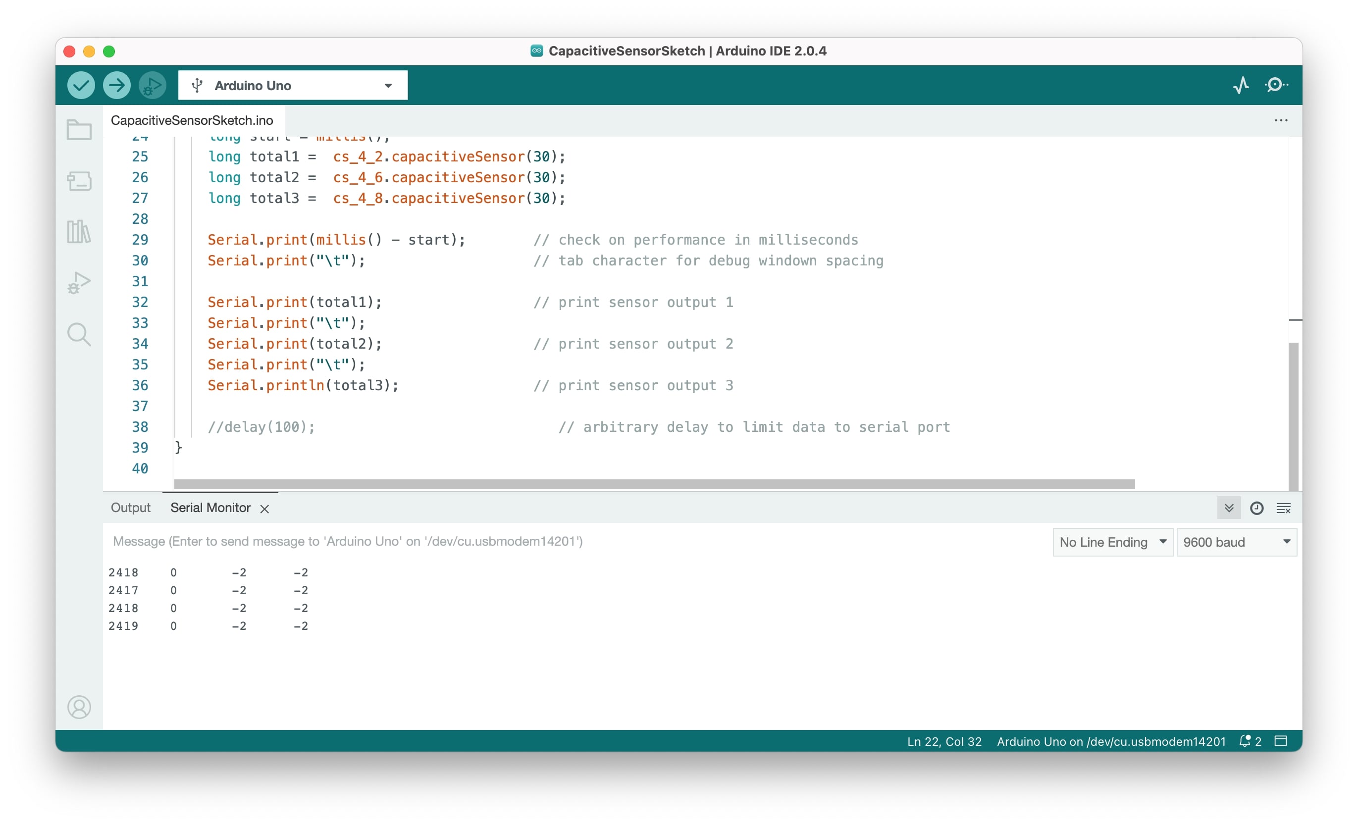
I was so excited that I wanted to go ahead and add an output as well, so I went to search for the BLINK code and added it to my code. I first tested the range of values more or less to understand which values represented when my hand was on the sensor. Without my hand the values ranged between 15-50 and with my hand they would go up to 200-400, so I added an IF condition to the loop. If the values are higher than 100 then the LED is HIGH (meaning, it lights up) if not then the LED is LOW (meaning it is off).
Designing the circuit
So now that I understood what to do I went ahead and started by sketching the circuit for my new board. I wanted to create a PCB that connects to the one I did before (and already has the SAMD 11 microcontroller), following the same process I did on the output's week.
Sketching
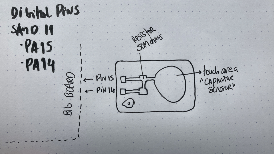
For this circuit, I needed to use 2 Digital PINs, and a resistor(50M ohms) and connect to the input PIN the capacitive sensor (conductive material that my hand can touch). The conductive material I wanted to use is the PCB board itself since it is made out of copper.
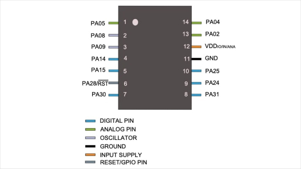
Because I wanted to connect this small board to the previous one I had done I took a look into the datasheet of SAMD 11 to make sure where were the digital PINs. The digital PINs are the 14 and the 15, so I considered them when sketching my circuit. Because they are side by side in the PIN heads it made my life easier.
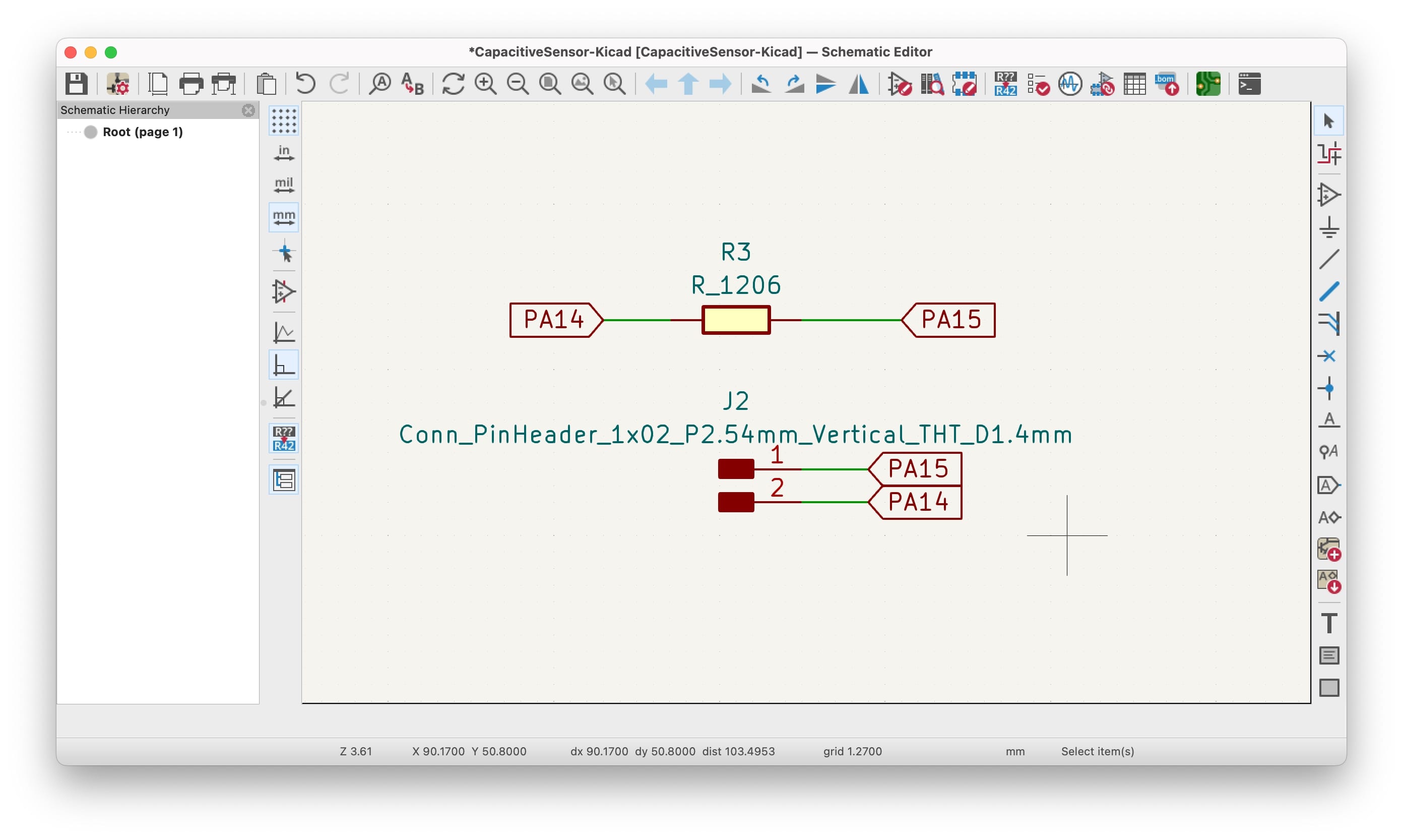
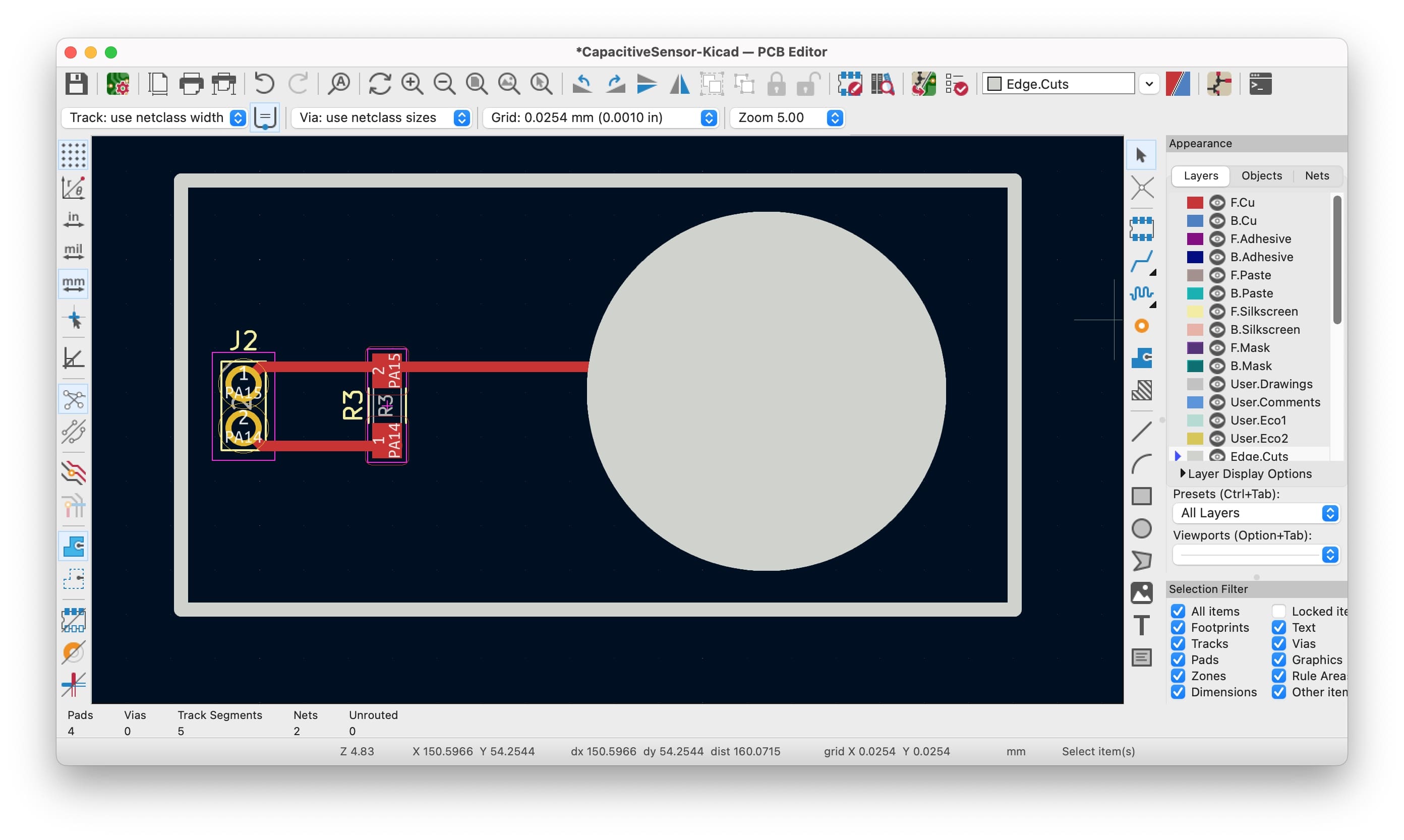
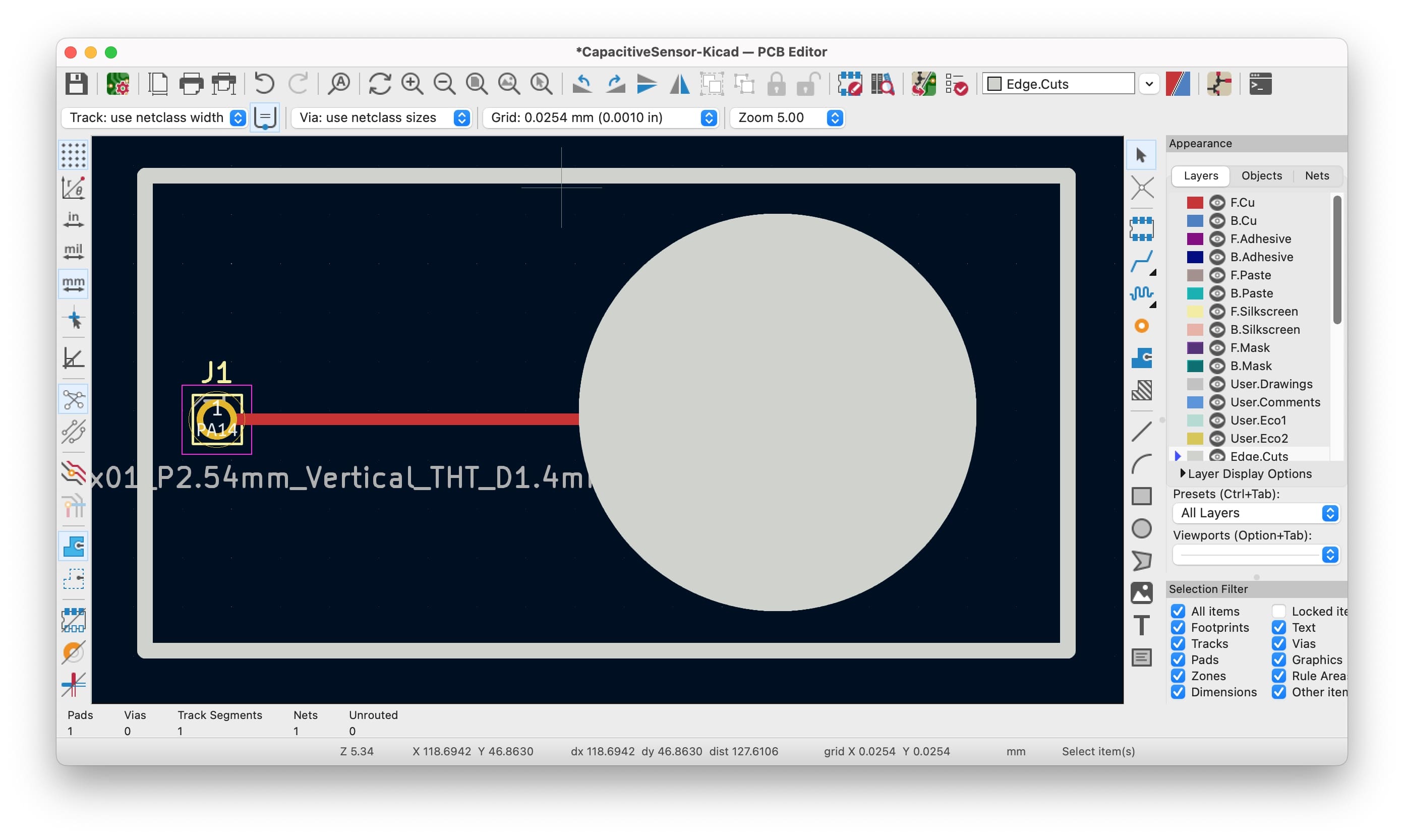
Doing the shematics in Kicad
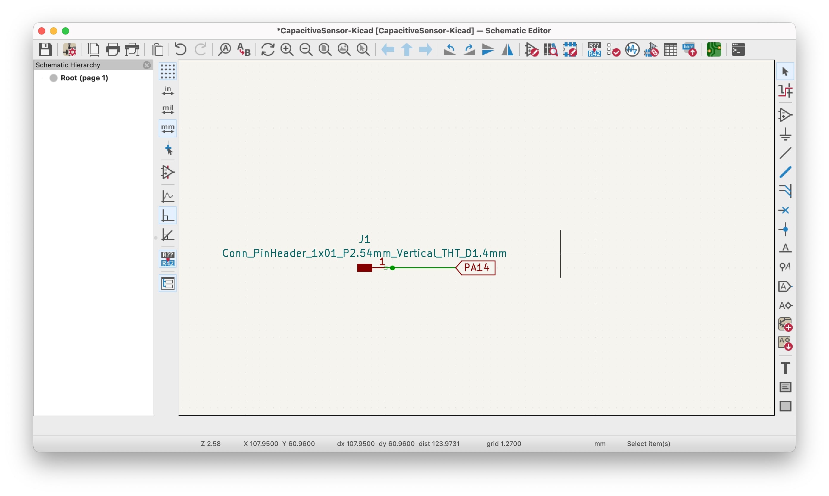
After I had a clear what I needed and what to do I went to KiCad and did the schematic of my mini PCB. I added 2 head PINs (vertical), a resistor, and a circle to represent the touch area of the sensor.
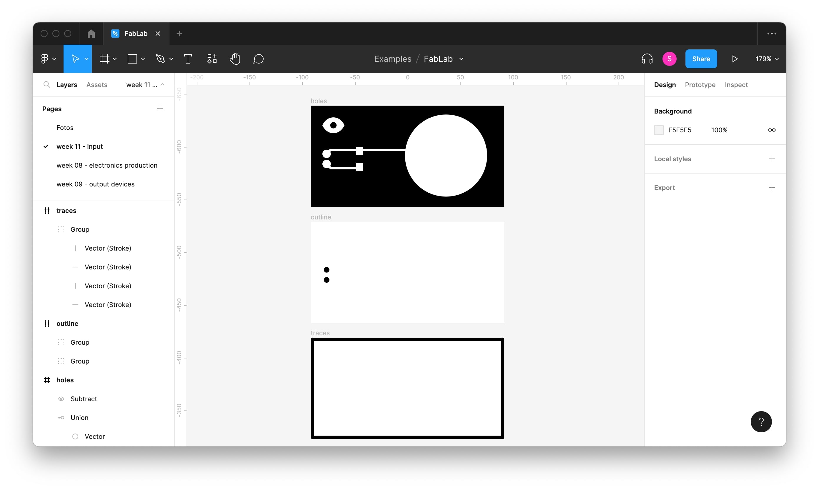
Preparing the files
Once I had exported my SVGs from KiCad I went to Figma to prepare the images for the machine. Important to remember that everything that is black will the erased by the machine and what is white it stays. Because Figma doesn't allow changing the dpi, I open the SVGs in Inkscape and update them to 1000 dpi (using the "export" tab parameters).
Checking the code in SAMD 11
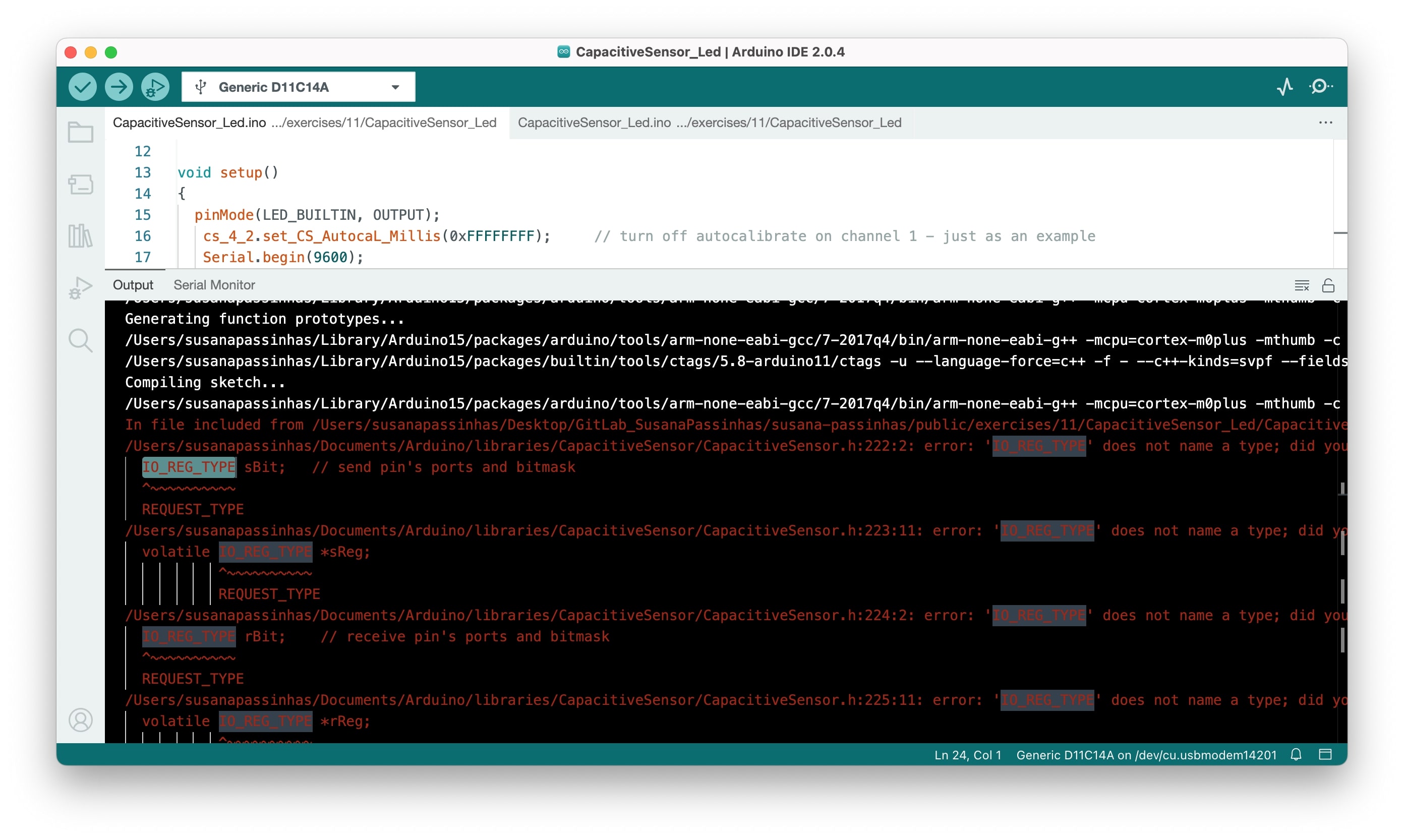
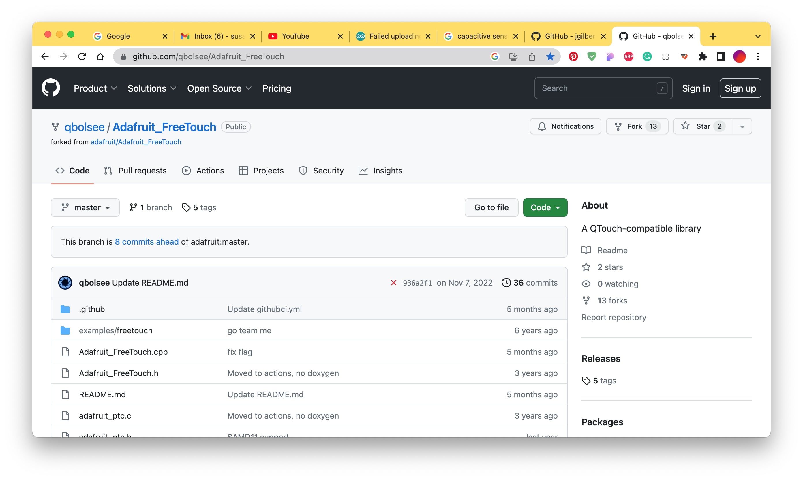
Before I cut the board I wanted to upload the code to my board (the one I would be connecting the sensor)...and it didn't work, there were a lot of errors so I couldn't use that library, therefore the circuit was not valid. The FabLab instructor told me there was another library for touch sensors created for SAMD... but it was for SAMD 21 not the 11 (the one I have on my board), luckily a student from FabLab had previously adapted this code for the SAMD 11, so I downloaded the adafruit freetouch adapted library here.
I uploaded the code to the board and it worked! So I also added an output, an LED that lights up when the sensor is being touched. The sensor continues to be the PCB itself but this time we don't need a resistor because the adafruit freetouch is embedding SAMD 11 capabilities (meaning we are using SAMD 11 resistor).
Preparing the files...again!
So now that I was using another code, the logic was a little different, I didn't need any resistor, only a PIN (that was "touch sensitive") and a conductive area linked to it. I follow the same idea as before and used the PCB itself, so, in this case, I only needed a PIN head to connect to the main board and that was it!
Once I got the SVG I went to Figma and made the color correct (black is everything that is going to be cut). Then because of the dpi I always go to Inkscape and export the SVG as a png with 1000 dpi.
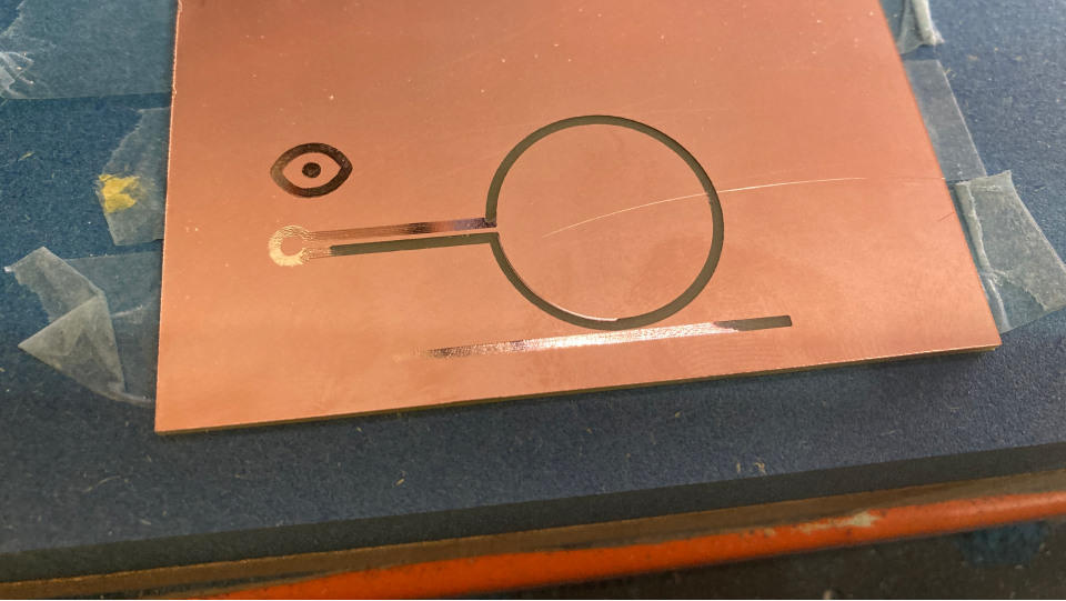
Manufacturing the board
To follow this board I used the same process that I have been using in the previous weeks when it comes to manufacture PCBs.
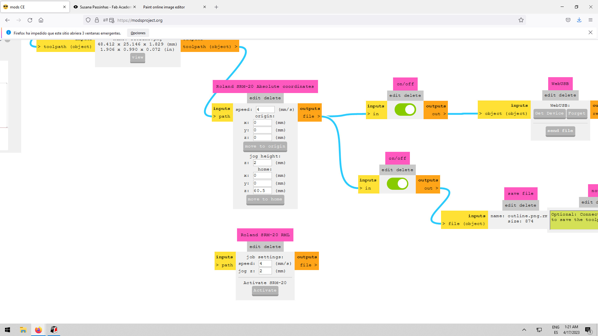
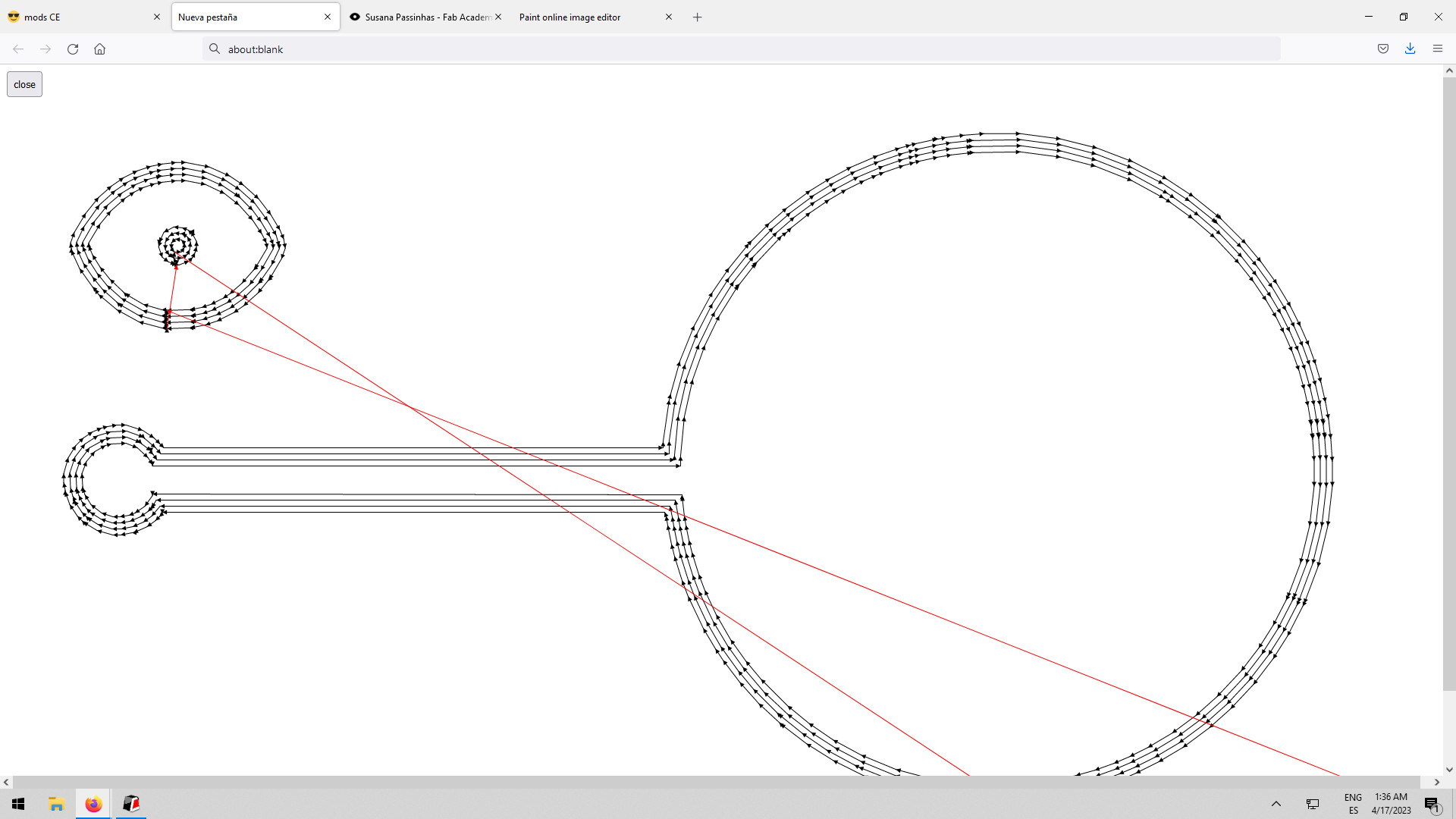
MODS
Before sending the files to the machine (SRM-20 mill) we need to prepare them using MODS. I uploaded the png images and defined the mill to be used, I used the endmill 1/64 (0,4mm) for the traces and the endmill 1/32 (0,8mm) for the holes and outline. I also made sure that the "origin" coordinates were all 0 and that in the "home" coordinates the Z was enough so it wouldn't scratch the board when moving, x and y are also 0 here. I double-checked the lines in the "view" after clicking "calculate". I saved the files and then went to the machine to calibrate it.
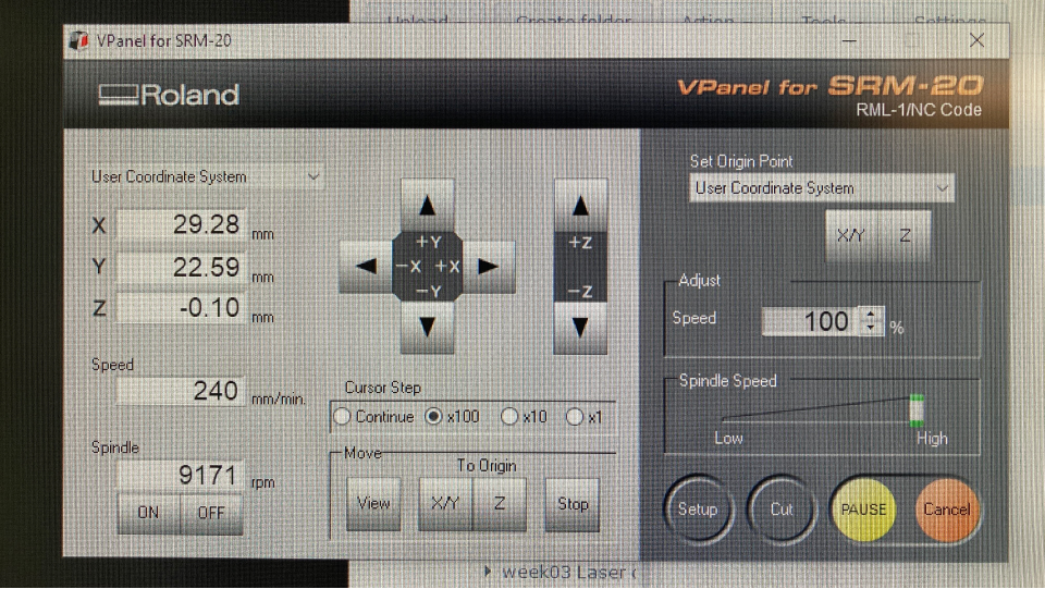
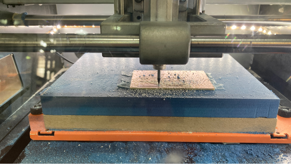
Milling
At the machine I followed the previous procedures, I glued the PCB to the bed of the machine with double-sided tape, then I added the 1/64 endmill to it, moved it to the x,y coordinates, and define them. Then I did the same process for the z, in the z we get really close to the bed but we don't allow it to touch, we do this manually so the endmill doesn't break. Once I got it I set up the z. Then I added my file by clicking "cut" selecting the traces and then clicking "output". I did the same for the other files, the output, and the hole, but in this case, I used the 1/32 mill and calibrated the machine again after changing the endmill.
Actually, in the first cut, I realized there were some parts that were not cutting well, so I stopped the machine and manually, put the spinner on and to 0 (moving in the slowest movement 0,01) and then one by one dropped it until -0,05 and defined that as my new z, then it cut nicely.
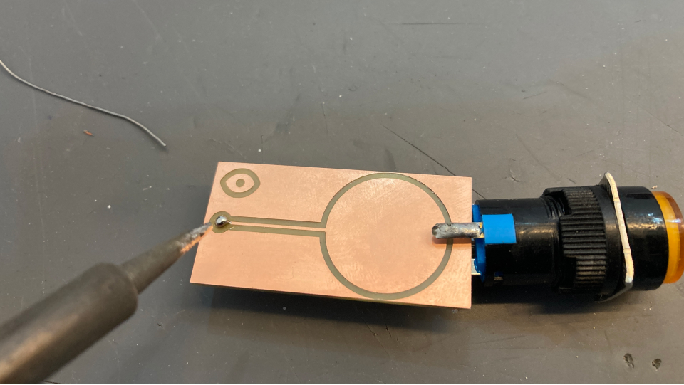
Soldering
I just needed to solder the pin head, so that was quite easy and fast!
For this mini board I used:
List of components
Coding with Arduino IDE
The code
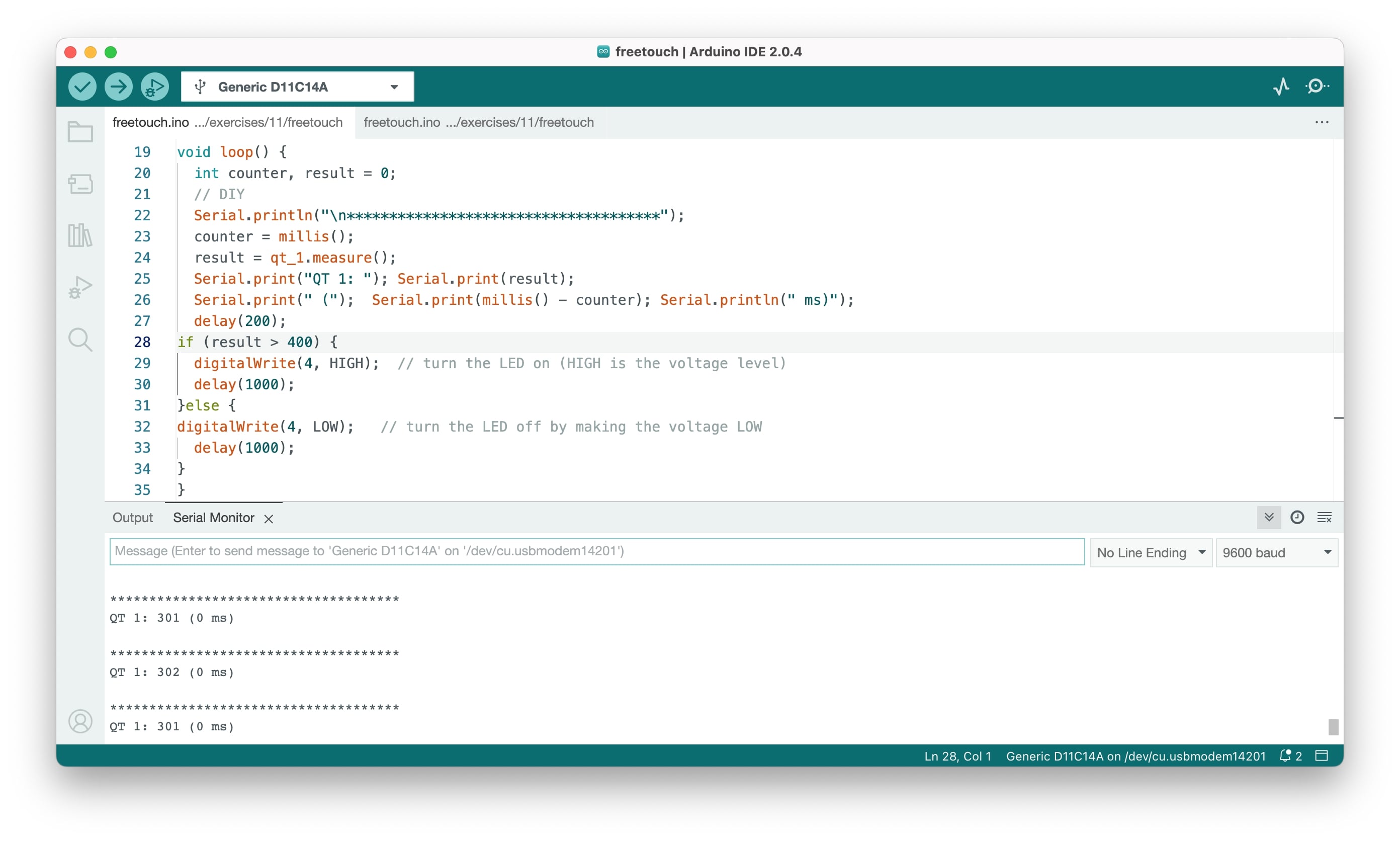
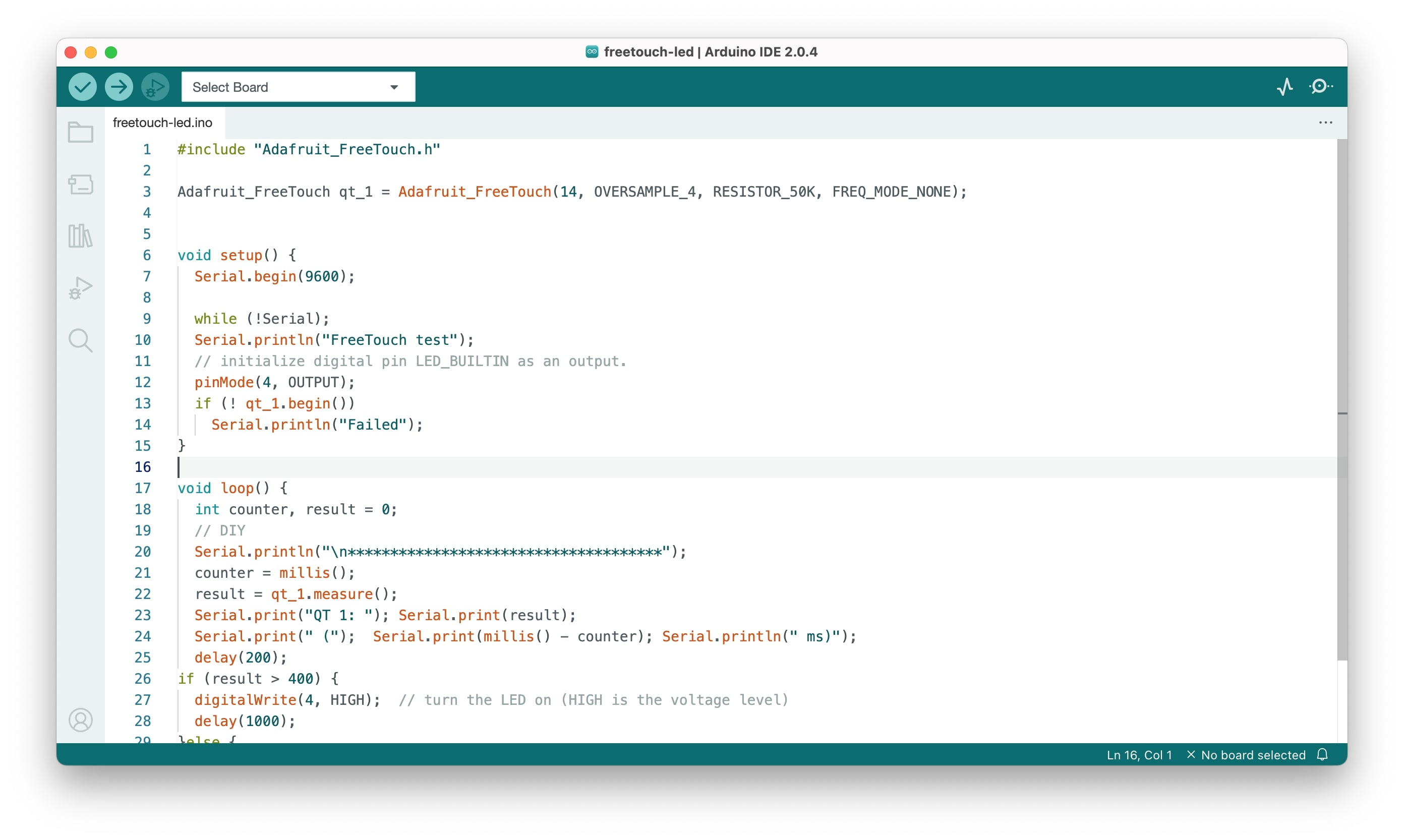
I just connected the board to PIN 14 (digital pin and also touch sensitive), using the code I had previously done and that was it! It worked really well. Regarding the code: we first call the library ("Adafruit_FreeTouch.h"), this library has already defined functions we can use such as the "RESISTOR_50K" one. We start by defining our variable the "qt_1", saying what is the pin, the resistor ohm, the oversample, and the frequency mode.
In the setup I define the serial port (so that the communication happens between the computer and the SAMD 11), I also define the LED PIN (4) and I have a "while" function here, to detect any errors when the code launches.
In the loop function, we count the values coming from the PIN 14 (qt_1) and I added an IF condition to it, saying that if the values are higher than 400 then the LED lights up. I defined the 400 based on checking the values with and without the sensor being touched.
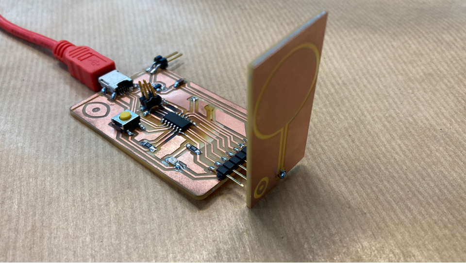
The result
I was really happy with the result and that everything worked out nicely! I am definitely going to use this in my final project as I want to do something with physical inputs such has the hand/finger.
This week went quite nicely, everything went well, I really enjoy the process of trying things in Arduino first to understand things and then going on to produce my own board. I also really like that I am using the board from the production week and doing these tiny boards that connect to it! Even though the board is a bit burned is working, but just in case I also milled a new board this week :D
Final project and input devices
Definitely will use the learnings of this week for my final project, as I already mentioned a couple of times in the documentation of this week.