09. Output devices


This week we learned about output devices, which are controlled electronically and convert power into motion (motors), light (diodes LED, electroluminescent wire) and sound (piezoelectric). We also talked about electromagnetism and how that works in different types of motors (DC motors and mosfets, steppers, servomotor).


Group assignment

An output device is any device we can be using as an output of data. In this week's assignment, we all measured our different output devices, I used a Piezo buzzer as an output. Output devices can have different power consumptions. Piezo buzzers normally consume less than 30 milliamperes (0.03v).

To measure the power consumption (watts) we use a multimeter to measure the voltage and multiply it by the current P = V x I. In the case of the Piezo, the power consumption is 65,2 watts (3,26v x 20amps).

It's important to know that in the PCB boards, the voltage is usually 3.3v, or an Arduino Uno board is 5v. It might be that our output devices require more voltage to work, if that is the case we need to connect an external source of voltage. If the voltage required is less we might need to add a voltage regulator between the device and the output so that the output device doesn't burn.

→ Group Page here


Exploring

For this week's project, I wanted to work with sound, so I decided to go ahead with the Piezo buzzer. To start I decided to explore a little bit first by using the piezo buzzer with Arduino UNO and Barduino.

This image wanted to break free...

Trying piezo buzzer with Arduino Uno

I started by searching for online tutorials that could help me get started. In this tutorial, I got the schematics. It seemed pretty straightforward. Using a breadboard and Arduino UNO we feed the board with 5v and the piezo buzzer connects 1 pin to GND and another one to a digital pin (we define that pin as the OUTPUT pin). We also use a resistor of 100 Ohm so that we make sure there is not too much voltage passing to the piezo buzzer.

Then I went ahead and added the code to Arduino IDE and uploaded it to the Arduino UNO board. I wanted to make it more playful and remembered that in the class we saw that we can even use music by using a library "pitches.h". I then went to check any songs that have been made already and used the godfather song as a song emitted by the piezo buzzer! Because the code was all commented I understood what it was doing without any problems.


This image wanted to break free...

Trying piezo buzzer with Barduino

Then I was also curious to do it with the FabLab board - Barduino. I used exactly the same circuit and went ahead to upload the same code. What I understood is that Barduino has less memory than Arduino UNO and it said it didn't have enough space when I tried to upload it to the board, I assume it was because of the length of the song. So I just used a simple short sound with a few notes. For the code, I used the Arduino example for tone melody, which uses the same library ("pitches.h").


Designing the PCB

Exploring the piezo buzzer in the Arduino UNO and in the Barduino really helped me understand the circuit and what I needed to design for this week's PCB.

This image wanted to break free...

Sketching

Because I also learned last week how important it is to think carefully about everything I started by sketching on paper the piezo buzzer connections. I only needed to connect the piezo buzzer to GND (-) and a Pin (+), I also added a 100ohm resistor as i saw it in the previous tutorials mentioned above. Because of the short circuit in the board on last week I though it was better to include it as well. I also saw that in the tutorials there was a connection to a 5v, which I was kinda confused since I was going to plug in to the previous board that was already being charged by the mini usb. Later I realized that the 5v was not needed for this board (neither for the tests in Arduino and Barduino).


This image wanted to break free... This image wanted to break free...

Doing the shematics in Kicad

Since I was still working on last week's PCB I ended up adding the circuit for the piezo buzzer on the board. I went back to my schematics and added a 12mm piezo buzzer (measured the one I was going to use) and made sure I added a connection to GND and another to a PIN - which I realized after testing it was causing a short circuit, so I designed a new board to connect to last week's board instead (that was working perfectly without the piezo).

FFor this board, I simply used the piezo buzzer with the - connected to GND and the + connected to the PIN. Then I added a female head that fits the male heads on the other board making this connection. I also used a 100ohm resistor between the piezo buzzer and the PIN head.


Manufacturing the PCB

Since I have been doing this since last week, this process was quite straightforward.

This image wanted to break free... This image wanted to break free...

Preparing the files

I started by preparing the files, this time what I did differently was to use Figma, then open Inkscape to change the dpi to 100 and then check the size. I only check the size and updated the Figma files with that size. I did this because in Inkscape it was creating a white line on the edge of the SVG. It worked perfectly!

Once I got the PNGs I went to MODS and added the images of the traces, outline, and holes. For the traces, I used again 1/64 (0,4mm) and for the holes and outlines I used 1/32 (0,8mm). I updated the origin coordinates to 0 and made sure to add a 15mm distance between points when cutting so the endmill doesn't scratch the board.


This image wanted to break free... This image wanted to break free... This image wanted to break free...

Milling

Then, once I had the files for the machine I added the board to the bed of the machine with double side tape. I also made sure the surface was really clean. I then proceed to set up the x, and y-axis by using the arrows in the machine and set it up. Then for the a axis, I moved the endmill as close to the board as I could (in the center of the board) and then with my hand loosened the endmill and made it drop until it touched the board, then I locked it and set up the z-axis in the machine. I then move the z up so It didn't scratch the board and clicked "cut", added the file, and clicked "output".

I did the same procedure for the holes and outline but with the 1/32(0,8mm) endmill. Everything went well and perfectly.


This image wanted to break free...

The components

For this mini board I used:

List of components
  • 1x Resistor 100ohm
  • 1x Piezo buzzer
  • 1x Pin Head 1x03 (female)

This image wanted to break free...

Soldering

This time I left the soldering iron longer (because I understood I was not leaving it long enough). It was nice to solder the piezo buzzer and the pin heads differently (through the holes).


Coding with Arduino IDE

This image wanted to break free...

The code

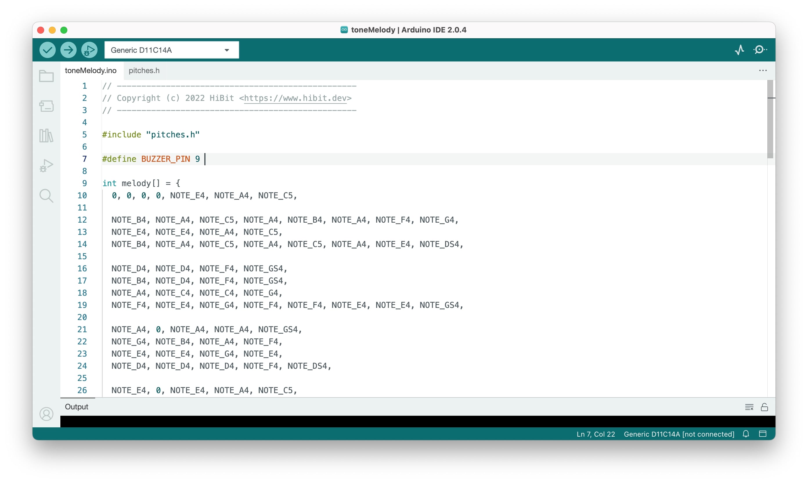
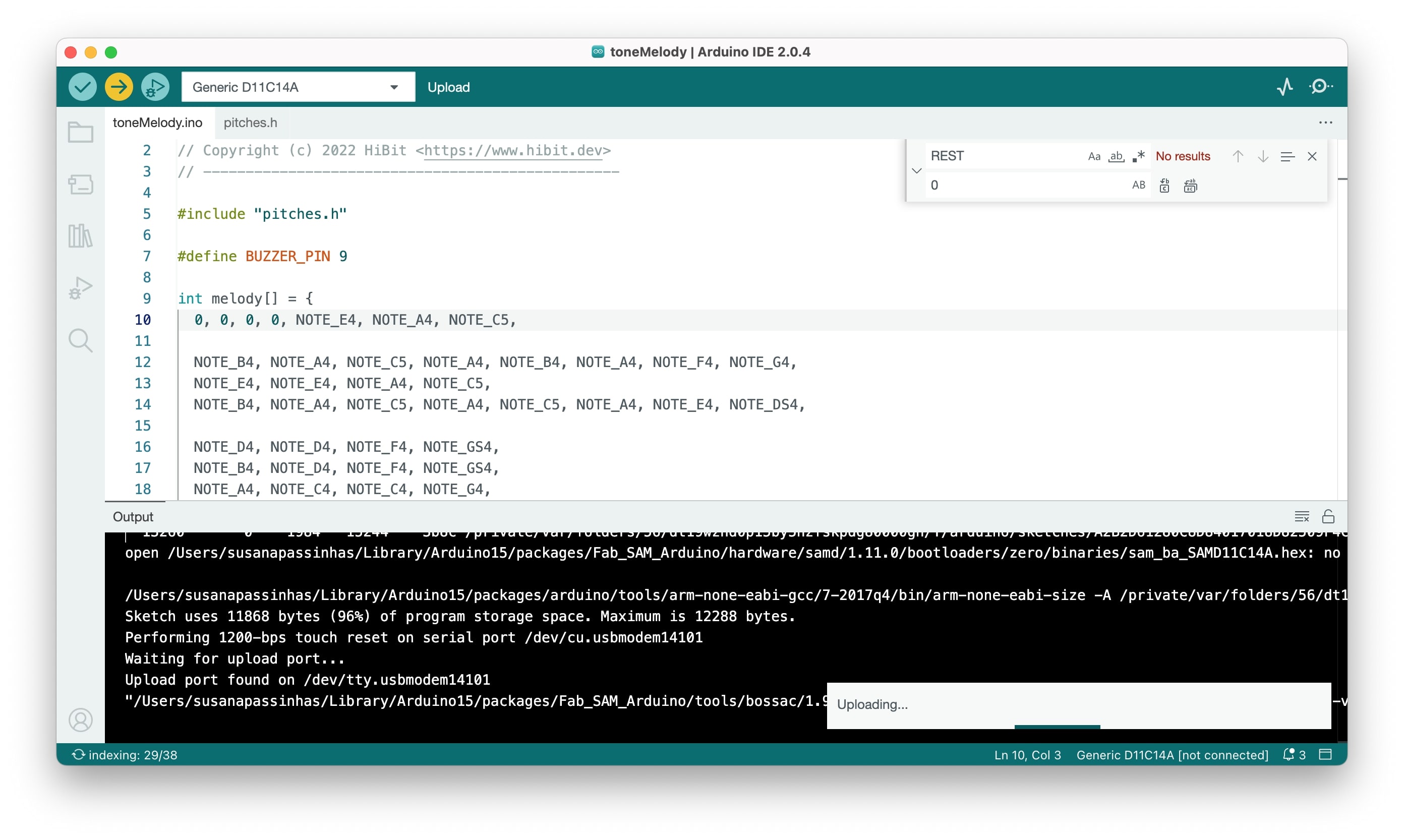
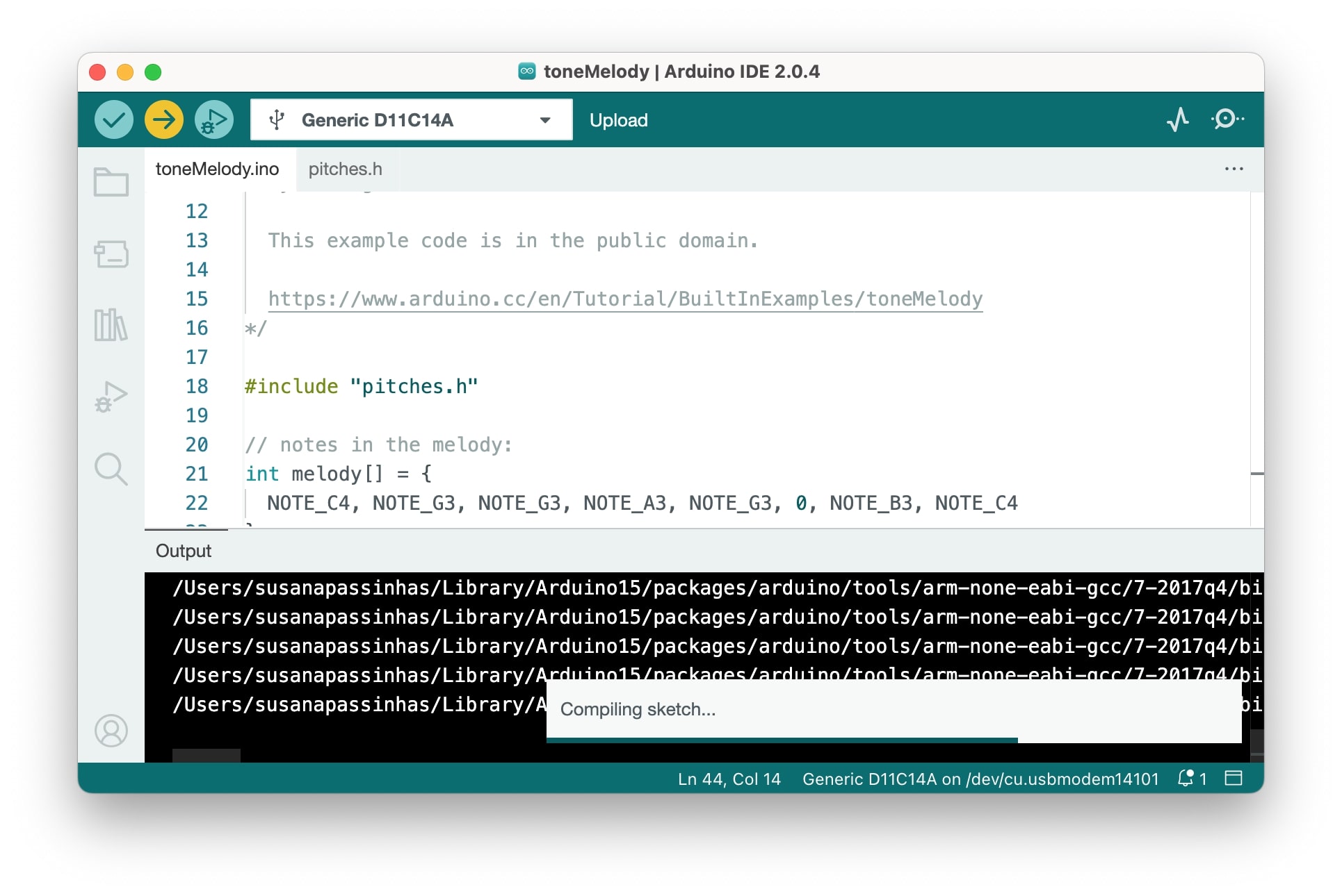
I was really eager to see if this board was working correctly after such a extensive debugging with the previous one! I went ahead and used the example code we already have in Arduino IDE for the tony melody and simply updated the OUTPUT PIN to match the one I have.
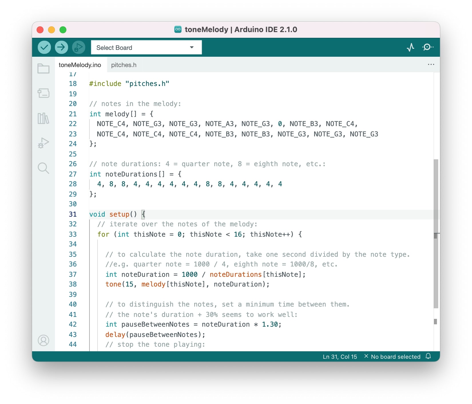

The result

...and it worked!!!! I was honestly so happy that I did this on the first try after such an exhausting debugging with the previous board that I though I would cry! Definitely would be interested in exploring the code more, but because I only had 1 day to do it I feel quite satisfied with the result.


→ Design files here


Reflection

Manufacturing this board was really straight forward as I had been manufacturing a few boards for the previous week. The circuit was really straightforward and I made sure I was soldering properly by leaving the soldering iron longer. I was really happy that everything worked!