Week 4. Electronics Production
Before the Start
Introduction 🖊
This week relates to electronics production. We will learn how to fabricate PCBs. In order to do that, we will use a very small and precise milling machine. We will also need to solder the components in the board. Luckily Erwin introduced us to soldering during the Bootcamp!
Fab Assignments 📚
-
Group assignment:
- Characterize the design rules for your in-house PCB production process: document feeds, speeds, plunge rate, depth of cut (traces and outline) and tooling.
- Document your work (in a group or individually)
- Document your work to the group work page and reflect on your individual page what you learned
-
Individual assignment:
- Make an in-circuit programmer that includes a microcontroller by milling and stuffing the PCB, test it to verify that it works.
My Goals 🎯
-
What I think I already know:
- I learned in school about electronics theory but I don’t have experience with electronics fabrication. Seams that is going to be a nice challenge!
-
What I want to learn:
- I want to learn the basics of electronics production, following the assignments from the FabAcademy, and if I have left time I will try to experiment with other materials to make the boards.
Project Management
| Task | Time | Day |
|---|---|---|
| Research | 2h | 16, February |
| Characterize the small milling machine - Group Assignment | 4h | 17, February |
| Mill the PCB boards | 2h | 18 February |
| Soldering | 2h | 18 February |
| Testing the PCBs | 1h | 18, February |
| Documentation | 8h | 21 /22 February |
Research
Attached are some profiles which I investigated before the starting of the week in order to have a cleaver idea of What I can do / What I want to do:
- Arman Najari - Barcelona, 2020
- Antoine Jaunard - Barcelona, 2020
- Nicole Bakker - Amsterdam, 2021
- Harm Van Vugt - Amsterdam, 2020
During the Process
Results 🖖
Group Assignment
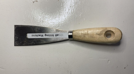
Tool to determinate the end mill
Individual Assignment
FDTI
UPDI-3
SWD D11C
Group Assignment 🏊♀️ 🏊🏾 🏊🏽♀️
I did my group assignment together with Benjamin, Jonathan and Sander.
The purpose of the group assignment is to set up the milling machine, in order to make a tool which we can be use to determinate the end mill.
Milling Machine Basics
Before the start, we learned the basic principles of the milling machine.
The milling machine for PCBs that we have at the Waag is the Roland Modela MDX-20.
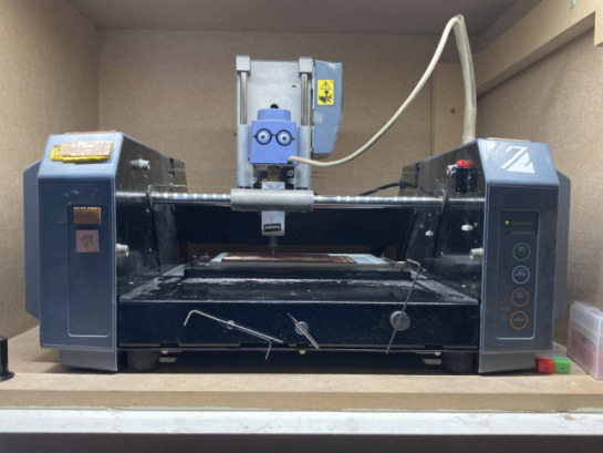
Henk showed us how to replace the Cu top plate with a new one. In this way, the machine is ready to use for the first tries!
The 4 Plates
The milling machine bed is made of 4 layers:
- 1st Layer = Machine base plate - made of acrylics.
- 2nd Layer = Baseline plate - made of acrylics.
- 3rd Layer = Sacrificial Cu plate.
- 4rd Layer = Cu plate for PCB.
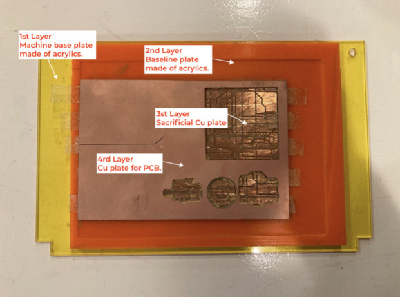
This is because two reasons:
-
The first two acrylics layers are because the bed needs to be very flat to make the PCBs come out easily.
-
The 3rd Sacrificial layer exists because sometimes the milling machine cuts further. In this way, we ensure that the acrylic beds are not damaged.
The two top Cu plates are glued to each other using a double face tap.
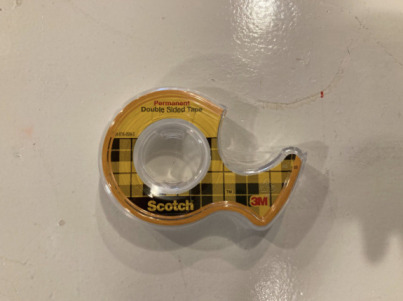
Cleanning the Plates
Its very important to clean properly the Sacrificial Plate from the remain tap residues when we remove the top Cu plate. In this way we ensure that the top plate will be glued to it right.
In order to clean it, we need to follow these steps:
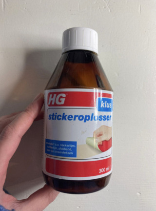
- Take off the glue residues with the spatula.
- If you want to ensure that is perfectly clean, use a “stickeroplosser” - dutch long name to call a chemical product that removes the glue from surfaces.
The Bits
There are different bits to operate with the milling machine. Depending of your needs you will use 2 main different bits:
- 0.4mm bits: Those are use to mill the traces in your board. There are two different kind of 0.4mm bits: with “1 Flute” and with “2 Flutes”, referring to the number of blades of the bits.
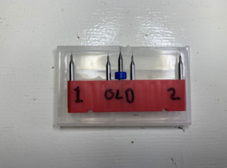
- 0.8mm bits: Those are use to mill the outlines of your board.
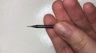
The first kind of bits are very tiny and brekeable. The second one are more tough.
Setting up the Milling Machine
To operate with the machine and make the group assignment, we needed to follow this steps:
- Download the traces and outile files which Henk shared with us.
Traces draw

Outlines draw
- Change the milling bids. Firstly we used the “1 flute” bid of 0.4 mm to do the traces, secondly we changed it for the 0.8 mm one to cut the outlines.
For this assignment we could also use a “2 flute” bid, but this belogs to the other group.
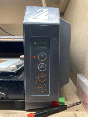
- Turn on the machine pressing the Green button.
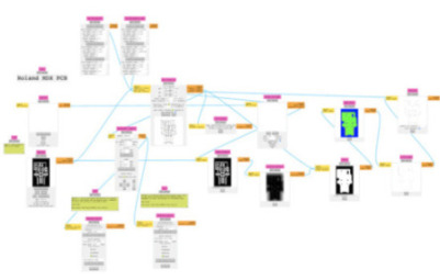
- Open mods with the terminal and tap:
cd mods bash mods
- Open the PBCs milling panel.
Right click > programes > open program > PCB
-
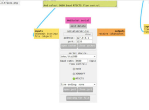
Because of the way the machine is conected to the mods, before setting up the parameters or selecting the png file, we need to press: close socket > close port > open socket > open port on the “WebSocket serial” panel.
-
Click the “View” bottom on the right side of the milling machine, in this way the machine will go to the origin.
- Open the PNG file.
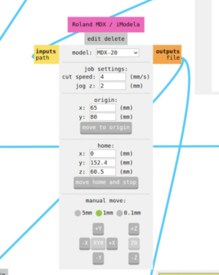
- Set up the X-axe and Y-axe origin in the *Roland MDX / iModela" panel.
-
Set up the Z-axe adjusting the bid by hand.
-
Change the parameters for the milling.
When milling the traces, change the following parameters in the Mill raster panel:
| Parameter | Number | Scale |
|---|---|---|
| Cut depth | 0.002 | in |
| Max depth | 0.002 | in |
Once you changed it, press Calculate
When milling the outlines, change the following parameter in the Set PCB defaults panel:
| Parameter | Number | Scale |
|---|---|---|
| Max depth | 1.55 | mm |
Once you changed it, press Mill outline (1/32), afterwods click on Calculate.
-
Click “send file” in the WebSocket serial panel to start the milling.
-
Some photos, mistakes and conclusions of the Group Assignment Task:
Tip 1: Turn on the machine before you open mods, otherwise the program will not work correctly. We had a problem with that ;)
Tip 2: Double-check always that the origin has been set up correctly. When you work with boards, you need to change the bits and the parameters are nice to write down on a paper the origin which you are using to don’t make mistakes!
Tip 3: In order to double-check if you chose the right parameters, you can click on the white View button. The machine will show you what it milled till that point. If everything is ok, you can click the button again and the machine will continue its work from where it stopped.
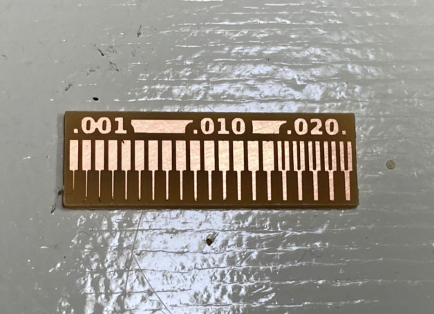
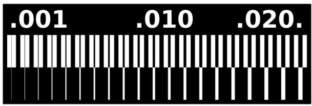
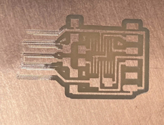
Tip 4: Use double flute bits to make the traces of your board. We resulted with the group assignment that actually they are much more precise rather than the 1 flute ones. You notice it in the following photo:
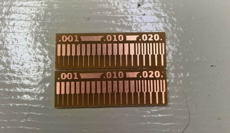
As it can be seen in this board, the limit of our “1 Flute” and “2 Flute” bits for cutting trees is 0.020 in.
Individual Assignment Process 🏊♀️
For the individual assignment I cutted and tried 3 different boards:
- FDTI board.
- UPDI-3 board.
- SWD D11C.
In order to do that, I followed the same steps which I previously explained for the group assignment.
Considering that the “2 Flute” bid has higher precision rather than the “1 Flute” one, I used the 0.4 mm - 2 flute bid to cut the traces, and the 0.8 mm bid to cut the outlines.
Tip 1: If you want to be sure of using the correct components. Double-check the component you are taking from the box with the component used in the “sample board” you will probably have at your fablab. Sometimes students put back the components in the wrong boxes and there is the possibility of having them.
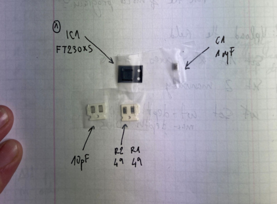
Tip 2: Once you have all your components, make a draw, and tap them to a paper, writing next to them which one is it. In this way, you will make your work easier and more efficient.
Attached an example of the FDTI development.
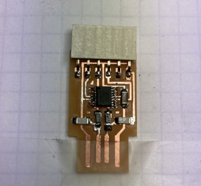
FDTI
During the milling process of the board, I didn’t have any problems, but during the soldering I had some troubles adding the microcontroller.
Since I used too much soler, I needed to use the heating gun machine to remove the piece and stick it again to the board.
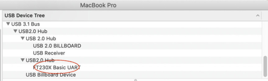
After a few tries, my computer was able to read it! What a time to be alive.
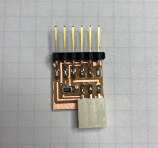
UPDI-3
This was the easier board to assemble, since there are a few components, and the soldering results were quite easy.
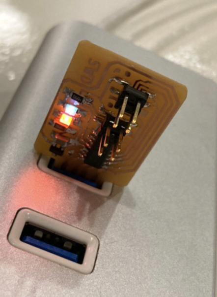
SWD D11C
This was the board where things went a bit more complicated. :/
Firstly, when I tried to mill it, the Cu plate was not flat in all the points of the board - especially on the corners, this is why the traces were not visible at the first beginning.
I tried to level the bid to the area with Bente, and try to mill the piece again. This resulted in breaking the bid. Probably because of
I needed to mill again the board in a new Cu plate another day. This time everything worked out perfectly.
When soldering the components, I had to re-solder one of the pin headers (J2), because it was not correctly soldered to the board. Also, I had to replace the R1, R2.
Finally, Henk helped me to add a program he already had to the PCB. I worked and the LEDs shined perfectly.
Retrospective 🤔
I have experienced this week less experimentative/creative compared with the previous ones.
I did not have much idea about PCBs, how to mill them, and how to solder their components, so I learned lots about those processes.
The mistakes that I had were mostly related to soldering, rather than milling. I fix them easily, also thanks to the help of Jonathan and Henk. Who showed me how to stick out the components using the heating gun.
I’m curious about designing my own boards.