Moulding and casting this week. Machines play a role but not a big one (or so I thought)
to learn / to do
Group assignment:
- Review the safety data sheets for each of your moulding and casting materials
- Make and compare test casts with each of them
Individual assignment:
Design a 3D mould around the stock and tooling that you’ll be using, mill it (rough cut + (at least) three-axis finish cut), and use it to cast parts.
looking ahead
what I already know
I know a bit about moulding and casting from the goldsmith school days. We poured molten metal in different kind of moulds: sand, sepia and gypsum. These moulds were used only once, although we also had rubber moulds that we used in the lost wax method (a cire perdue)
what I want to learn
I want to use this week to test out a few ideas I have for my end project: The Tide Clock. I am thinking of creating a translucent “clock” face with leds behind it. This week I can run some tests in thickness of the material, how translucent it should be, the effect of it on led light behind it.
I want to use my own small 3018 CNC to mill the wax, so I can get comfortable in using it.
the process
group assignment
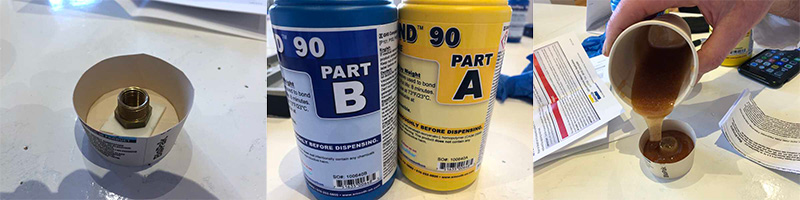
For the group assignment I teamed up with Saco. We wanted to cast with one of the sturdier materials, and the urethane mould that Henk has showed us looked promising. So we grabbed a packet of Ure-bond 90 and went to work.
Reading the safety sheet I found the following warnings:
- Use it in well ventilated (room ventilated) area’s only
- When in contact with skin: rinse carefully under streaming water
- When in contact with eyes: rinse carefully with water, seek medical advice if neccessary
- When swallowed: seek medical advice (tip form Henk: take the safety sheet with you)
This is a two component material. The pot life of Ure-bond 90 is 8 minutes, meaning we have 8 minutes after combining the two components before it hardens too much to cast with it. It has a total curing time of 16 hours, but is hardened enough to handle after 4 hours.
I also read that this material was used to form a bond (glue) between different materials. That seemed odd, because that did not sound like castable material at all. But since the carton box this Ure-bond 90 came in had colorful pictures of casted toys on it, I just assumed this material could be used for both casting and bonding.
So we went to work. We chose a nut as casting mould, and used some double sided tape to attach it in the bottom of a cup. We then followed the procedure that was stated in the manual: use equal volume amounts of components A and B, first stir component B, then add component A, stir for a good three minutes.
We calculated the amount of material we needed by measuring the diameter of the cup and using pi to calculate the area. We multiplied that by the height of the cup to get the total volume. We divided that by two, since we needed equal volume amounts of both components. Then we realised we did not have a measuring cup to measure the amounts, so we just used another cup and estimated the amounts.
During stirring, I felt the material warm up. An exothermic reaction, apparantly.
When the 3 minutes were over we poured the material in the cup. Little air bubbles started to form. We had seen this also in the urethane mould that Henk has showed us, so we were prepared. There was a vacuum chamber, ready to be used to get out those airbubbles.

We put our model into the chamber. I used some leftover Ure-bond 90 to pour into a bottle cap that we did not put in the vacuum chamber, so we could compare the results of both methods.
In the chamber, we saw the level of the material rise, and we saw a lot of bubbles come to the surface. They did not however vanish, but kept stuck in the material that started to look more and more like a muffin or a souffle.
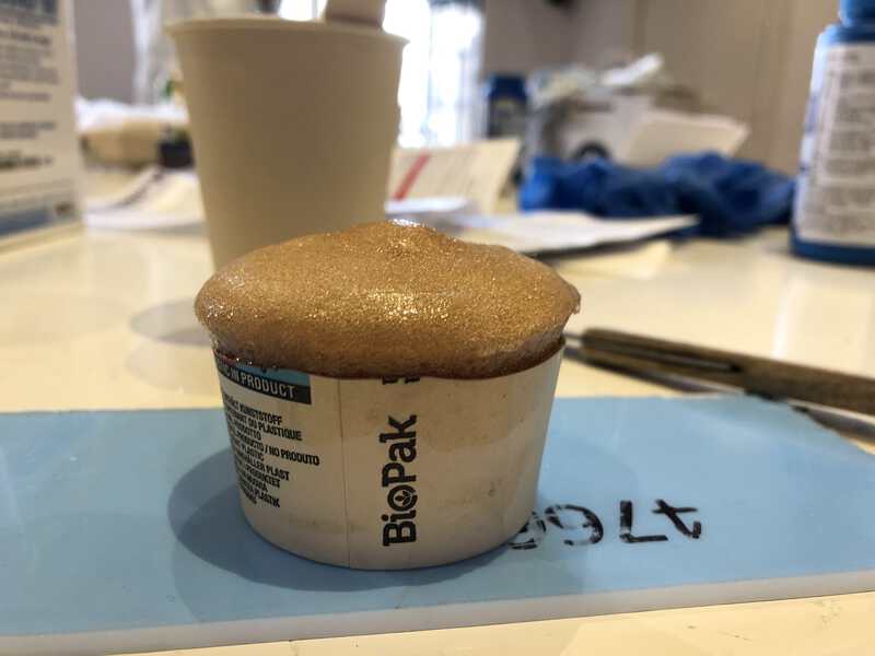
After a good 10 minutes nothing happened anymore, and we got the model out. We put it together with the bottlecap in the cabinet with the fume extractor. Ready to wait about 4 to 16 hours to see what had come of it.
But already after 30 minutes, the material seemed hardened enough to remove the paper cup and bottlecap. And was more, the material seemed much too rigid, almost brittle. After removing the cup, we were left with a rather useless rigid material with a nut in it. The material in the bottlecap did not look like a souffle, but was equally rigid. But it looked better in terms of airbubbles.
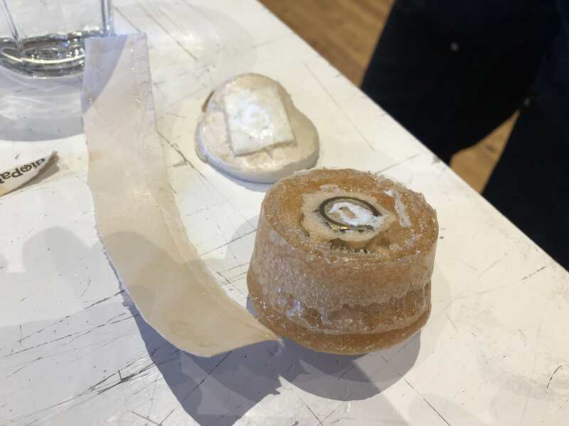
I thought that we maybe made an error with the mixture and did not use exact equal amounts enough. But then I learned about how casting materials have a number that tells you something about the rigidity of the final cast result. 10 for example means not rigid at all. Kind of floppy, if it was thin enough you could blow it up like a balloon. 30 or 40 is still very flexible. 60 starts to become less flexible. The scale goes up to 100. And now I know that the 90 in Ure-bond 90 means that it is a very rigid material once cured. Also, Ure-bond is really a bond. Frankly, I wonder why it is in the cabinet with casting materials.
individual assignment
This week’s process will consist of three steps:
- Create a positive model with 3D axis machining (we will use the CNC mill)
- Use this model to create a negative mould
- Use this mould to cast the positive end result
We will create the positive model in the first step with a CAD program, in my case with Fusion360.
This 3 steps of casting is mainly used when the end result you want is from a rigid material. You then use the positive wax model to cast a flexible mould. The flexible mould is used to cast the rigid material, because it’s easier to remove it from the rigid material afterwards.
If you want to cast a flexible endmodel, you can do this with the machinable wax, because a flexible model is easy to remove from the cast.
Positive wax mould
Fusion360 (again)
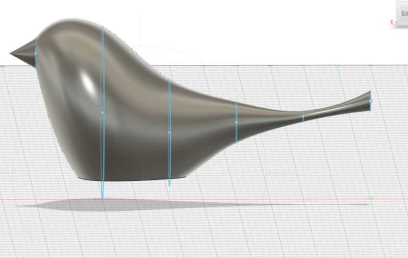
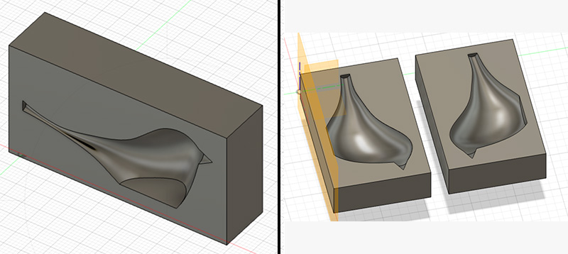
The first step in the process is to create a wax mould that will be milled with the milling machine. And so I need a 3D design for that. I want to create a double sided mould, and as final shape I choose a little bird. I am toying with the idea of adding a little light in its body, so it can be illuminated at night.
I start out with Fusion360, as this is by now the 3D program I understand best. I find a tutorial for creating a little bird shape here, using offset planes, circles and loft. I use a guide rail to shape the bird a bit more. This takes me a lot of time, because the guide rail does not want to snap to the cicles in the perpendicular planes. I finally find a solution that really works: projecting the circles into to rail sketch, by using Project > Intersect in the rail sketch, and selecting each circle.
When I have the bird ready, the process begins to convert it to a millable mold. But first, there is some calculation to do. These are my constraints:
-
I have a wax block that measures width:145mm, height: 95mm and thickness 30mm.
-
I want to make a double mould, which means that the height of my waxblock determines the width of my bird. Also, half the width of the block determines the height of my bird. And since each mould is half the thickness of my bird, it can be as thick as twice the thickness of my block.
-
I want to have 10mm thickness of the walls on eacht side, because I know it is hard to get the millhead of the ShopBot at an exact location (it has a jogsize of 10mm and I have not found a way to change that).
-
I want to have a wall of 5mm between the two moulds.
-
Just to be sure, I also aim for a bottom that is 10mm thick, although that is more than necessary.
-
I want to use a tool / endmill of 5mm, which means that there should at least be a gap of 5mm between my model and the walls, otherwise the mill could not clear that space
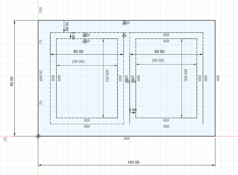
Based on these calculations, my model can have a maximum width of 65mm and a maximum height of 50mm. The thickness can be maximum 40mm ( 30mm thickness of the block - 10mm bottom leaves 20mm for each halve, so 40mm in total )
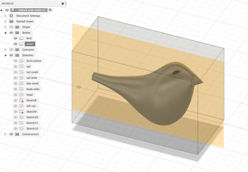
After scaling down the bird model so it fits in these maximum sizes, I start with what I call the inner mould: the cave around the model that will be milled out.
First I draw a rectangle around the bird, keeping the constraints in mind. I use the extrude function to convert the rectangle to a rectangular box around the bird.
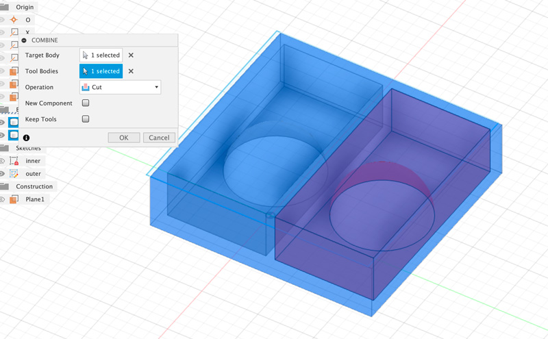
Now I need to hollow out the bird model from this box. I found this youtube tutorial really helpfull for that. I use the Combine tool for this (Modify -> Combine). For Target body I select the box, and as Tool body I select the bird, I use the operation Cut, as I want to cut out the bird from the box. In the screenshot I have set the transparency of the box to 50% so I can still see what is happening inside the box.
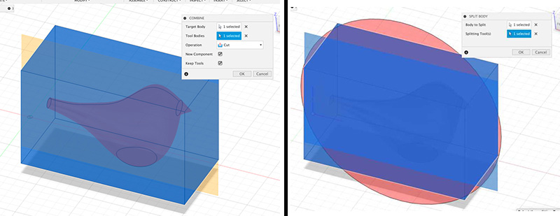
After clicking OK I have a new component that consists of one body: the box with a hollow birdshape in it.
To divide the box in half, I use a Midplane and the operation Split Body (Modify -> Split Body). I use the Midplane as the Splitting Tool and now I have two halves of the ‘inner mould’
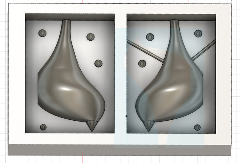
Now I need to add registration points on both sides, so that both halves of the final mould can be put together in the correct way. For this I use Cylinders that I give a size of 6mm. This is a result of trial and error, as I first tried spheres and also tried smaller cylinders. But as we will see later on, the shape and size of the regsitration points are determined by the size of the endmill and you will run into problems when you use something smaller than your tool.
Also, even though I write this process in a linear way, in reality there was a lot of going back and forth between the different stages of model, inner mould and outer mould, splitting and combining, because initially I had forgotten about adding the registration points and vents.
I add the cylinders on one of the two bodies and use the combine tool to cut them out of the other body.
For the vents I also use cylinders, that I create as a separate body first so I can rotate them before I use Cut to cut them out of the model.
Now I do some rotating and moving of both halves untill I have them next to each other, with some space in between them.
Since the halves are still the ’negatives’, I need to convert them to ‘positive’. To do this, I again draw a box around the models. This time, the box has the size of my wax block. This is what I call the ‘outer mould’.
After drawing the box, I again use the Combine tool to cut out these two models from the outer mould. Now I have a model that is the size of my waxblock, with two positive moulds, with vents and registration points. Ready to be milled.
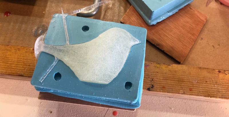
 the final mould, the birds have body in a hollowed out box
VCarve
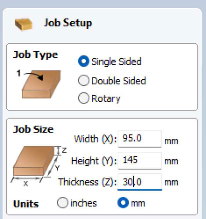
To create the toolpath for the Shopbot, I use VCarve. I export the model from Fusion360 to .stl and load this into VCarve.
In the Job Setup panel, I type 95mm for the Width (X) and 145mm for the Height (Y). These values have switched compared to my design. This is intentional, because the ShopBot at Waag has the X-axis along the long side, and the Y-axis along the short side
In the next panel, I play around with rotation and orientation of my model, so that it has the correct side up and fits nicely within the outline of the material:
- With TOP/BOTTOM etc you flip the model
- With Rotation Z axis you go from portrait to landscape
- Center model centers your model in the middle of the material
Next step is to generate the toolpath. I click on the “toolpath” tab at the right side of the window to open the Toolpath panel. First, I create a “roughing” toolpath. The function of this toolpath is to quickly cut away most of the excess material and leave enough material do do a finer cut afther this.
I select a standard 5mm flat two flute endmill for this and use te following settings:
Roughing Toolpath
- Stepover is 3mm (or 60%)
- Spindle Speed is 6000 r.p.m
- Feed Rate is 20 mm/sec
- Plunge Rate is 20 mm/sec
The stepover of 3mm is what makes this a job that cuts away a lot of material in a minimum amount of time, but it will leave the surfaces pretty coarse.
For “Machining Limit Boundary” I select “Material Boundary”. I set an allowance of 0.3mm and leave the rest of the settings to their defaults.
I press “Calculate” to let VCarve calculate the toolpath. Then I click simulate toolpath, to check what the milljob will look like. When the simulation is over, I immediately see two problems:
- My bird has gotten feet. This is because I somehow did not leave enough space between the bottom of my bird and the wall of the mould.
- The registration points are only milled on one side. This is because I made them smaller than the endmill, and so the endmill can not mill the holes for it.
I correct these problems in Fusion360. That is easier said than done, because I have to redo part of the combining and the splitting. But it gains me intimate knowledge of the history bar in Fusion360.
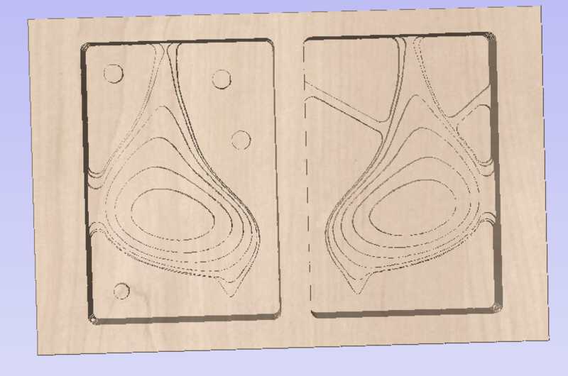
After correcting the errors, exporting the .stl, reloading the model in VCarve and running the simulation again, this time the result looks good.
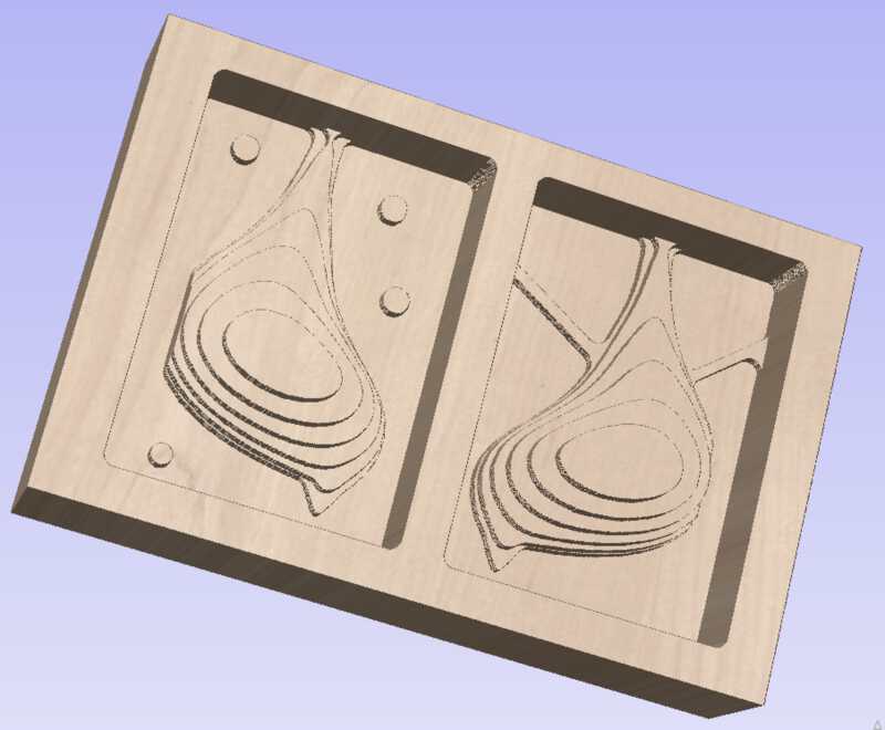 The result of the rough toolpath simulation. The stepover of 3mm gives coarse surfaces
Next, I setup the “finishing toolpath”. This toolpath is meant to add the final finer details. In my case, it uses the same settings as the “roughing toolpath”, with the exception of the Stepover:
- Stepover is 0.5mm (or 10%)
With this small stepover, surfaces will be much smoother, as is shown in the simulation.
I again select “Material Boundary” for “Machining Limit Boundary” and leave the other settings to their defaults. Then I run the simulation again:
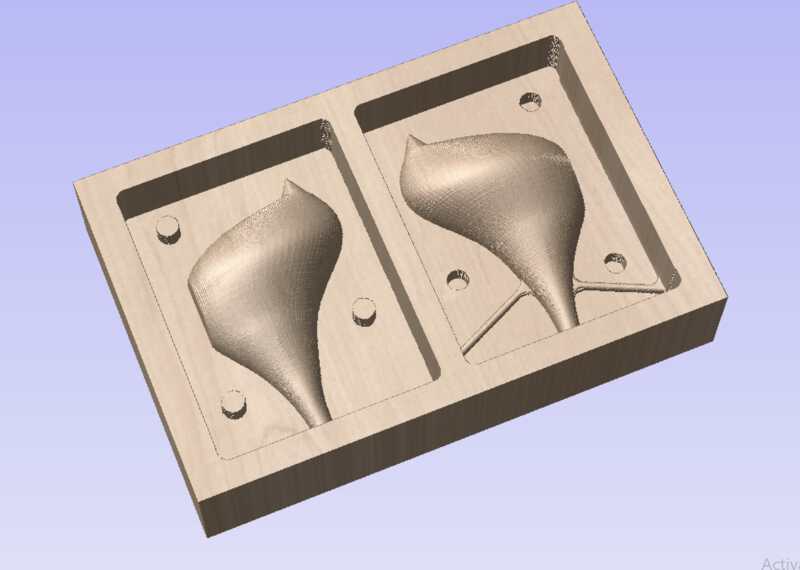 The result of the finishing toolpath simulation. The stepover of 0.5mm gives a smooth surface
Do try this at home
I wanted to test the new desktop cnc that I bought from last years student Loes . I had only assembled it, but never found time to do an actual testrun. Although I bought it to mill pcb boards, milling a wax block seemed like a good start to get to know the machine, a 3018 CNC.
So during the weekend, before I started milling on the Shopbot, I went through the motions at home.
I used a used wax block that was harmed in another process. I could not be picky about the wax blocks, as it had to fit in the 40mm z-range of this little printer. But I found a block with a height of 32mm and a useable area of 99x95mm
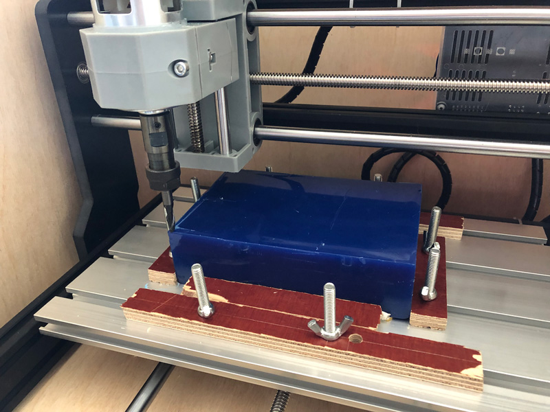 how I attached the wax to the baseplate of the mill
I plan to use a flat 5mm 2 flute endmill for the roughing path, and a ballhead 4mm 2 flute endmill for the finishing path.
gcode sender
For the software that sends the gcode to the machine, I found OpenBuilder Control. I connected my laptop with a usb cable to the controller board of the 3018 mill, opened up OpenBuilder Control, selected the correct usb port and tested if I could move the millhead around. Succes!
I then proceed to job-zero the mill to the lower left corner of the material. Since the wax thickness is almost at the outer limit of the z-range, I have some troubles getting the z zero right. I can obviously not use a probe, so settle for the papersheet trick.
design
As design, I use a simple sphere
 No vents, no positioning stuff, just the shape
toolpath generator
For the toolpath gcode generator, I intend to use VCarve. It is a windows program, and since I have a M1 mac, I install a trial version of Parallels and install a trial version of VCarve. After importing the model and adding both my endmills to the inventory I set up the first roughing toolpath. However, the trial version of VCarve does not let me save the toolpath :-(
So I look for other options. I found a good overview of CNC software and tried out some other programs. Easel did not seem to work for me, I could not find a way to import my .stl design. OpenBuilds has an online GCode Generator, but it would only import .dxf files and it did not understand the .dxf file that Fusion360 generated. In the end I settled for a trial version of MeshCam
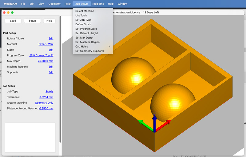 MeshCam interface
It has the advantage of having the actual 3018 as a machine profile. After importing and orienting my design I follow the steps under the Job Setup as far as I understand them, using this youtube tutorial as a guide. And then I have finally a rouging toolpath ready.
I load it in OpenBuilds Control and send it to the mill. I use the “Check Size” option first to see what the mill thinks is the working area. It takes a few times going back and forth between MeshCam and the mill, to get the orientation and program zero right. At first the endmill goes royally out of the wax boundaries, and even hits the screws.
I find that MeshCam adds a distance around the geometry by default, but since I already have that distance in my design I have to turn that off. Now the machine stays within the wax boundaries.
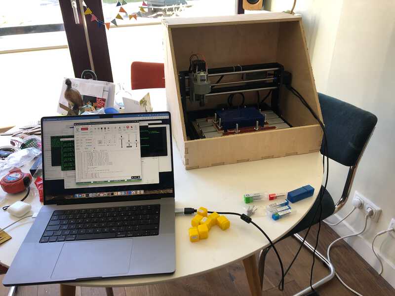
I start the job, and the machine starts to mill. OpenBuilds Control informs me that this job will take 2,5 hours. I take this for granted and go and make dinner.
After more than two hours, the mill is still at it. It has produced an enormous amount of wax scrapings, and I am happy that I made an enclosure for this cnc mill during the make something big week
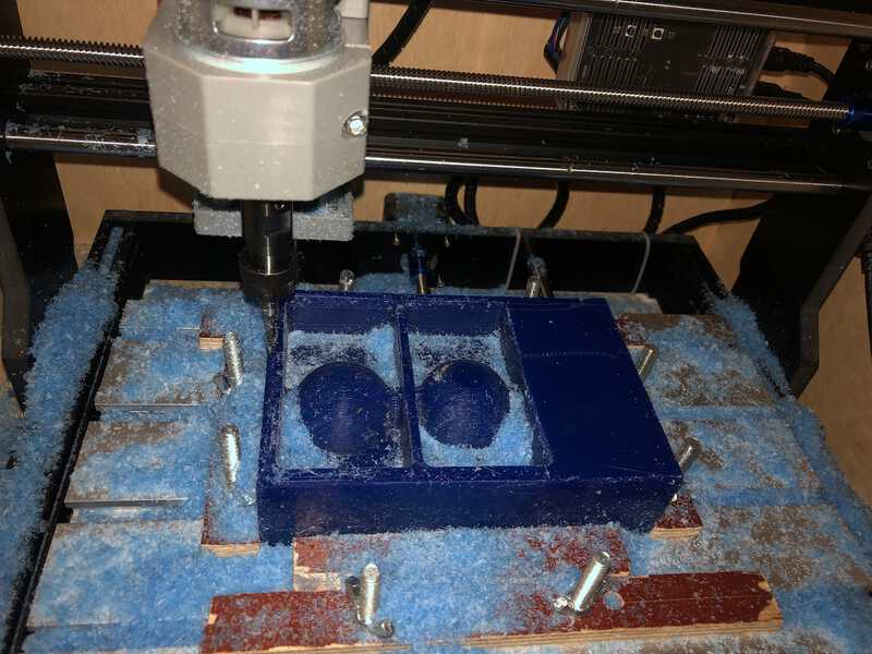
After a good 3 hours of milling, the machine is finally done. The end result is not bad at all, I think.
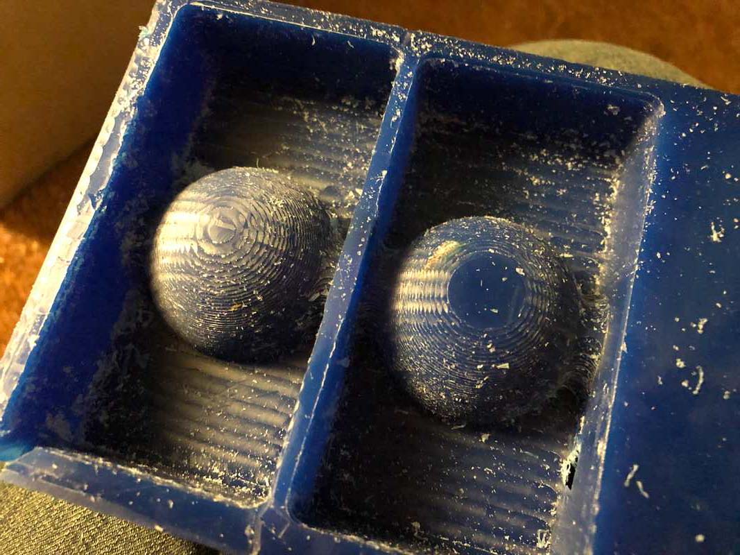
When I try to start the finishing job however, I find that the machine does not correctly return to its job zero. The endmill does not follow the original path even close, and so the finishing totally misses touch. So I leave it at that.
Even though I made a couple of mistakes and my end result is not really useable, I did enjoy this process of figuring out my own mill. I learned a lot by doing it, and it also helped me understand better all the steps that I need to take with the big ShopBot.
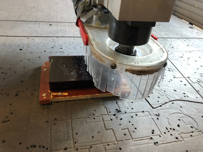
CNC Milling with ShopBot
Next day I went to Waag to try my luck on the big machine, the ShopBot.
Henk showed us the week before how to use the Shopbot for 3D milling. The process is mostly the same as last weeks 2D/2.5D milling, with the following exceptions:
- We will use machinable wax as material. This is a hard wax that does not melt easily and can be milled
- We will not use the dust extractor. We do not want to have the machinable wax in the dust collector, because it is reusable.
- We will not mill at 18.000rpm, but at 6000rpm
- We will z-level the machine to the top of the material. Since we will not mil through the material, the sacrificial layer is not in danger.
I attach the machinable wax to the sacrifical layer with a combination of double sided tape and some woodstrips. I make sure the short side of the material goes along the long x-axis and the long side of the material follows the short y-axis of the machine.
Then I take the mandatory steps to set up the machine:
- turn the machine on
- turn the shopbot software on
- install the 5mm bit that I want to use
- home the machine to its x,y position
- set the job x,y zero to the lower right corner of the material
- set the job z position
- load the first roughing toolpath
- set the spindle speed to 6000rpm
- turn on the spindle
- start the job
I was happy to see the first passes of the millhead going in the right direction.
Milling went without problems. After the rough toolpath, I loaded and started the finishing toolpath, and after some waiting, my wax mould was ready.
I made one mistake though: my walls were not high enough, or my model was not low enough. I thought that I had accounted for this in my design, but apparantly not enough. So I had some adjusting to do.
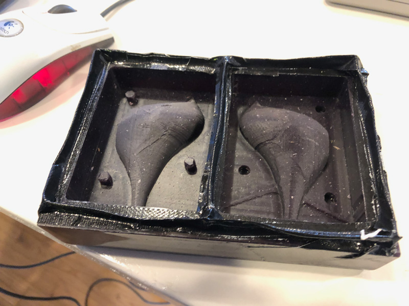 I fixed it with duct tape
Now I was ready for casting
Negative mould
casting with Oomoo
After all the good things I heard about Oomoo (not hazardous) this was the first material I wanted to try. I used Oomoo 25, which has a relaxed pot life of 25 minutes and a cure time of 75 minutes. I can use it with the basic security precautions (well ventilated room, gloves, long sleeves, eye protection)
I measure the amount needed by filling my wax mould with water and pouring that in a cup. Oomoo is a dual component material, with a (volume) ratio of 1:1. I need equal volume amounts of both A and B. I take two cups, and add half of the total needed volume of A in one cup. I stir well. Then I add half of the total needed volume of B in the other cup and stir again. I then add A to B and stir for a good three minutes. Then I pour the Oomoo into my wax mould.
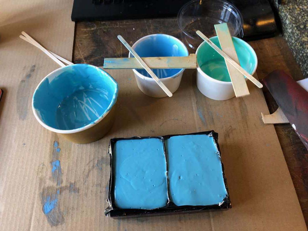
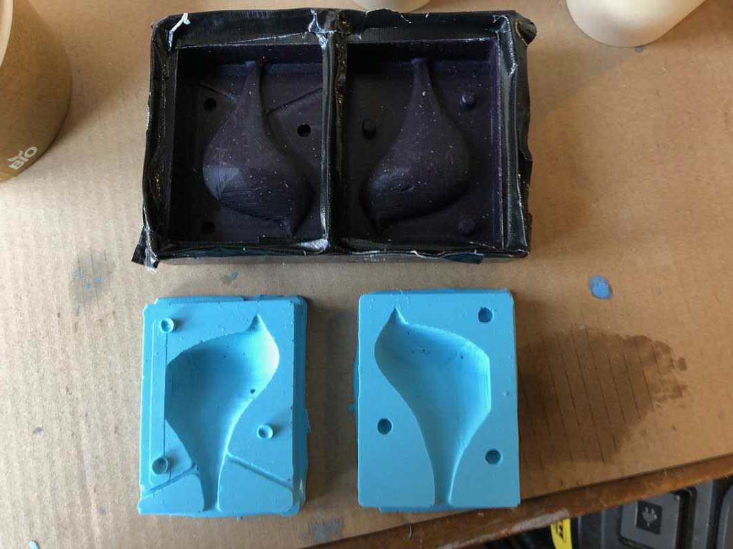
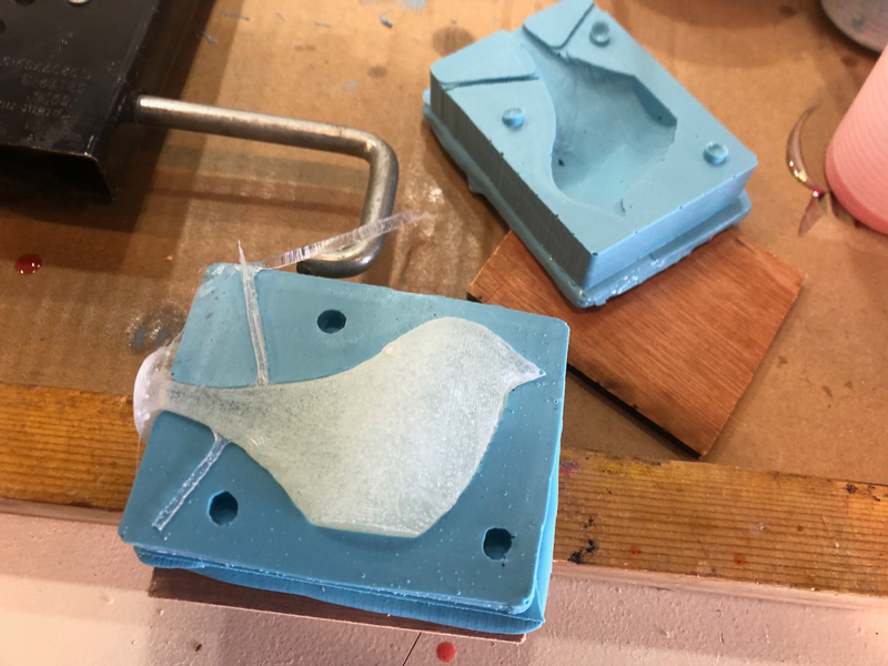
After waiting a good 2 hours (longer than 75 minutes, just to be sure) I pry my new mould from the wax mould. Apart from a few air bubbles, not bad at all.
Final cast
Now that my negative mould is ready I can finally cast my bird.
casting with Smooth-cast 325 EU
First material I use is Smooth Cast 325 EU. This is an Urethane resin, with a clear color. It can be coloured with pigments, but I used it in its basic clear version. It contains some hazardous chemicals, so it is best used in a enclosed space with proper air extraction and filtering.
It is a 1:1 two component material with a very low viscosity, so it is easy too pour. This is fortunate, because my mould has a narrow sprue that will be easily clogged when I use materials of high viscosity.
It has a pot life of 2.5 minutes, and a cure time of 10 minutes.
I measure the amount needed with water first. To prepare my mould, I connect both sides to each other, carefully aligning the positioning projections. I then add two wooden plates around it, and clamp them with a gluing clamp. I create a small funnel with a paper sheet, to help guide the material into the mould.
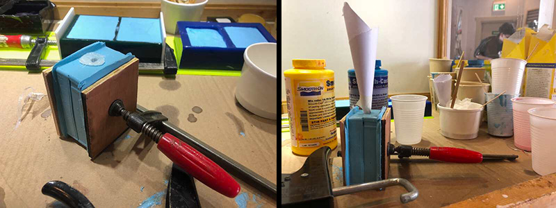
Then I basically take the same steps as with the Oomoo. I stir both components indivdually, before mixing them. Since the pot life is so short, I do not stir for too long. Then I pour the material into the funnel.
After waiting only 10 minutes, I can open the mould:
And after a little bit of cleaning up:
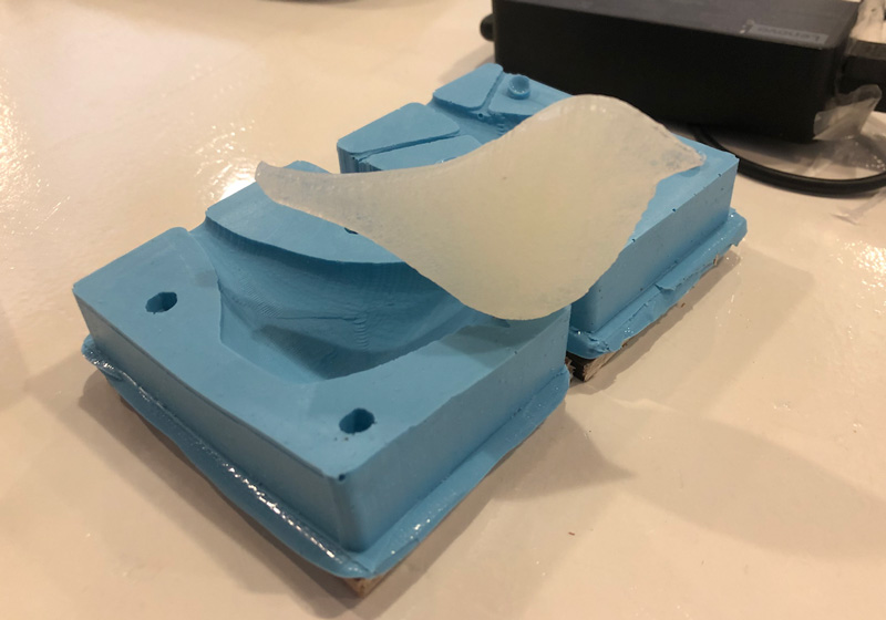 This bird went from 3D model to wax model to silicone model to its final shape in urethane resin
casting with smooth-cast 305 white
Encouraged by these succesful casts, I proceed to cast another bird, this time with Smooth Cast 305 White. This is a white liquid plastic, also with low viscosity. It has a pot life of 7 minutes and a cure time of 30 minutes.
Again, a two component 1:1 volume material, so the actions are all the same. However, after a good hour waiting, the material is not really cured. Instead it is kind of squishy, and also a bit oily. First I think that I maybe made an error in measuring the two volume amounts. But then Ben tells me that his result is basically the same.
After some online searching, I find a FAQ page from the manufacturer with the following question: “My Smooth-On plastic castings are partially cured and are exuding an oil. What is the cause?” . Although the answer points to too cold storage, I do think our casting problems are caused by the same separated B component issue.
I decide to leave the mould for now, and see if it has gotten any better in a few days. But it didn’t:
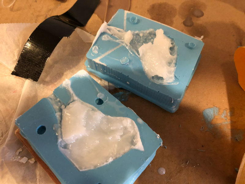 still very much liquid
casting with urethane
Since my silicone mould is occupied by the failing liquid plastic, I decide to cast another mould. This time I want to try urethane, because I want a mould that is more rigid than the silicone (oomoo) one.
I find some VytaFlex 50, a urethane rubber with a pot life of one hour and a cure time of 16 hours. For this I work together with Ben, who wants to use it for his model. We each mix a component and then add them together. This time we get a chocolate milk brown liquid with the consistency of pudding.
Because of the very long pot life, we take all the time we need. We have prepared our moulds with mould release, because this is strongly advised in the safety sheet. Apart from that, it is a more rigid material, and since I cast it in the wax mould I figure I need all the releasing help I can get.
After casting, we go home.
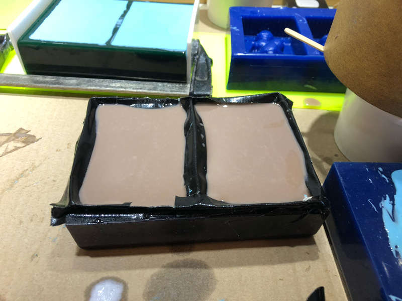
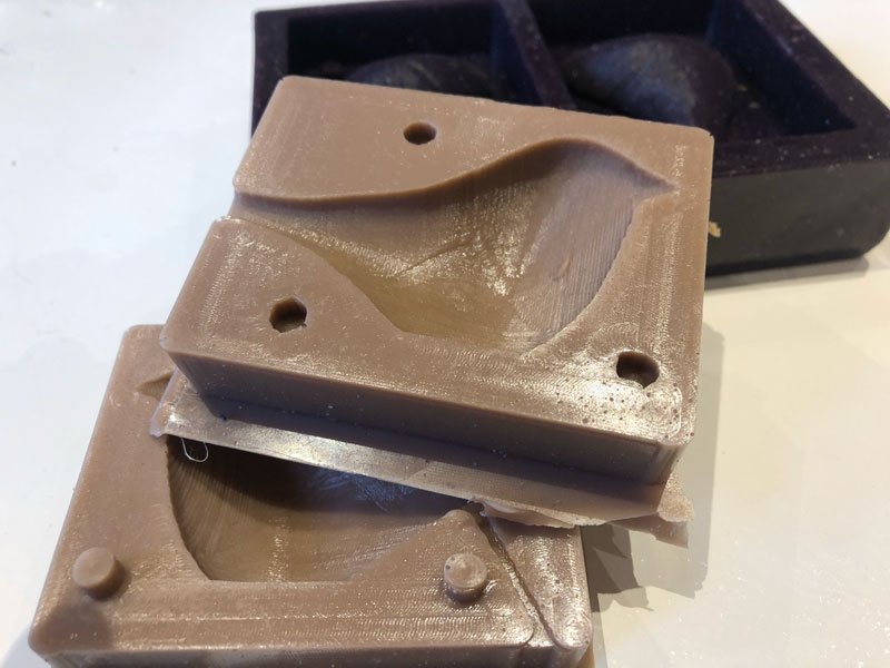
Two days later I am greeted by a very nice and sturdy mould
looking back
lessons learned
Below are some things I learned during the local and regional presentations:
https://fabacademy.org/2019/labs/dilijan/students/babken-chugaszyan/assignments/week10.html