This week we are going to work with the big lethal machine. No room for mistakes this week.
to learn / to do
Group assignment:
- Complete your lab’s safety training
- Test runout, alignment, speeds, feeds, and toolpaths for your machine
- Document your work to the group work page and reflect on your individual page what you learned
Individual project
- Make (design+mill+assemble) something big
looking ahead
what I already know
Not much.
what I want to learn
I want to learn to control this machine without making lethal mistakes.
The Big Machine
safety
Thursday morning starts with a safety intstruction. With this machine, there is no room for error. It is big and has a fast 18000rpm spinning millhead. I will repeat the safety steps in the order that Henk told them.
escape
There are two escape pathways from the room where the Shopbot is located: via the door to the Lab or via the emergency exit.
fire
In case of fire, there is a fire extinguisher next to the machine, near the side window. If that one is inaccessible, there is also one near the kitchen in the Lab.
emergency shutdown
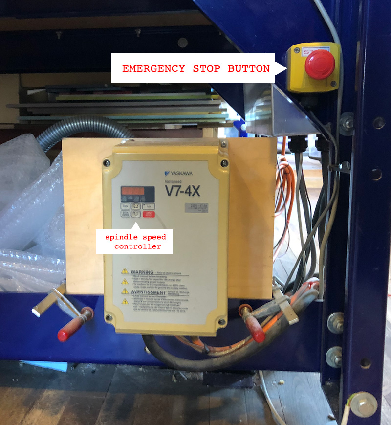
You can use the fuse box in the back of the room to cut off the power. There is also a big red STOP button on the machine. Use this only as a last resort, as it really just quits the whole job and you have to set up and calibrate the machine again after that.
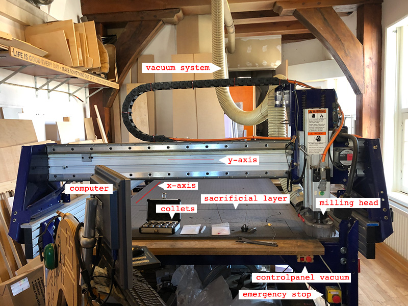
parts of the machine
There is a bridge that holds the millhead. The bridge moves the head along the Y axis and along the Z axis. The rails at the sides uses two stepper motors to move the bridge (and thus the head) along the X axis.
The head consists of a fan and a spindle. This spindle rotates with 18000 rpm.
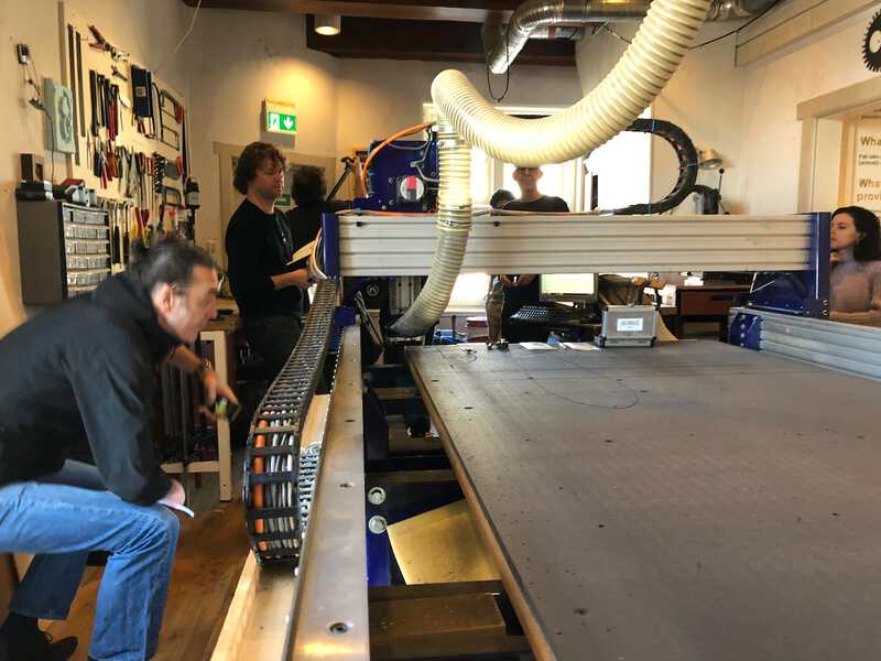
 Different parts of the machine
sacrificial layer
This machine also has a sacrificial layer. We are not supposed to mill into this.
 The sacrificial layer is the black MDF layer
vacuum / dust extractor
There is a big dust extracter that vacuums away the dust and woodchips that are produced by the milling process. This dust extractor needs to be turned on before the milling starts. The dust will be vacuumed away to a dust collector that is located in a closet in the back of the room.
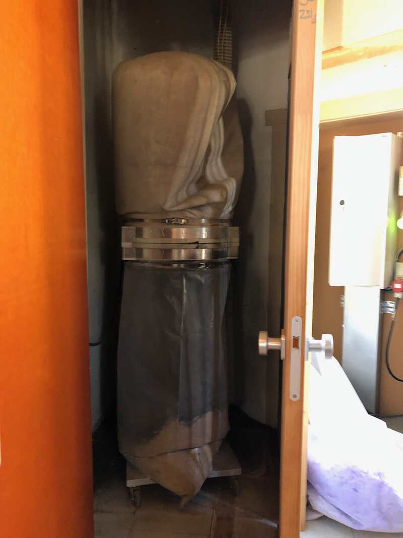 Dust collector in the back of the room
clean
Before turning on the machine, make sure:
- that everything is clean
- that there is nothing preventing the bridge to move along the rails
- that there are no rogue / left over screws in the toolpath
in case of sparks
When the bit hits a screw, there will be sparks. These sparks will be sucked into the dus extractor. Because there is a lot of sawdust collected in here, chances are that this will start a fire. Therefor, if the bit hits a screw:
2. stop the vacuum extractor with the red switch in the back of the room
3. take out the plastic bag from the dust collector
4. put your head in it and smell very carefully for any smothering signs
preparing the machine
These steps are only taken when there is a toolpath ready to be milled
mounting the tool
There are two wrenches to use when mounting the tool in the millhead. One wrench has a key attached. This is the key that turns on the spindle. This is another safety measure, that prevents the (un)mounting of the tool as long as the spindle is rotating.
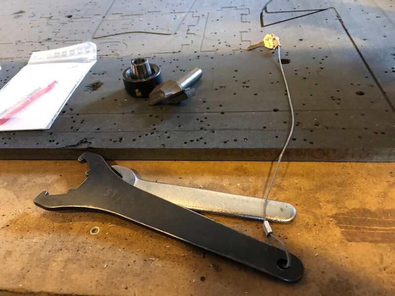 The two wrenches are connected to the key
To unmount the tool:
- unscrew the wingnut at the back of the millhead, this lowers the skirt
- use the two wrenches to unscrew the black nut/ring
- now the collet and the tool come out
- the collet can be removed from the black nut, in case the toolshaft needs a different diameter
- the tool can be removed from the collect to be replaced by another tool
To mount the tool:
- place the collet inside the black nut, make sure you hear a ‘click’
- place the tool inside the collet, make sure it touches the insides of the collet well
- screw the whole thing into the millhead, use the wrenches to tighten
- do not overtighten!
- move the skirt up and tighten with the wingnut
- the head is now ready
turning on the dust extractor
The dust extractor is turned on in three steps:
- turn on the vacuum with the red switch in the back of the room. The green light goes on
- turn on the dust extractor on the millhead with the small red button on the table.
- use the red knob on the table to turn the extractionforce up / down
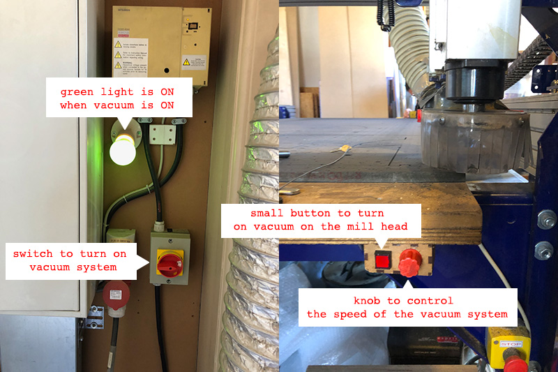 The different switches to control the dust extractor
turning on the machine
The machine itself is turned on by the big red switch at the side of the machine. The machine needs to be turned on for the software to communicate with it.
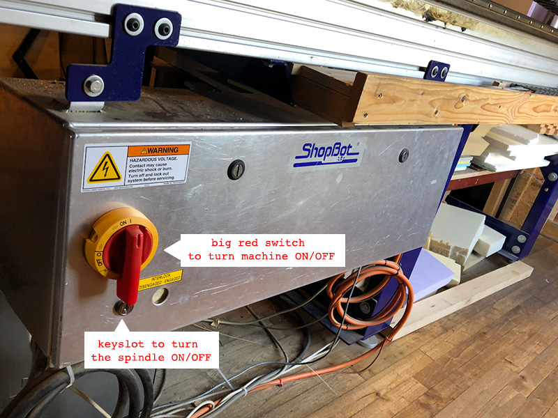 Big red switch for the machine and small keyslot for the spindle
turning on the spindle
The spindle is turned on/off by turning the key. You can set the rpm of the spindle with the knob at the bottom of the machine. Setting it to 180 means 18000 rpm, so multiply with a factor of 100
 Big red switch for the machine and small keyslot for the spindle
group assignment
the process
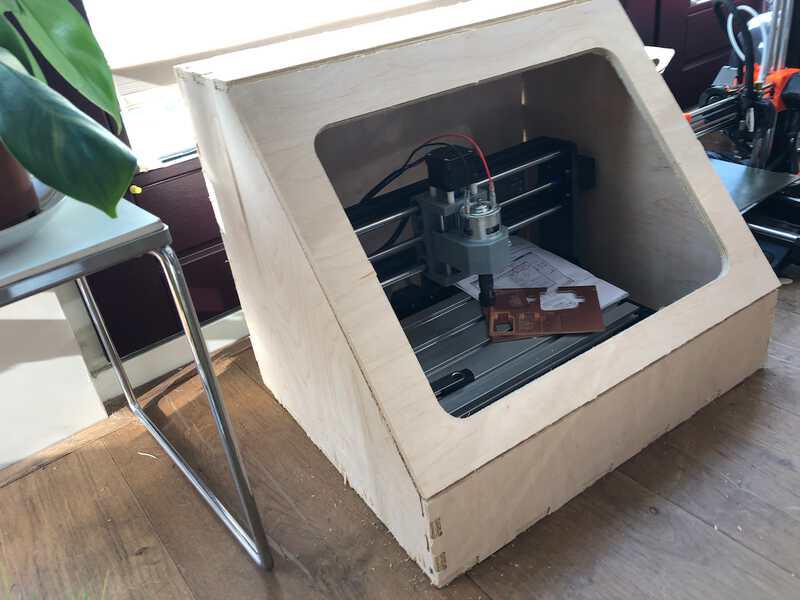
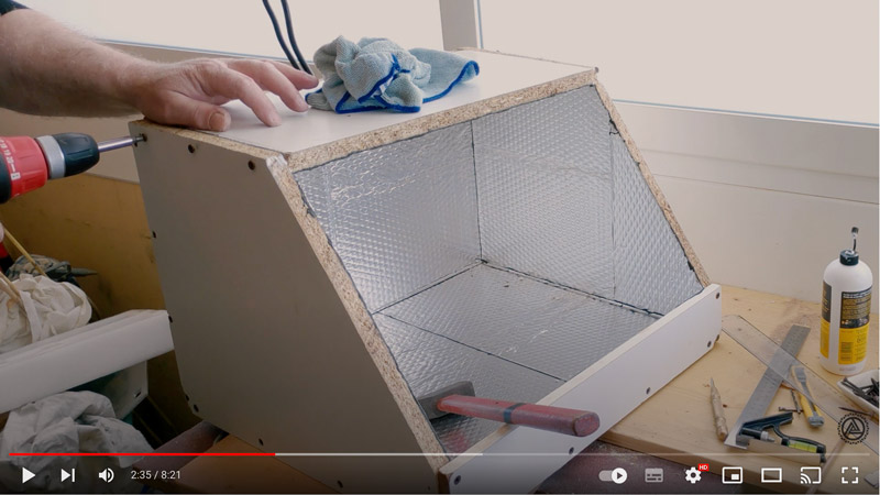
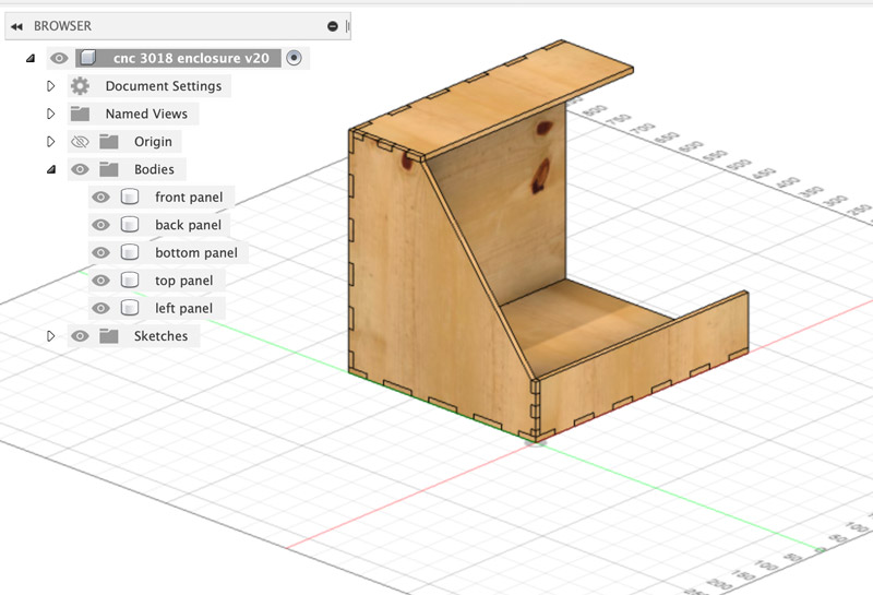
For the individual assignment I want to make an enclosure for my small 3018 CNC mill . I have seen a couple of examples, so I have a pretty good idea of what I want the enclosure to look like the one in this video but instead of screws I want to use finger joints. The material I am going to use is 9mm plywood.
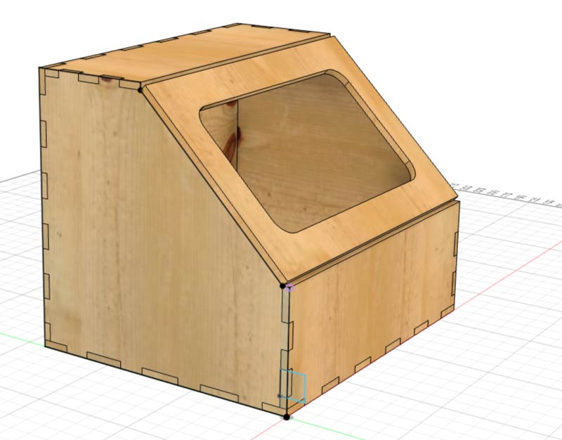
Making a design in Fusion
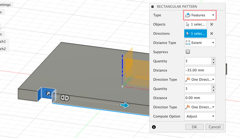
I start with taking the dimensions of my 3018CNC mill, and putting those values in the parameters of my Fusion design. Then I create the bottom panel, by creating a sketch in the horizontal plane, and draw a rectangle with the correct dimensions in it. I extrude it with the thickness of the material (9mm) and then I start to create joints. I use a tutorial for creating finger joints to get the general idea. It involves creating a sketch the size of one joint on the side of the material, extrude it inside the material to the thickness of the material (9mm ), and then using a rectangular pattern to repeat the extruded joint along the side. Make sure to set the type of the pattern to Features, to be able to select the extruded finger.
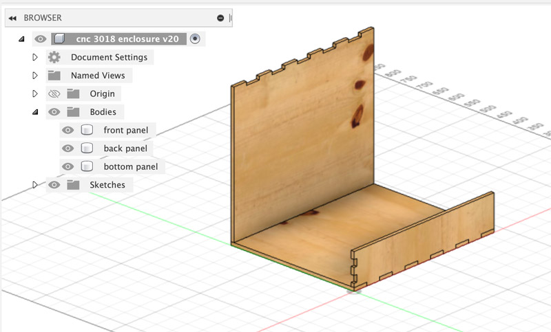
Then, on the same side of the material, I create a new sketch and draw a new panel perpendicular to it. I extrude it into the already present panel (make sure to select New Body here). Now the new panel needs to have the opposite joints. I create them by selecting the Combine tool and select the first panel as Tool Body and the second panel as Target Body. I set the operation to Cut and make sure the Keep Tools checkbox is set. Then I press OK and I have two panels that are interlocked with fingerjoints.
I proceed to build the whole enclosure this way.
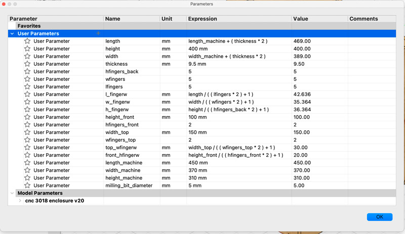
With this design in Fusion I used parameters in a more complex way, as seen in the below screenshot:
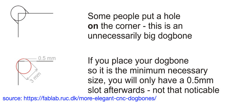
When I am happy with the design, I look for a way to add dogbones to the joints. Dogbones are needed, because the round endmill is not able to mill straight edge inner corners. The inner corner can never be more sharp than the diameter of the cutting tool. Since I am using a tool of 5mm, this will also be the diameter of the inner corner. But with a big diameter like that, my joints will not fit anymore and that is where dogbones come in. There is a good explanation about the problem here. This page also states that dogbones are usually more extreme that needed. Most people place the center of the dogbone on the corner of the material. This results in a big hole, while you only need to place the outer edge of the dogbone to the corner.
To help me creating the dogbones, I find a plugin called Nifty Dogbones I install this plugin and let it create the dogbones for me, by selecting Modify > Nifty Dogbone in the Design workspace That goes without problems. The only thing I need to remember is to run the “Update Dogbones” command when I change something in my design.
When I am happy with the design, I look for a tutorial that tells me how I can convert this 3D design into a flat design DXF file. I find one here
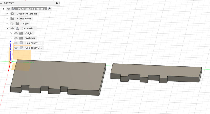
First I convert all the bodies that I want to mill to components (I ddo this by rightclicking “bodies” in the Browser and selecting “create components from bodies” ). Then I move over to the Manufacture Workspace and create a Manufacturing Model of my design. I do this by selecting the option Setup -> Create Manufacturing Model. Then I select Edit Manufacturing Model by rightclicking on the created Manufacturing Model.
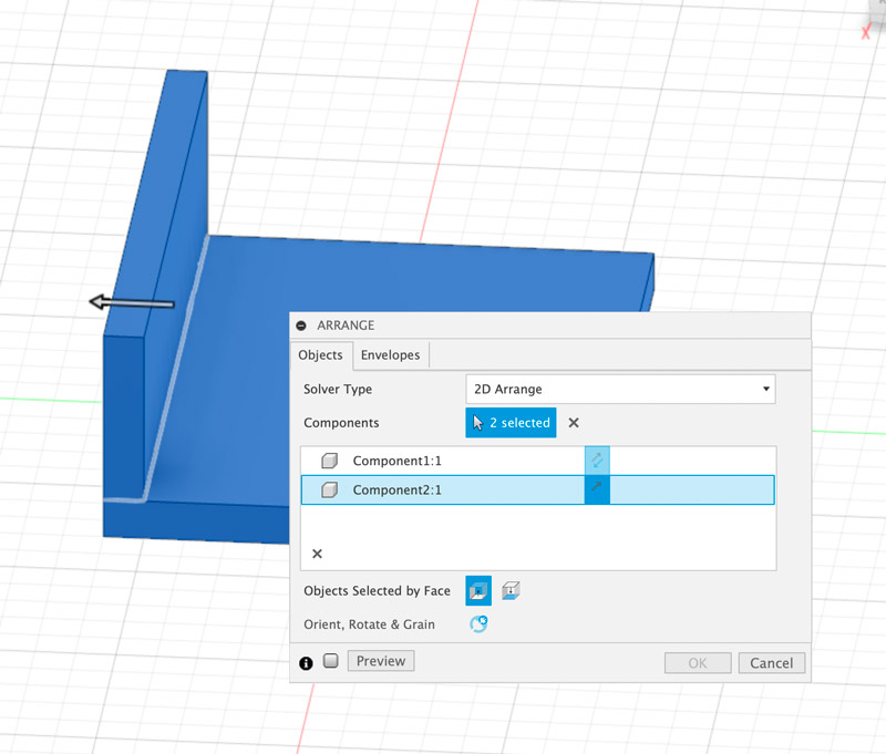
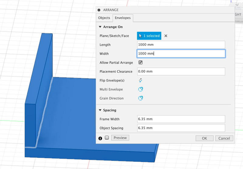
When I am in the Edit Manifacturing Model menu, I can select the option Modify -> Arrange which gives me a the Arrange panel, see the images below. I can then select all the elements that I want arranged (dragging a selection box around the object works best) and in the second panel I can select in which plane the elements will be arranged (I choose the XY plane) and what the material size is. After pressing OK all the elements will be nicely laid out in the 2D plane.
Now I need to export this arrangement to a .dxf . For this I create a sketch (again in the XY plane). Then I select Create -> Project/Include -> Project . In the Project Panel that pops up I select all the parts that I want to export and press OK. What this does is that it creates a projection of all the elements in the Sketch that I just created. When I turn of the bodies I can see these sketches as outlines.
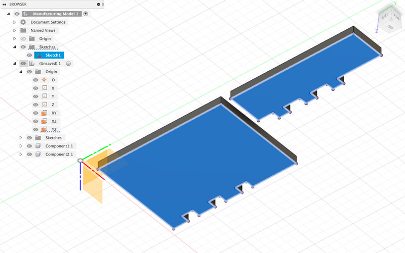
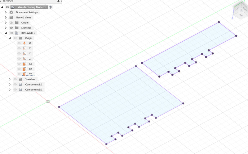
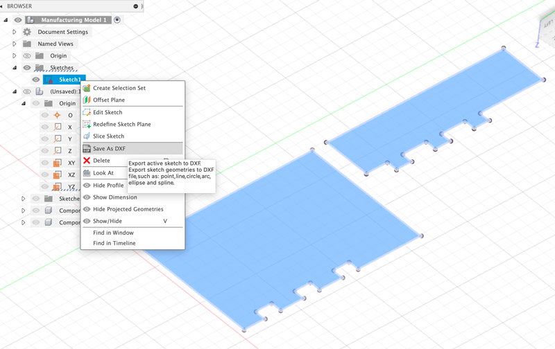
Now all I have to do is to rightclick on the new Sketch and select export to .dxf
Preparing the toolpath
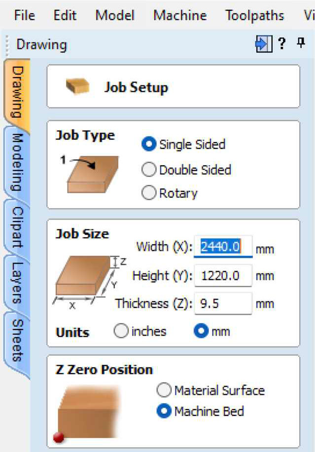
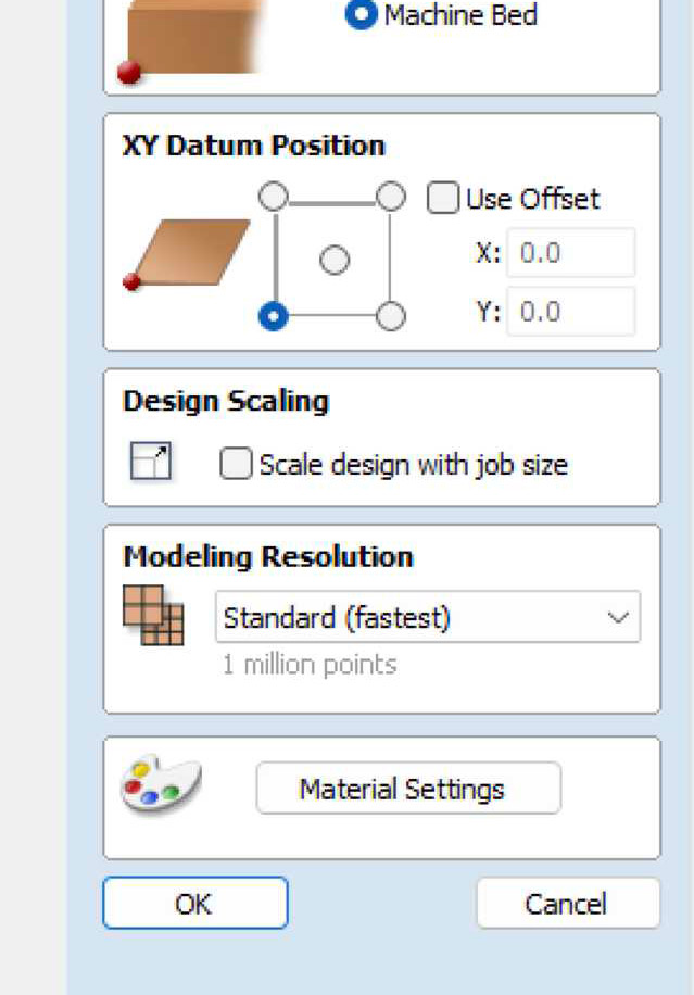
To prepare the toolpath I use VCarve. The first step in VCarve is to set up the job: the width, height and thickness of the material and the x,y location of the job (the datum position). I make sure that the units are in mm. Then I set the datum position to the lower left corner. This is the location where the switches are on the Shopbot. For width and height I use the sizes of the plywood sheet that I have, which are 2440mm x 1220mm.
For the width I use the long side of the design (2440mm) , and for the height I use the short side (1220mm mm). This is because the Shopbot at Waag has its x-axis along the long side of the machine.
I set the width of the material to 9.5 . It is sold as 9mm, but I measured it at all sides with the below results, and 9.5 looks like a good average of this.
9.32
9.59
9.79
9.47
I set the Z-position to be on the bottom of the material. This is a new trick from Henk, to protect the sacrificial layer.
Then I press OK to import the .dxf design that I exported from Fusion.
First I add 5mm screw holes around the design. I will use these to mill 1mm deep pockets so that I know where I can safely screw the material on to the bed, without the risk of the millhead running into a screw.
I also have some cleaning up to do. Not all vectors in my design are connected properly. I fix this with the Join Vectors tool in VCarve.
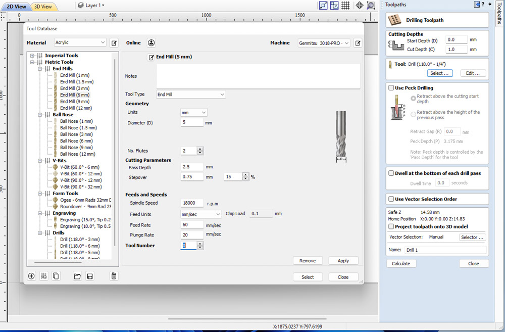
Then it is time to setup the toolpaths. First for the screw holes. For this I use a Drilling Toolpath that I set to a depth of 1mm. For the tool I select the 5mm flat 2 flute endmill that we all are going to use for this job.
I leave all other settings as is, and press calculate.
Then I am going to setup the toolpaths for all the parts. For this I use a 2D profile toolpath. I select the same endmill tool as in the Drilling toolpath.
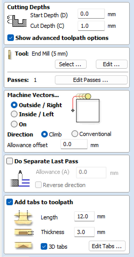
I set most toolpaths to Outside/Right, except for the inside of the window. This is an Inside/Left path. I leave the direction to Climb, as this is the default.
The pass depth of the tool is set to 2.5mm, which means that with the thickness of my material the mill needs 4 passes to get through. The feedrate is set to 60mm/sec. Without going into too much detail, this determines the horizontal speed through the material. The plunge rate (20mm/sec) is the speed at which the router bit is driven down into the material.
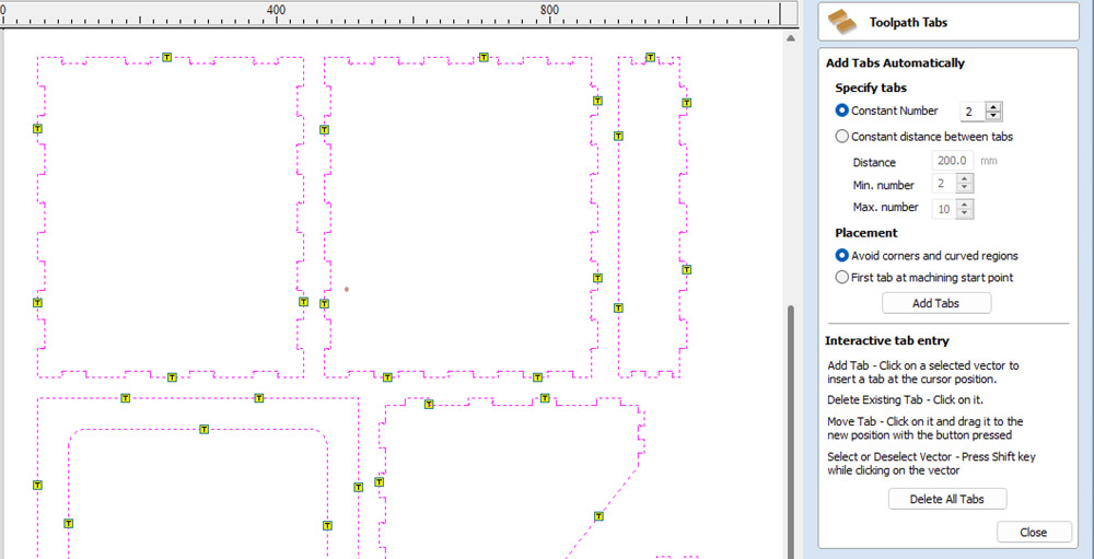
The Profile toolpath gives you the option to add tabs to it. This is neccessary because otherwise the elements will come loose during milling. The tabs make sure they stay connected to the very end. After milling you have to cut or saw these tabs to get the elements out of the sheet.
I select 3D tabs, because these are a bit faster to mill than flat tabs. I use the interactive tab entry panel because I like to set the positions of the tabs myself in area’s that I can easy sand later on.
I run a simulation of both toolpaths. They look fine to me. Then I export them and am ready for the Shopbot.

Milling on the Shopbot
I get my plywood sheet and position it on the bed of the ShopBot. I am going to drill the screw holes first, and because this is a downward motion and the material is pretty heavy I do not have to fix the material to the bed.
But first, I take the neccessary steps to setup the machine and the job:
Before turning on the machine
- I make sure that everything is clean
- I make sure that there is nothing preventing the bridge to move along the rails
- I make sure that there are no rogue / left over screws in the toolpath
steps to set up the machine
-
I turn the machine on
- The machine itself is turned on by the big red switch at the side of the machine.
- The machine needs to be turned on for the software to communicate with it.
-
I turn the shopbot software on
-
I install the bit that I want to use, a 5mm flat 2 flute end mill
-
I set the machine to its machine x,y with the button that says X/Y in the menubar
steps to set up the job
-
Then I move the spindle head to the desired start position that I have set in VCarve
- this is the lower right corner of the material, if you stand facing the horizontal bar because I have set the job zero in VCarve to the lower left corner
-
I set the x,y job zero to this position with the menu option Zero -> x,y zero
-
Then I set the job z position
- For this I need the metal plate. I Test it first against the bit to see if it makes contact.
- I Position it under the bit, on the sacrificial layer
This is because I have set the job zero in VCarve to be on the bottom of the material. Because we will mill all the way trough, this is the best way to protect the sacrificial layer - I Press the button that says Z in the menu bar
-
Then I load the toolpath
-
I turn on the spindle
-
I set the spindle speed to the desired speed
-
I turn on the vacuum
- turn it on in the back of the room with the big red button
- turn it on on the front of the machine with the red squared button
-
And start the job
Drilling goes without problems, and I use the holes to place the screws and screw the material to the sacrificial layer.
Before starting the final job, I first want to do a test job with a small part of the design, to test if the joints work and if the dogbones are big enough.
I load the toolpath, and press start again.
I keep my finger above the space bar (this will cancel the job) and to my relief I see that the head moves to the correct position and starts milling.
It starts fine, but after about the first pass of the first element, the machine starts to rattle, the horizontal bar starts to shake. I am just too late to hit the space bar and I hear a snap. Then there is silence.
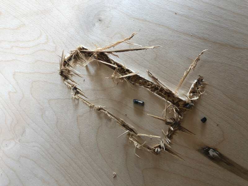
A bit shocked I inspect the crime scene. I see a big gash in the material, with some pieces of metal in it: the broken end mill. I ask Henk to help me out. He first checks my VCarve setup, suspecting I did something weird with the material thickness, but there are no problems there.
Together we conclude that when I changed the end mill, I did not tighten it enough. When milling started, this was not immediately a problem, but when the shopbot went for a second pass and moved the millhead up the endmill probably got stuck in the material and came loose. It then started to become really wobbly, causing the machine to shudder and the bit to break.
Because only a small part of the material is damaged, and I have used big enough margins in the VCarve setup, we decide to leave the material on the table, and the gcode as is and just move the head a bit to a new X,Y position. Henk helps me to set this up. It involves an unusual setting of the Z-level, showing that Henk really knows his machines.
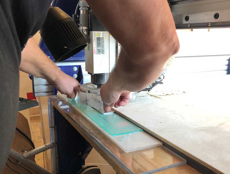
He also helps the tighten the new endmill, so we are sure it will hold this time. And then it is time to start the machine again. I bit anxious I press the right buttons. The Shopbot starts. And keeps going nicely this time. I wait until the test job is finished and try out the joints. All is fine, the joints work and are snug engough to my taste. And so I start the final job, that takes about an hour.

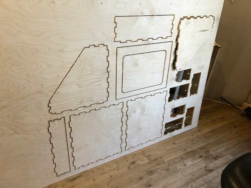
No problems here anymore. When the job is finished I unscrew the material and take it from the table. Then I take a saw and cut all the pieces loose. I still have to sand it, but this is how the final result looks when assembled.

looking back
what went wrong, what went well
Well, apart from the obvious thing that went wrong (and will probably haunt me for quite a while) the rest went quite well. There is one thing I did miss: the opportunity to have a pocket around the panel where I will put the acryllic sheet, to hold the sheet in place.
lessons learned
The big lesson learned is to really really tighten the endmill when using the shopbot. Also learned: take your time. Everything involving working with the Shopbot takes more time than you think. Preparing the toolpath in VCarve will lead to some a-ha moments that make you want to change your design in Fusion. Preparing the Shopbot takes time. Securing the material to the mill bed takes time. Waiting until the Shopbot has finished takes time. It is best not to rush any of these steps and to mentally reserve a whole day for the job.