Lasercutting and vinylcutting. I am looking forward to this, because I want to make an inlay box for the board game Agricola since forever. I think the lasercutter is something I can use for this.
to learn / to do
-
Group assignment:
- characterize your lasercutter’s focus, power, speed, rate, kerf, and joint clearance
- Document your work to the group work page and reflect on your individual page what you learned
-
Individual assignments:
- Design, lasercut, and document a parametric press-fit construction kit, which can be assembled in multiple ways. Account for the lasercutter kerf.
- Cut something on the vinylcutter
looking ahead
what I already know
Not much. Maybe nothing. I know a bit about parametric design, but only since last week. I understand the concept, I did the tutorials, but I know that is not the same as being able to apply it all by yourself.
what I want to learn
To keep it simple. Start simple, build it up during the week, instead of aiming for the beautiful end result that is already in my head.
My ultimate goal is to use the lasercutter to create an inlay box for the game Agricola with different boxes for all the elements and the cards. But I think it might be to big a stretch, so I will focus on making parts of it instead.
lasercutting
machinery
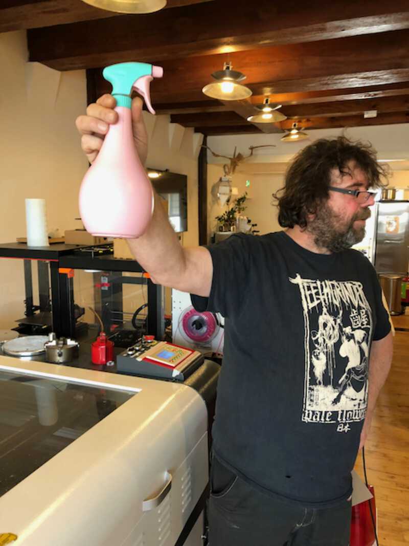
The lasercutter at Waag is from brmlasers.com . It is more than 10 years old, but it is big and sturdy. Henk has replaced the controller last year, which greatly enhanced its capabilities. It can now work with recent fileformats and is also much easier to configure. Henk also replaced the electronics of the machine, and the software that directs the controller.
But how does this all work anyway?
The lasercutter consists of several machines that work together. There is the lasercutter itself. But there is also a water chiller, fume extractor, compressor and a computer involved
lasercutter
In essence, the lasercutter machine consists of a flat bed, two axes and a laserhead. The two axes give it its horizontal and vertical movement. The horizontal bed is where the material to be cutted goes. The laserhead is fixed to the horizontal axis and points down to the material. The laserhead does not hold the laser! This was something I never thought about, but it only consists of a lens and a mirror. The mirror is pointed to another mirror at the end of the axis that it is fixed to. That mirror points to a mirror at the end of the vertical axis. And thát mirror points at the actual laser.
The laser itself is a big tube behind the machine. It is watercooled by coils that run around it, because it gets pretty hot. When the laser is turned on, it sends a laserbeam to the first mirror, and that gets reflected to the second mirror and eventually ends up at the mirror in the laserhead. That mirror sends the laserbeam down through the lens where it gets focussed on the material.
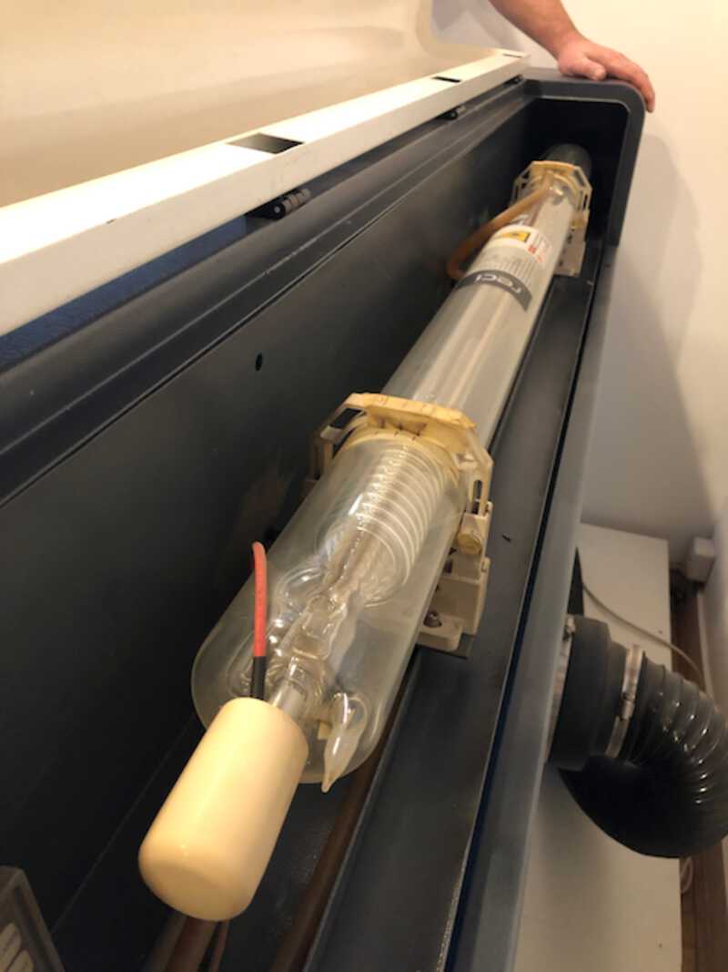
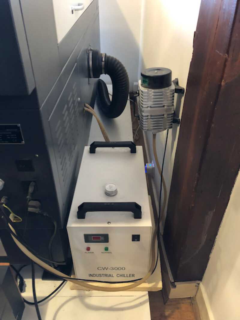
Also behind the machine is the waterchiller, to cool the laser, and a compressor that sends compressed air to the laserhead to keep the material there from burning.
Because lasercutting gives quite a lot of harmful fumes, the laserbed and the laserhead are contained in a big chamber to hold in the fumes. To get rid of the fumes, there is a fume extractor. It is connected to a big pipe that comes out of the back of the machine. The fume extractor has two filters two clean the air that comes out of the lasercutter: a hepa filter and a fine dust filter. It is a bit noisy, just like my extractor hood at home. So you only turn it on when you are actually cutting.
computer
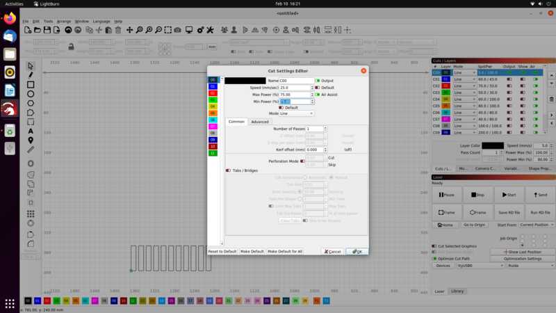
The computer controls the lasercutter. It runs LightBurn, the software that we can use to feed it the designs that you want to be cutted, and also to set the parameters for the process. Most important in this are speed and power. Generally, more speed is better. It results in less burns on the backside of the material and also makes the whole process a lot faster which means less waiting until the lasrcutter is done. Less speed gives you a better and more precise cut.
Power determines the force of the laserbeam. With more speed, you need more power as the time the time that the laserbeam touches the surface is shorter than with a lower speed.
Below is a screenshot of LightBurn and the panel that lets you set speed and power.
safety
The laser is not to be left alone while running. Because of the fumes, the fume extracter needs to be turned on while the laser is cutting. It is also best to leave it running for a full minute after it is done lasering.
In case of fire in the laser chamber:
- turn off the laser with the red stop button.
- turn off the fume extractor
- let the fire die out because of oxygen starvation
- or, when it is small enough, use the special quick fire extinguish device
cleaning
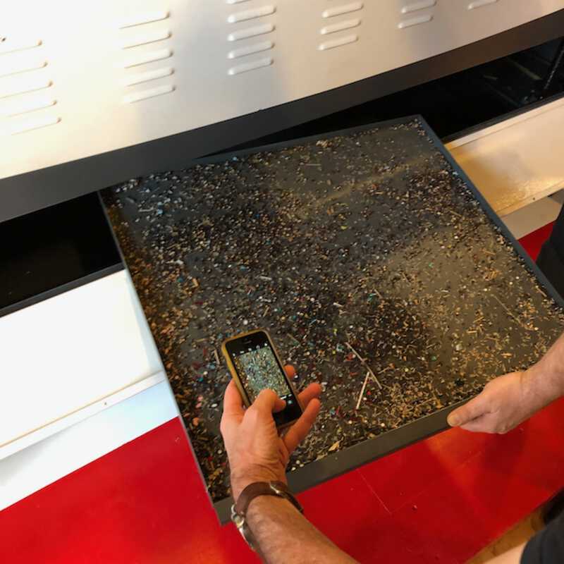
The lense and mirror of the laserhead need to be occasionally cleaned. Although this is not something we are suposed to do ourselves, Henk has showed us how it works. Most important part is to put the lens back in the correct way, which is with the flat side up (otherwise it will not focus the beam but spread it). There is also an ashtray inside the machine, below the bed where the bigger particles fall in. That needs to be cleaned occasionally as well.
workflow
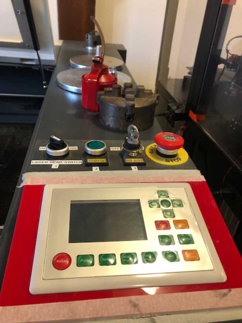
To start lasercutting, the following steps should be taken:
- Turn on the machine, with the switch marked 1 and the button marked 2. Leave the laserhead marked 3 off for now.
- Turn on the computer, so that the laserhead can be controlled.
- Place the material on the bed and position the laserhead above it
- z-level the laserhead. You do this by hand with the wooden z-level tool. Screw the dark ring around the laserhead loose and move it up/down untill it rests on the wooden tool
- Load the design into LightBurn, check the location of the start position and do a ‘dry run’
- When everything is set up correctly, it is time to turn on the vacuum extractor
- Then turn on the laserhead (marked with the number 3)
- Start the job
the group assignment
measuring the kerf of the laser
This was a group project. I worked together with Benjamin for this.
To calculate the kerf, we wanted to have the laser cut out 10 strips of 10mm each. Then measure the width of these 10 strips combined and subtract that value from 100 and divide it by 10. That would give us a more precise result that just cutting one strip and measuring that.
To create a design for the printer to use we used OpenSCAD. This was Benjamins idea, and it worked really well. Because it was just a repetition of the same strip, we could use a square() and a loop and some transforms. We had a working design pretty quick:
for(i = [0 : 1 : 10]){
    offset = i * 15;
    translate([offset,0,0]){
        square([10,50]);
    }
}
that resulted in this design:
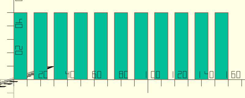
We exported the design to .svg , saved it on a usb stick and transferred it to the computer that controlled the lasercutter. There we imported it into Lightburn.
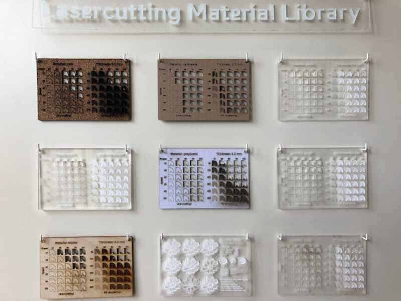
We wanted to measure the kerf for 2.1mm acrylic . We estimated the speed and power necessary to cut through this material. For this we used the “Lasercutter Material Library” next to the laserprinter that has a bunch of testruns with different speed and power values on different materials.
We ended up with these settings:
speed: 25 power: 75
That worked great! We had a whole bunch of 10mm strips in a matter of seconds. We placed them next to each other and started measuring. That’s weird, the total width of the strips was more than 10cm.
Turned out we had 11 strips! A classic programmers mistake.
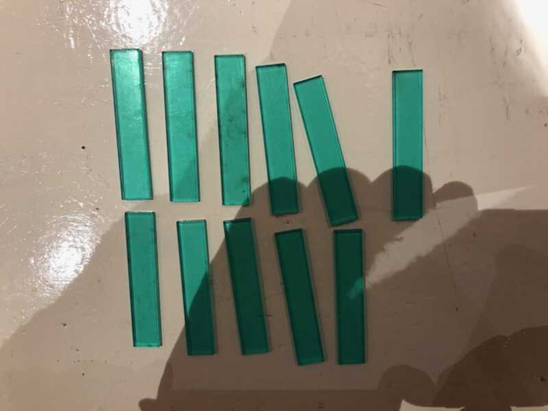
After tossing of of the strips we ended up with a total width of 97.69
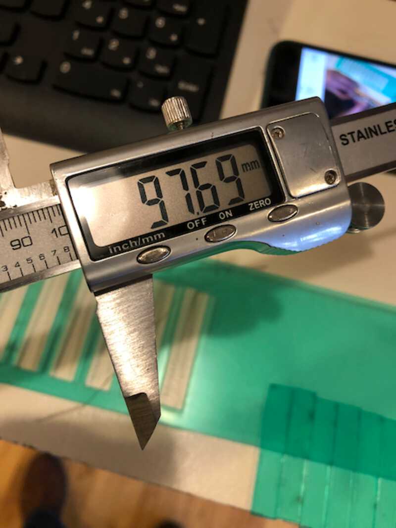
and we calculated a kerf of 0,23
creating a slot calibrator
Next step was to cut out two “slot calibrator cards”. These cards look a bit like a comb. They have slots that decrease in size by small increments. You use these two cards to select the best slot size for your press fit joints. The slot size that results in a snug fit without breaking or bending anything is the optimal size.
Again, we used OpenScad. This time, the script was a bit more complex, as we had to use difference() to subtract the slots from the card:
difference(){
   square([110,40]);
   teeth();
}

module teeth(){
    cutout_offset = 0.05;
    kerf = 0.07;
    thickness = 2.74;
    expected_cutout = thickness - kerf;
    initial_cutout = expected_cutout - (cutout_offset * 5);

    for(i = [1 : 1 : 10]){
        offset = i * 10;
        actual_cutout = initial_cutout + cutout_offset * i;
        translate([offset,0,0]){
            square([actual_cutout,25]);
            label(str(actual_cutout));
        }
        echo(str(actual_cutout));
    }
}

module label(txt){
    translate([-1,28,0]){
        text(txt, size=2);
    }
}
The important parameters are:
- kerf
- thickness
With these new values, we cut the two calibrators. In testing, it looked like the gap that measured 1,91 gave the best fit for the press fit joint. This was also what we measured, with a material thickness of 2.1 and a kerf of 0.23 (2.1 - .23 = 1.87)
Upon close inspection, I saw that the acrylic was covered with a protective sheet. After peeling it away, and revealing that the acrylic was a dull transparent, the material was of course less thick. Now the best fitting gap was the gap that measured 1.81 . This also made sense, because with measuring I found to protective sheet to add a .10mm in total.
trial and error
Some useful things I found out during, by trial and error:
individual assignment
creating a parametric press fit design kit
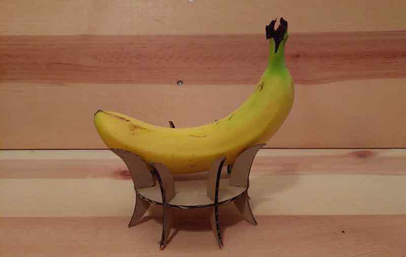
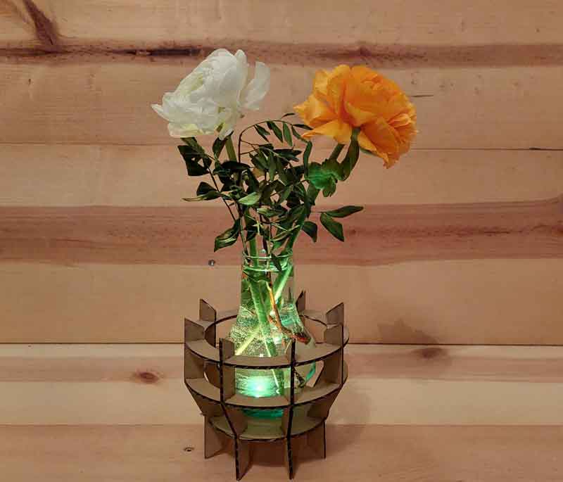
After giving it some thought, I realised that even Agricola inlay box parts were probably a bit too complex at the moment. Besides, they had no press fit joints in my ideal world. So I switched plans. I wanted to make a kind of kit to create different useful objects. Like a candlelight holder, or, probably safer, a little plant.
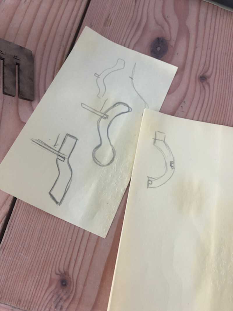
This is a first sketch of the ‘beams’ I wanted to use:
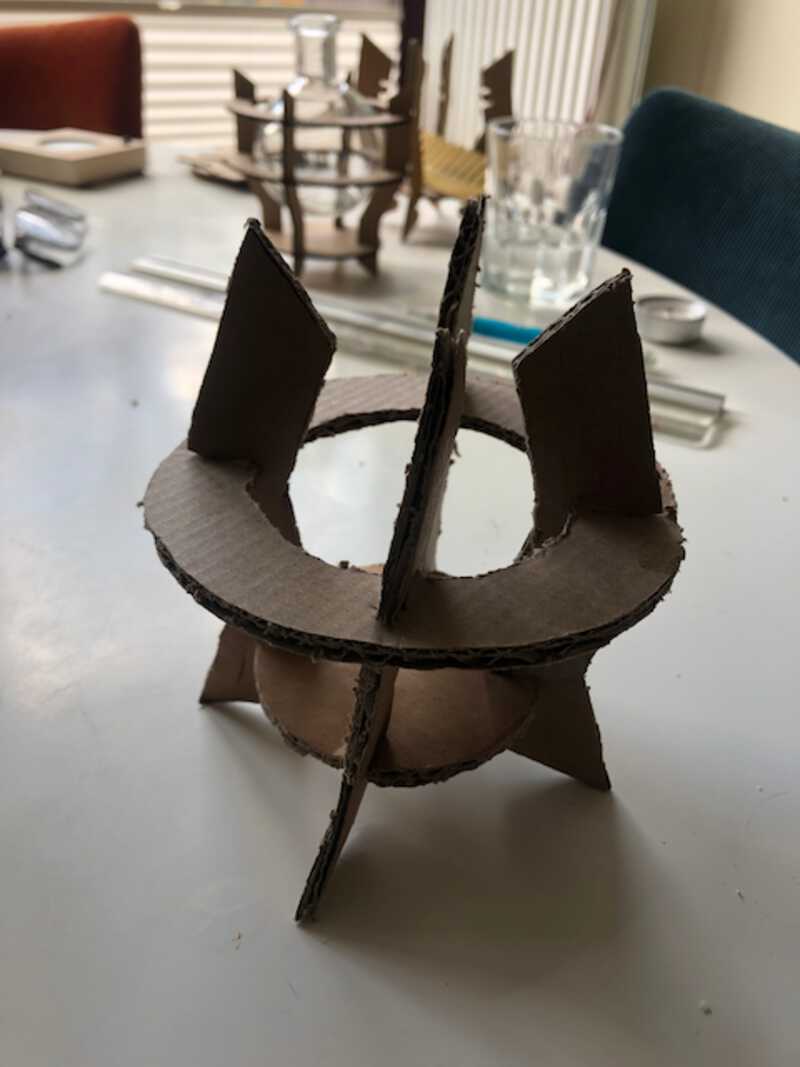
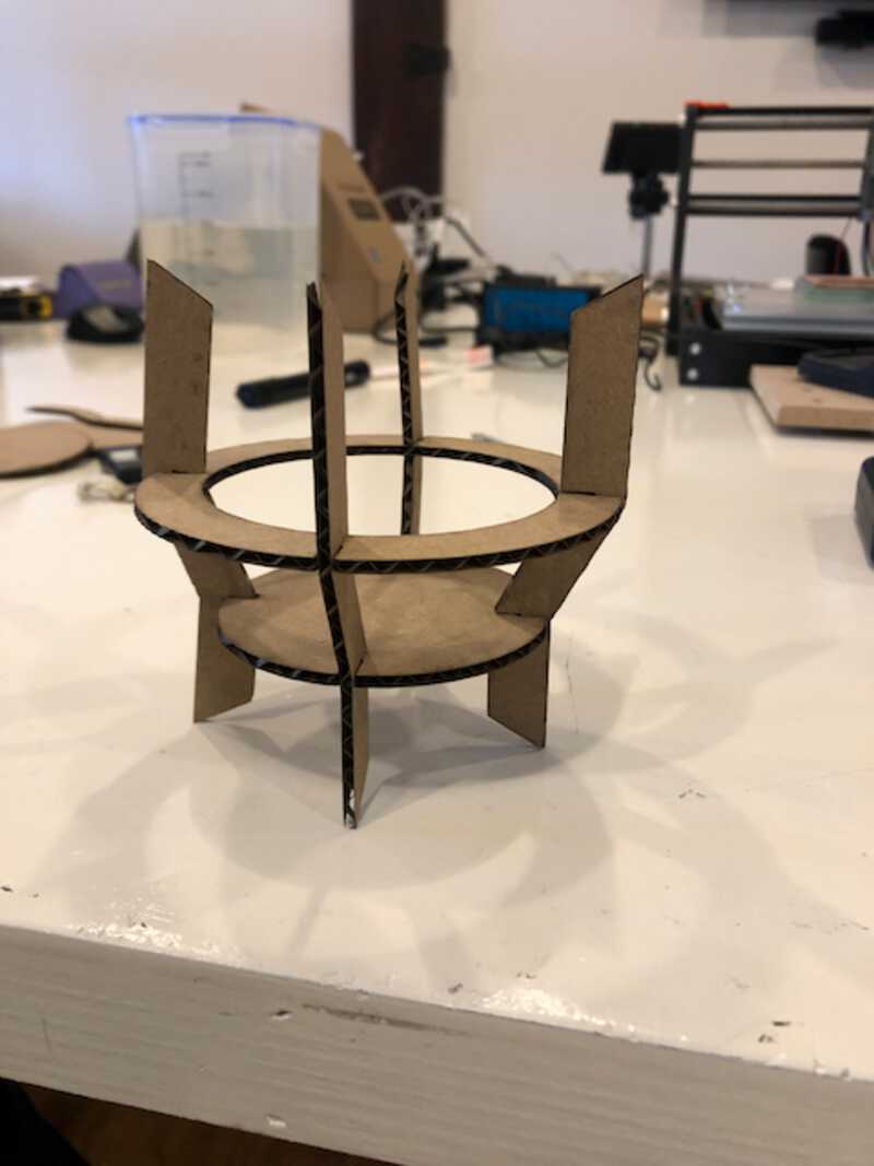
This is an early prototype in cardboard, made in the old fashioned way:
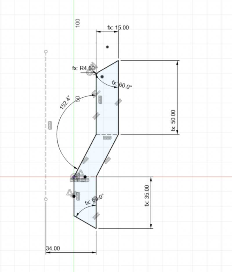
I started to draw a first shape for the beam, in Fusion360. I made it as parametric as possible, and also made sure it was properly constrained:
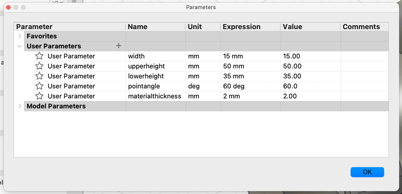
Below is a list of the parameters I used for this design. They are pretty simple still, as I still have to discover the merits of using calculations . But with this parameters, I make sure I both the top angle and the bottom angle are always the same. It is also easy to change the thickness of the material which comes in handy when testing out the pressfit slots.
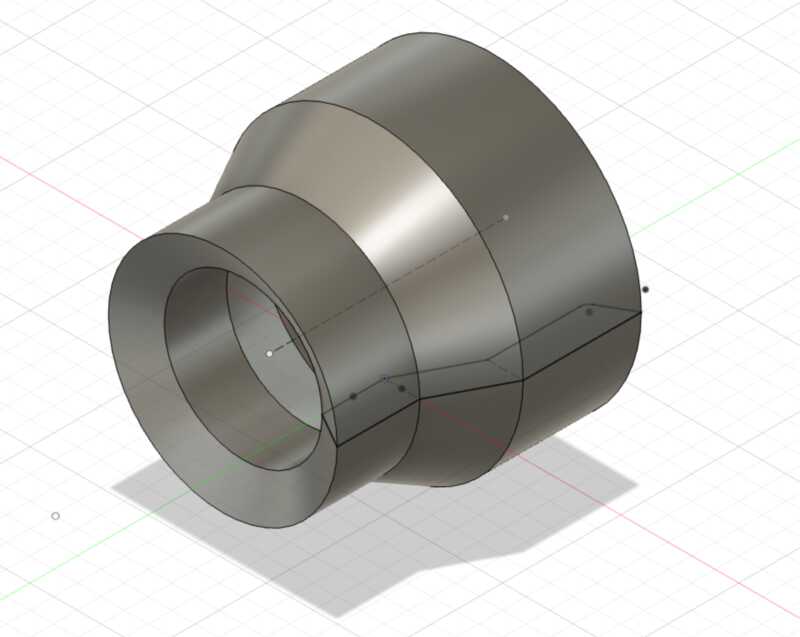
I then revolved it to a solid object, also in Fusion360 . This is because I had found about the Slicer for Fusion360, and I figured it would need a solid body.
It took a few tries in exporting it to the Slicer. Mainly because the Slicer used a different reference pane than Fusion itself. Objects drawn in the vertical plane would end up lying on their side in the Slicer. So I drew the object in the horizontal plane. That is why it is lying on its side here:
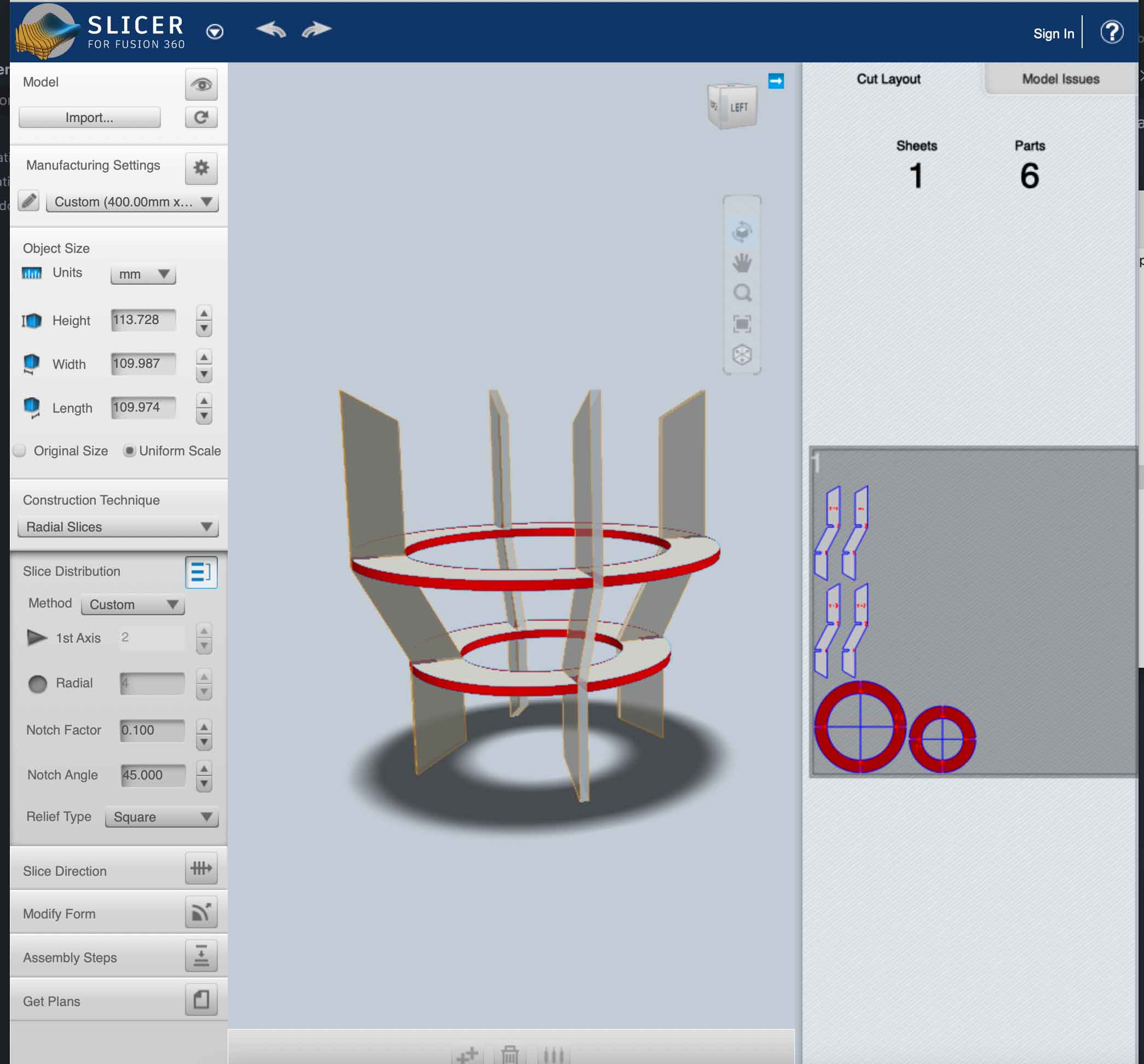
Once I exported this body to the slicer, and selected a Radial Slices, I ended up with:
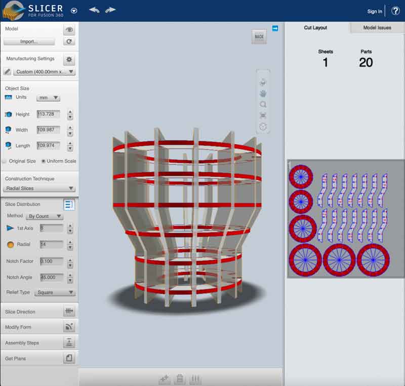
I played around with the 1st Axis and Radial settings on the left, until I had a model to my liking. On the right in the screenshot below, you can see the shapes for the lasercutter.
I exported these shapes to .eps :
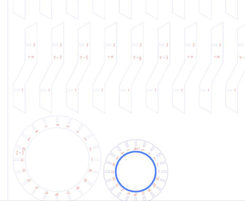
And then read them into illustrator
In Illustrator I did some ‘post processing’, like deleting the cutout circle in the smallest circle. I wanted that to be a bottom instead of just a ring.
Then it was on to the lasercutter for the real deal!
The first run failed, I did not adjust the settings that the previous user used (75,25) The second run cut ok, with 75 speed and 50 for power. But the slots were too big.
I adjusted the slotsize to the one that I had determined earlier with the calibrator: 3.13, exported the model again, tweaked it in Illustrator and went for the third run.
That went well! Later it turned out that I had used the wrong settings for the kerf: I used 0.07, but it was 0.027. I had asked it but recalled it incorrectly.
Now I had a working proof of concept, and went back to Fusion360 to make different parts
These were the adjustments I wanted to make:
- smaller baseplate circle (waxine lichtje = 38mm, + 2x15 = 38+30 = 68/2 =
- bigger baseplate circle
- different amount of cuts: 3,4, 8 (for ‘extended’ models)
- also positioned the slices better
postprocessing in Illustrator
The workflow I used, for each of the sizes was as follows:
-
First I would change the baseplate size in Fusion360
-
Then export the changed body to the Slicer
-
Adjust the slicer until I had the configuration I wanted:
- 3,4 or 8 vertical beams
- 2 or 3 horizontal slices
-
Then I exported each configuration as .eps
-
Finally I read the .eps into illustrator and copied the new shapes to one big illustrator file.
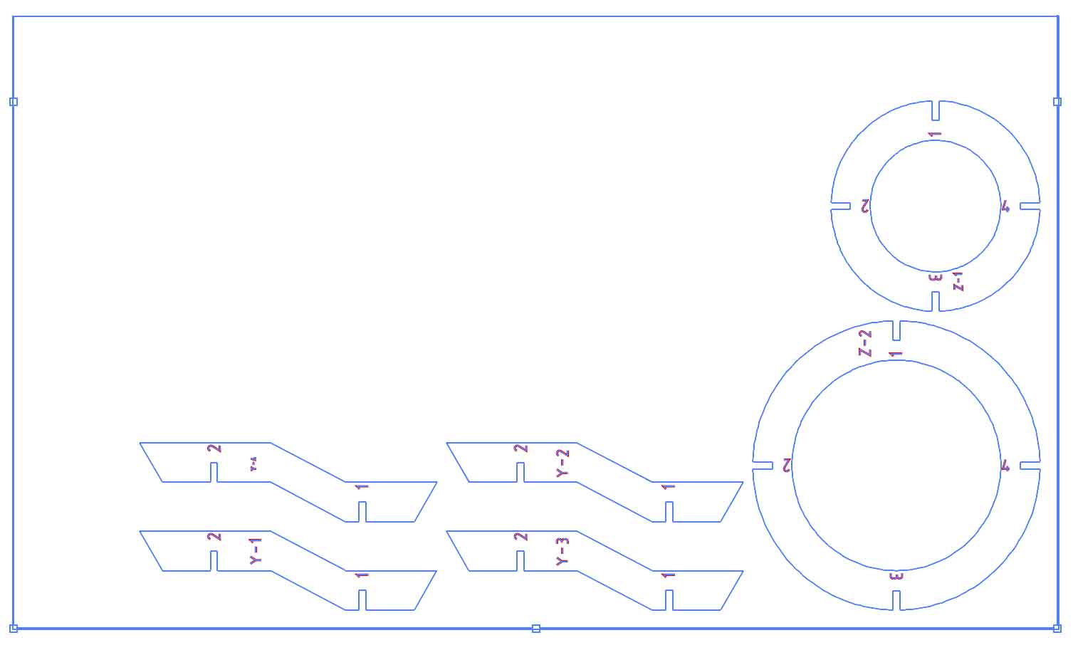
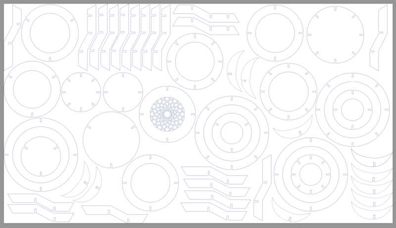
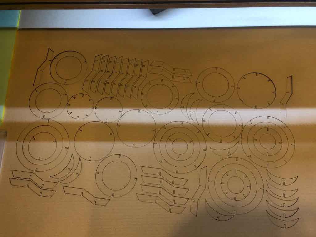
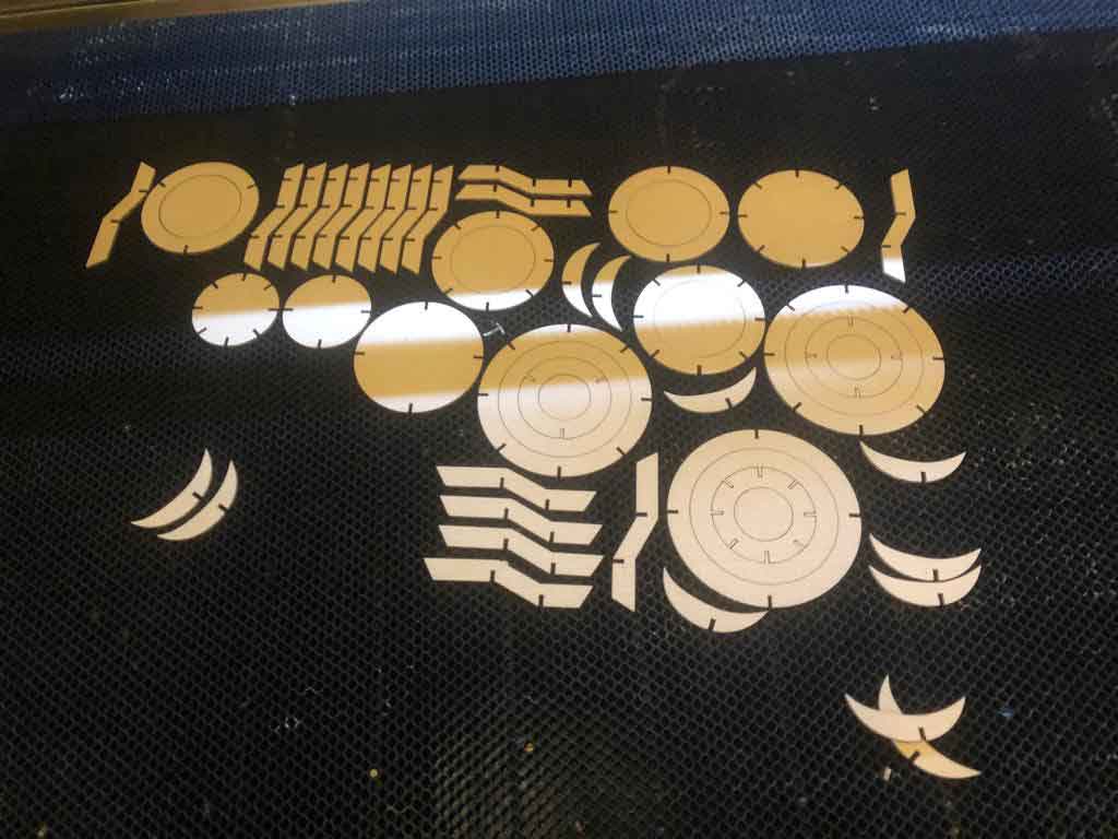
This is what I ended up with for my final run:
I realise that I could have saved a few steps, had I used a circular pattern for the slots in Fusion360 and omitting the whole Slicer exports. But this was after I viewed a presentation by Babken, and I was already well on my way with the Slicer. I made a test in Fusion360 of a parametric cog wheel, to test it all out, but kept with my own workflow.
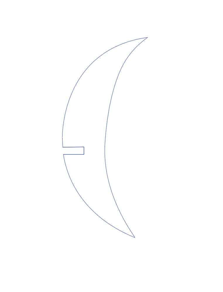
I feel needed these steps to get acquainted with getting a model in and out of the lasercutter. Especially the ‘post processing’ in Illustrator gave me a good insight in what I was actually doing here. For my final run, I also drew a free form in Illustrator:
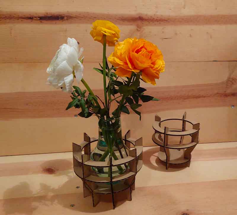
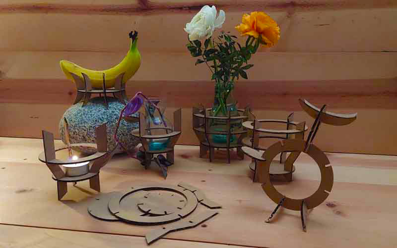
The last run with the final ‘cut’ went smooth. Before I went for the whole set of parts, I did a test run with a smaller set, just to be sure. That went fine, and so did the final run:
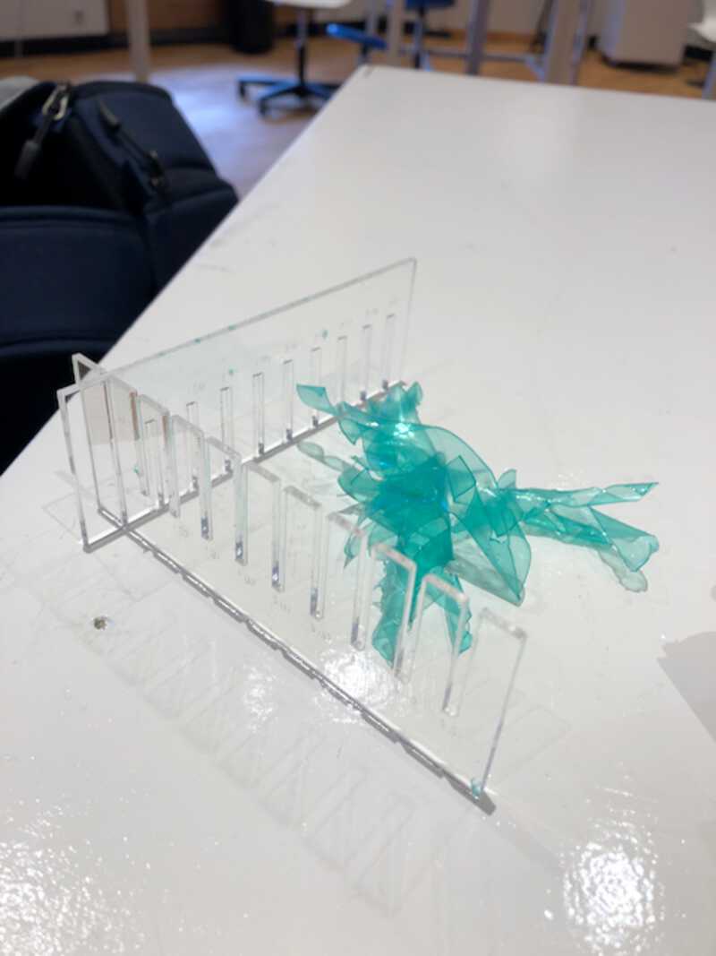
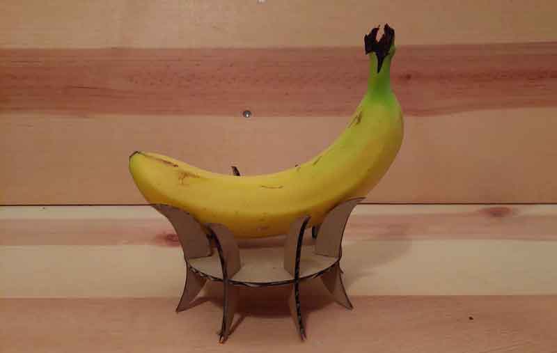
hero shots
cut something on the vinylcutter
Mods
The vinylcutter is controlled in our case by the program “Mods”. It looked a bit intimidating at first, but after working with it it turned out not too hard. You start it from the terminal with:
bash mods
which launches the mods server and a web interface where you can select the image that you want to plot. I used a cool mandala vectorized image as first, but I could not get that to work. I think because it contained lines, while the vinylplotter needs shapes.

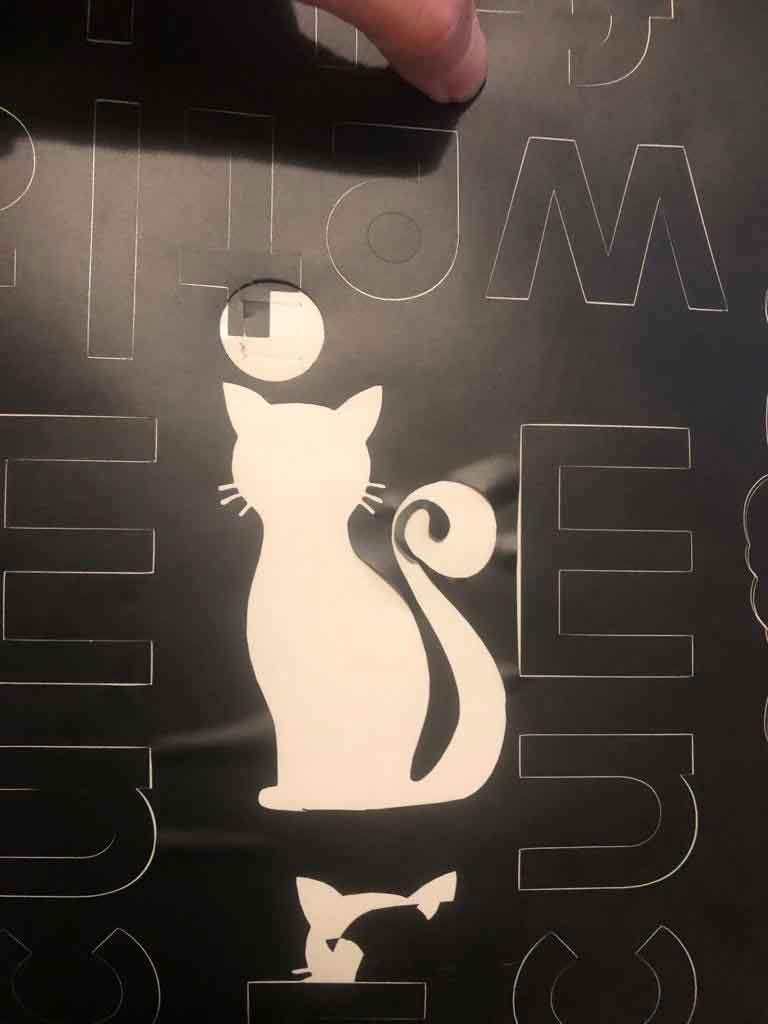
After that, I went for a simple cat image. I used a .png this time, as Mods also allows that for input. This image did work, and showed up in the last panel in Mods, signifying that it could be plotted.
I started the plotter, and it did do the movements, but did not cut anything. I checked the knife, but that was fine. So I set the pressure a bit higher, and this time the cat cut fine.
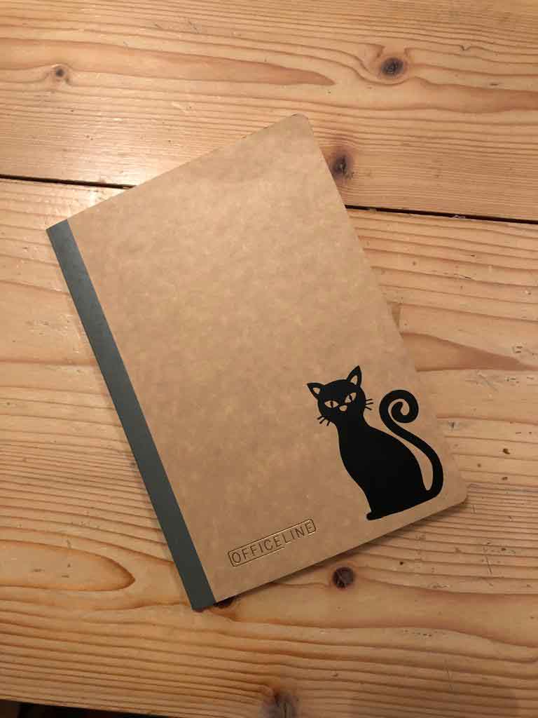
After weeding, I transfered the cat to transfer tape and transfered it to my sketch book.
looking back
what went wrong, what went well
This week I was kind of stressed out, because of my late night Blender actions in the previous week. I ran out of time then, and I was afraid it would happen again this week. Fortunately, this week was much better. We did the group assignment on thursday. Friday I started with lasercutting tests, creating the calibrators and small simple shapes in wood and cardboard. This got me a good feel for how the machine worked. In the weekend I came up with a plan (with some help) and created a first sketch in Fusion. Because of this, on monday I had a proof of concept done in an hour. The rest of the day I spent creating the final design files for the lasercutter. I cut that on tuesday and went for the vinylcutter. I was not the only one however, so I was only able to do two runs with it. One of those was not succesful, but with the second one I was able to plot a cat. I did not take too many photos of that process though.
In hindsight, I maybe could have made a more simple design for the lasercutter, so to have more time for the vinylcutter.