3D Scanning and Printing
Mechanical Design
Group Assignment
You can find a detailed Group assignment here.
Design a machine that includes mechanism + actuation + automation
Build the mechanical parts and operate it manually.
Document the group project
Individual Assignment
Document your individual contribution.
Machine Design
Group Assignment
You can find a detailed Group assignment here.
Actuate and automate your machine.
Document the group project
Individual Assignment
Document your individual contribution.
Make A machine
Initially, when we were thinking about the idea for the Make a machine, we searched for different ideas for the machine. Then I remember the video of AnnMarie Thomas: Hands-on science with squishy circuits. AnnMarie Thomas has developed the recipe for home may conductive and insulating clay.
AnnMarie wants to teach electronics to the kids without soldering iron and development boards. So she, with her student Sam, developed conducting and insulating clay. With the help of these kids can learn electronics.
So I put the idea of creating a machine that could print the circuits using the conductive clay. After long brainstorming on different machines for a week, we have decided to make this machine.
I want to design a printer that can print the circuits with conductive clay.
My son is very much addicted to plasticine to create transformers. So I have searched online and
learned about conductive on Squishy circuits. Then I prepared conductive clay at home using the
recipe given by the Squishy Circuits Website .And it
works well.
I have an idea to design a machine that prints the circuits using conductive clay to make a machine.
All my teammates were ready to create the machine to print the conductive clay.
We have separated our tasks to design the machine. I was assigned to design the extruder and make a lump of clay for printing
Conductive Clay making
I have gone through the recipe given by Squishy Circuits dough recipes for
conducting and non-conductive clay.
Creating the articrafts using clay by hand is a simple task, but printing using an extruder is
challenging.
Initially, we brought the material required for the clay as per the recipe.
Instead of Tartar, we have used lemon juice as per the quantity mentioned in the recipe.
I have followed all the steps from the squishy circuits video tutorial on the youtube platform.
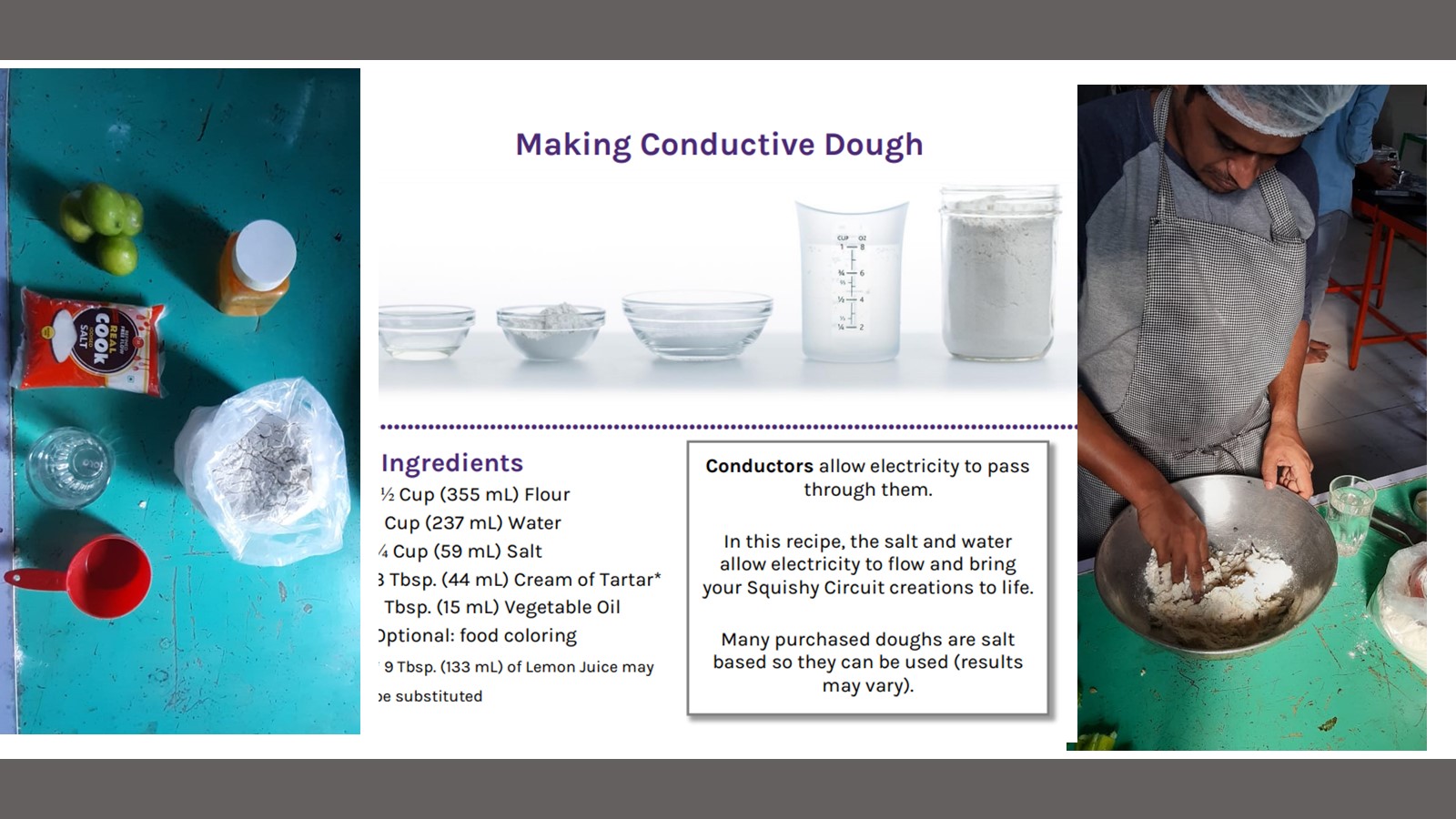
We have the clay. But as per the recipe, we need to do the cooking operation. And we failed to make
it smooth. It was smooth but not so smooth that the extruder could print. The cooking of dough is an
uncontrollable task.
We checked the conductivity of the clay. We created a simple circuit by hand and lightened the
Led by attaching a power supply. It was working means the recipe was ok.
I have measured the resistance of the circuit shown in the figure.
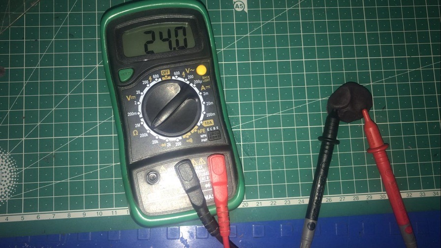
To make a clay printable, it should be smooth and give consistency during printing.
Extruder Design
In this machine, the critical task is to design the extruder for clay printing.
Then I searched the online resources for the extruder design. I come to the youtube video of
Constantijn Crijnen. He has given excellent insights of the clay and extruder.
He has designed a printer that can print 3d objects with clay.
He has given one extruder design on the Thingiverse extruder model. I have studied it and decided to make it with 3d printing. Extruder designed by the Constantijn Crijnen is using 60 ml syringe. We want to design a 2.5 axis, an extruder that can move x and y direction, and rotation about the z-axis means we want to create 2d circuits. 60ml syringe is too big for our printer. But to check the possibility of printing our clay, we have printed the parts designed and uploaded on Thingiverse extruder model. by Constantijn Crijnen.
After printing the parts, we assembled the extruder with stepper motor Nema 17 with 3kgm torque and
tried to extrude conductive clay. But the clay was very viscous due to which extreme load acted on
the motor and its mises steps.
As per the dimensions of our machine to accommodate the assembly of a 60ml syringe, it is too heavy. Then I decided to redesign the extruder for the 20ml syringe. I want to make it very simple and easy to assemble.
I have taken the reference of Constantijn Crijnen Thingiverse extruder design to design the extruder for clay circuit printing.
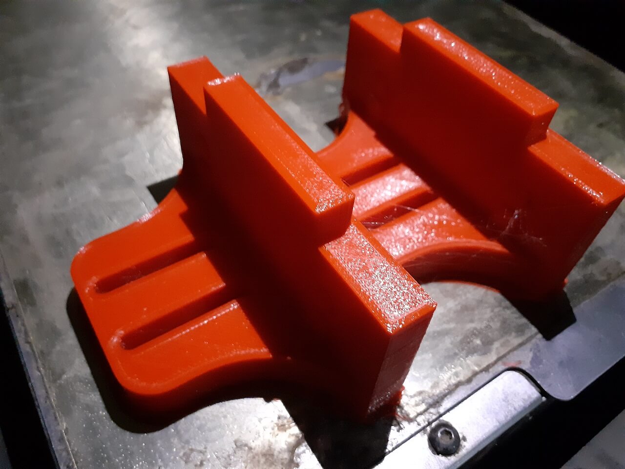
Then I made the extruder design using a 6mm acrylic sheet. Acrylic sheet is brittle in nature; it can handle compressive stress.
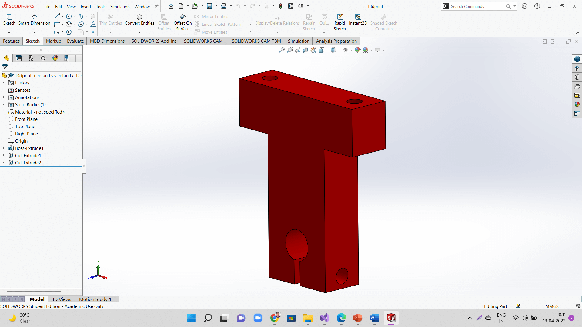
Solid Modelling
I have designed the extruder in Solidworks software. I have designed the extruder for the 20ml syringe.
I have considered the stroke length of the syringe, the coupler required to connect the lead screw to the plunger of the syringes, and other fitting required. The total length of the extruder was 210mm. The housing of the extruder was designed using a 6mm acrylic sheet. The following video shows the exploded view of the extruder design.
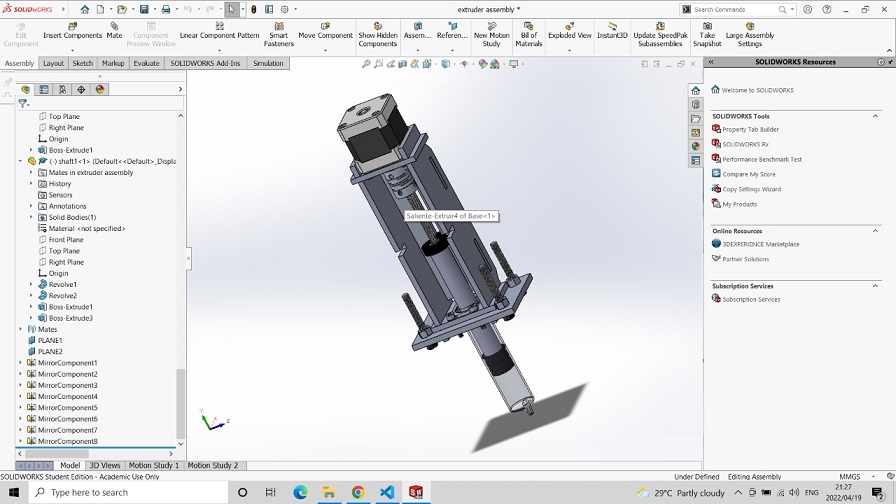
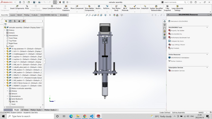
The following video shows the exploded view of the extruder design.
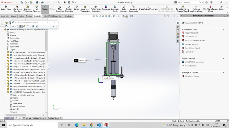
I have simulated the model according to the lead screw I have chosen and assigned the screw mate in the mechanical mate feature of assembly.
Distance per revolution of the screw thread (lead) is measured and assigned value 1mm/rev.
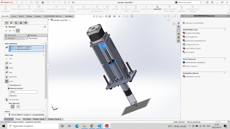
The whole process of the extrusion mechanism is simulated using Solidworks motion analysis is as shown below:
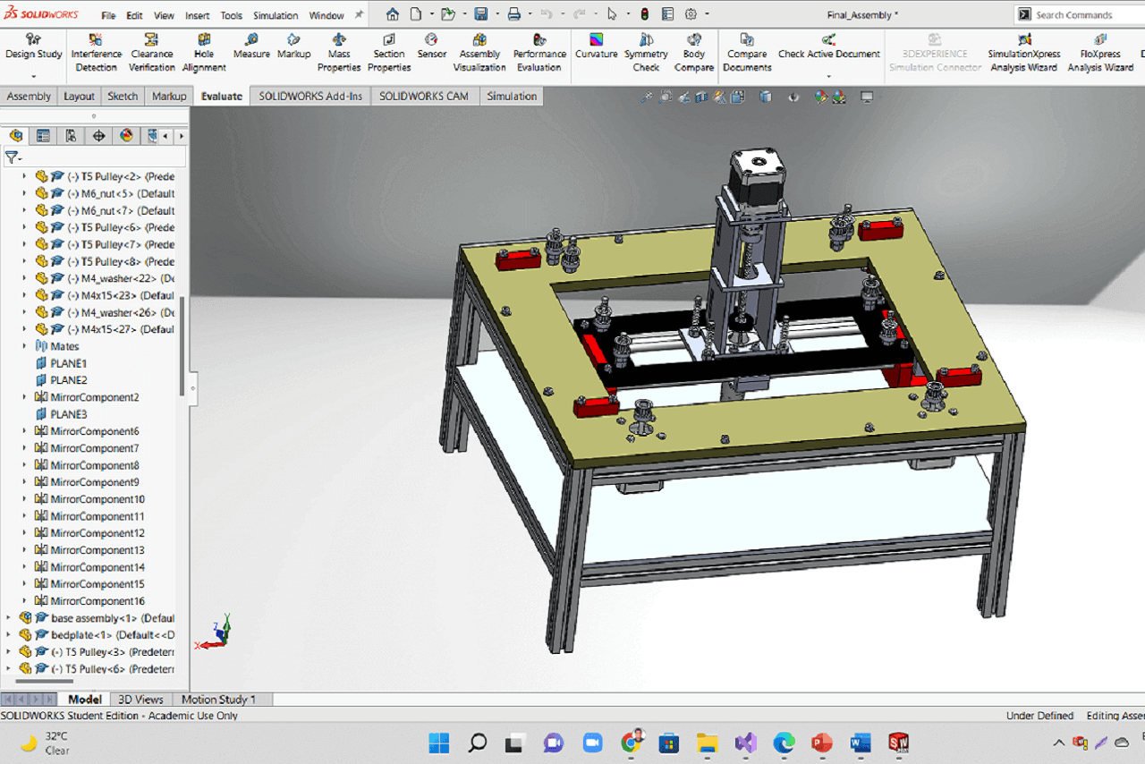
Then Kishore sir has made complete assembly of our clay printer.
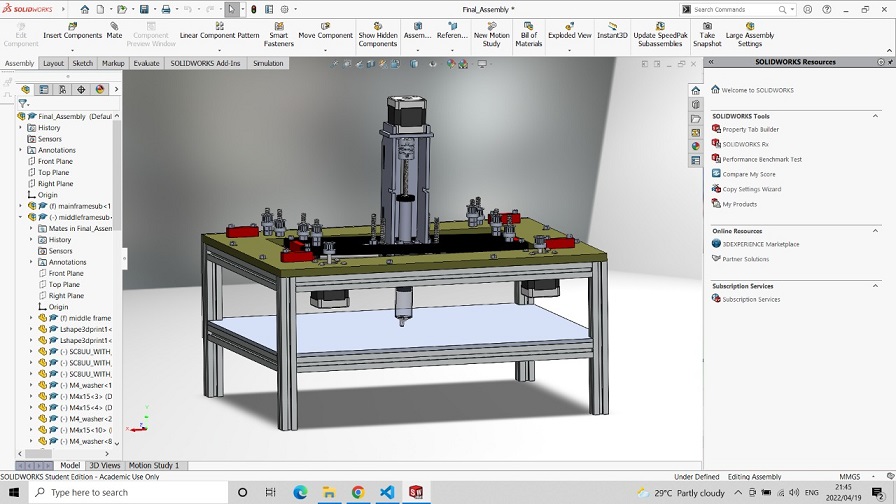
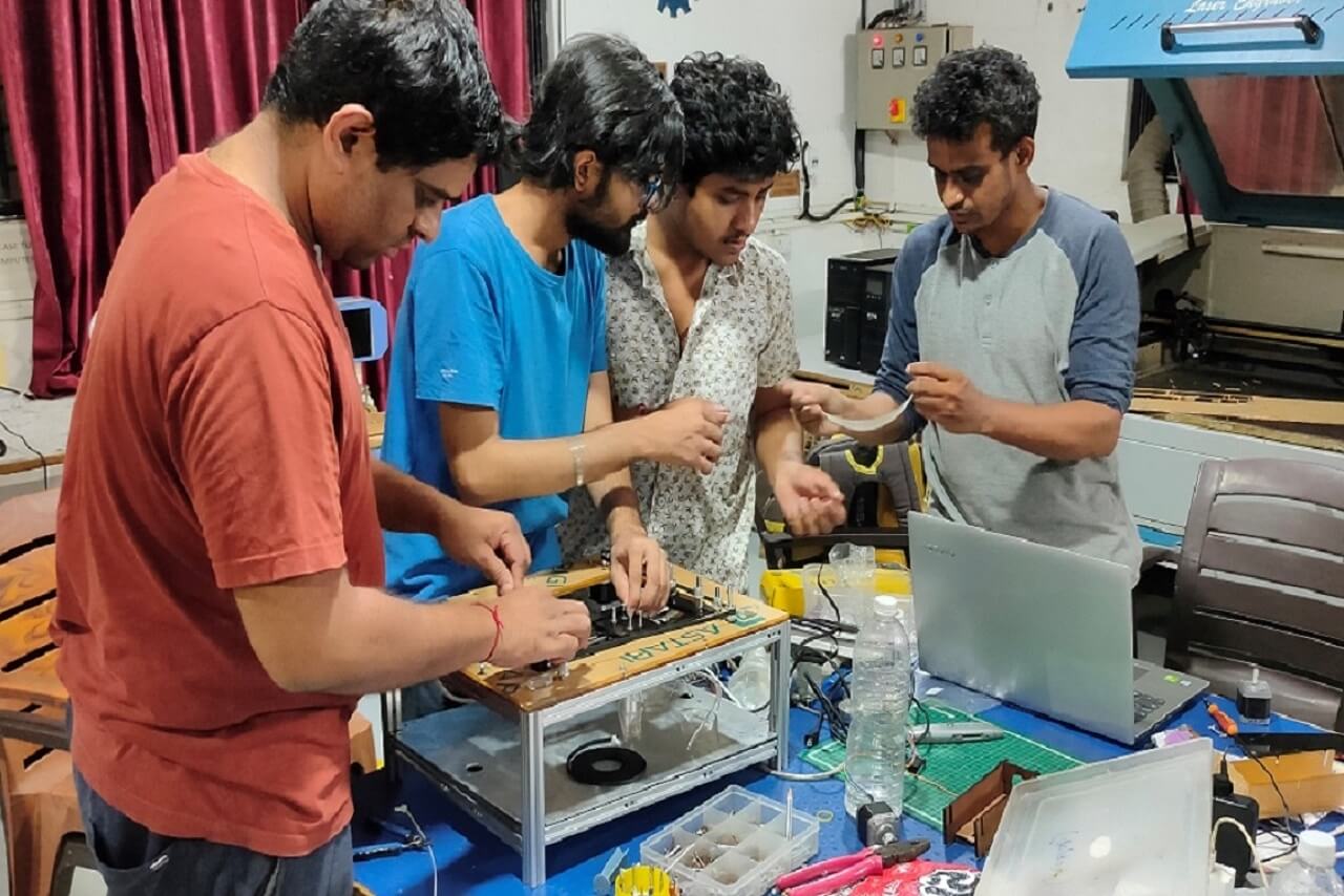
After designing the extruder assembly, all the necessary cutting parts were cut using a laser machine and assembled on the machine body.
Extruder Assembly
After cutting parts on the Laser cutting machine, assemble them on the main body of the machine. The following video shows the procedure of change of clay and assembly of the extruder for printing.
Extrusion multiplier:
For our printer, we will use merlin firmware specially designed for 3d printing with 3-axis movement of the extruder. And extrude used in the 3D printing is just different from the extruder for the clay printing. To print the clay using Merling firmware, we must change the Marlin firmware and the G code set.
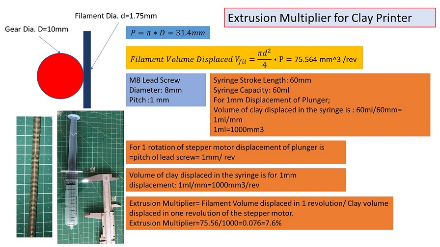
Extrusion speed in FFF 3D printing and Clay printing should be different. So by referring to this video, I have calculated multiplying factor for the initial layer flow. It was 7.6%. In Cura software, I have changed the setting of initial flow from 100% to 7.6%.
Cura Software Setting
One of our team was working on the slicer to generate .ocde. We have decided to work on the Ultimaker Cura for the gcode to give some advanced settings to create a toolpath effectively.
Ultimaker Cura generates printer-specific g-code by slicing the user's model file into layers. Once completed, the g-code can be submitted to the printer for physical object fabrication. The open source program can work with files in the most common 3D formats, including STL, OBJ, X3D, and 3MF, and picture file formats, including BMP, GIF, JPG, and PNG, and is compatible with most desktop 3D printers. Ref. Wikipedia Cura official Website to download the model.
Following steps were followed to setup our clay printer and geretare the .gcode in Cura.
.JPG)
.JPG)
.JPG)
.JPG)
.JPG)
.JPG)
I have made some initial settings for printing the three led circuits drawn in Solidworks and imported them through the .stl file into the Cura.
.JPG)
.JPG)
.JPG)
.JPG)
Extrusion speed in FFF 3D printing and Clay printing should be different. So by referring to this video, I have calculated multiplying factor for the initial layer flow. It was 7.6%. In Cura software, I have changed the setting of initial flow from 100% to 7.6%. In our case, we want to print small circuits without any support, brim, or raft. So I have disabled them.
.JPG)
.JPG)
Pronterface is a graphical user interface for the printer's host software. It's part of a Printrun
software suite that includes several G-code utility programs. Pronterface is the software that
allows you to control your 3D printer. This approach is based on the assumption that you already
have all of the necessary software installed. Please see our tutorial on installing the essential
software if you don't already have it.
Begin using a USB cord to connect your 3D printer to your computer. Connect the 3D printer to
the power source and plug it into a power socket. Next, open Pronterface by going to the directory
where Pronterface was installed (i.e. C: Pronterface) and double-clicking on the Pronterface.exe
icon. Select the com port your 3D printer is connected to once Pronterface loads, and then set the
baud rate to 250000. Then press the connect button. In Pronterface's right column, you'll see a
message stating that the printer has been successfully connected.
To use the pronterface, connect the shield to the PC, then start the pronterface on the computer. The
com ports and baud rate are set in the upper left corner. The shield will provide you information
about itself and say it is connected when you touch the 'Connect' button. Click the X, Y, and Z-axis
controls to engage the motors and confirm that the hardware and software are in sync. As shown in
the video below, we can now determine and configure the machine's direction (+X, -X, +Y, and -Y)
through trial and error.
Ref. 1. Pronterface Official Website 2. Revolutioni3
tutorial
.JPG)
Final Clay Circuit Printing
After creating the code, we initially tried to draw a hexagon by attaching the pen to the extruder. Initially, it took some different layers, and then it started drawing. Trial video shows below:
Then I have tried to print the logo of Fab lab, but it was failed shown below:
After a lot of trial and error, we succeed in printing the circuit using clay shown below:
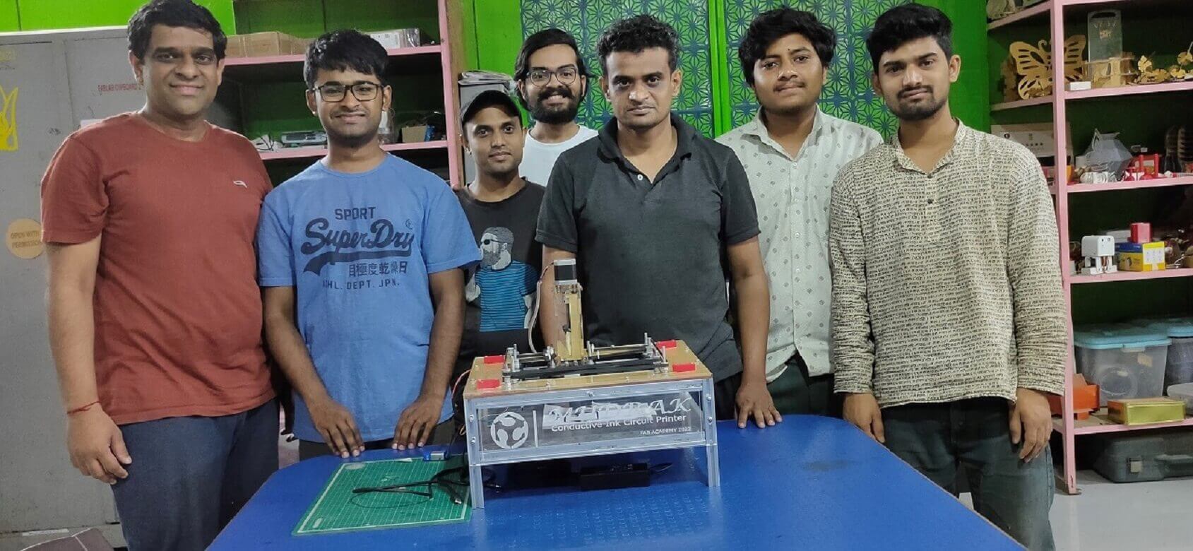
Finally, we completed the circuit using conductive clay by attaching 3leds and a 9V power supply.
We decided to Name "Mudrak," the Hindi word for "Printer," in the name-keeping ceremony.Ha Ha...
I want to thank the Instructors, All my teammates for their immense efforts; we could finish the printer. Thank you.
My Major Contributions in the Make a Machine
Finalization of mechanism for the actuation:
After PROF. Neil's lecture has gone through different mechanisms like Gantry type; lead screw
operated X-Y-Z motion, Delta type, and core X-Y. We have finalized the core X-Y mechanism for our
machine.
3D modeling of mainframe and some of its components
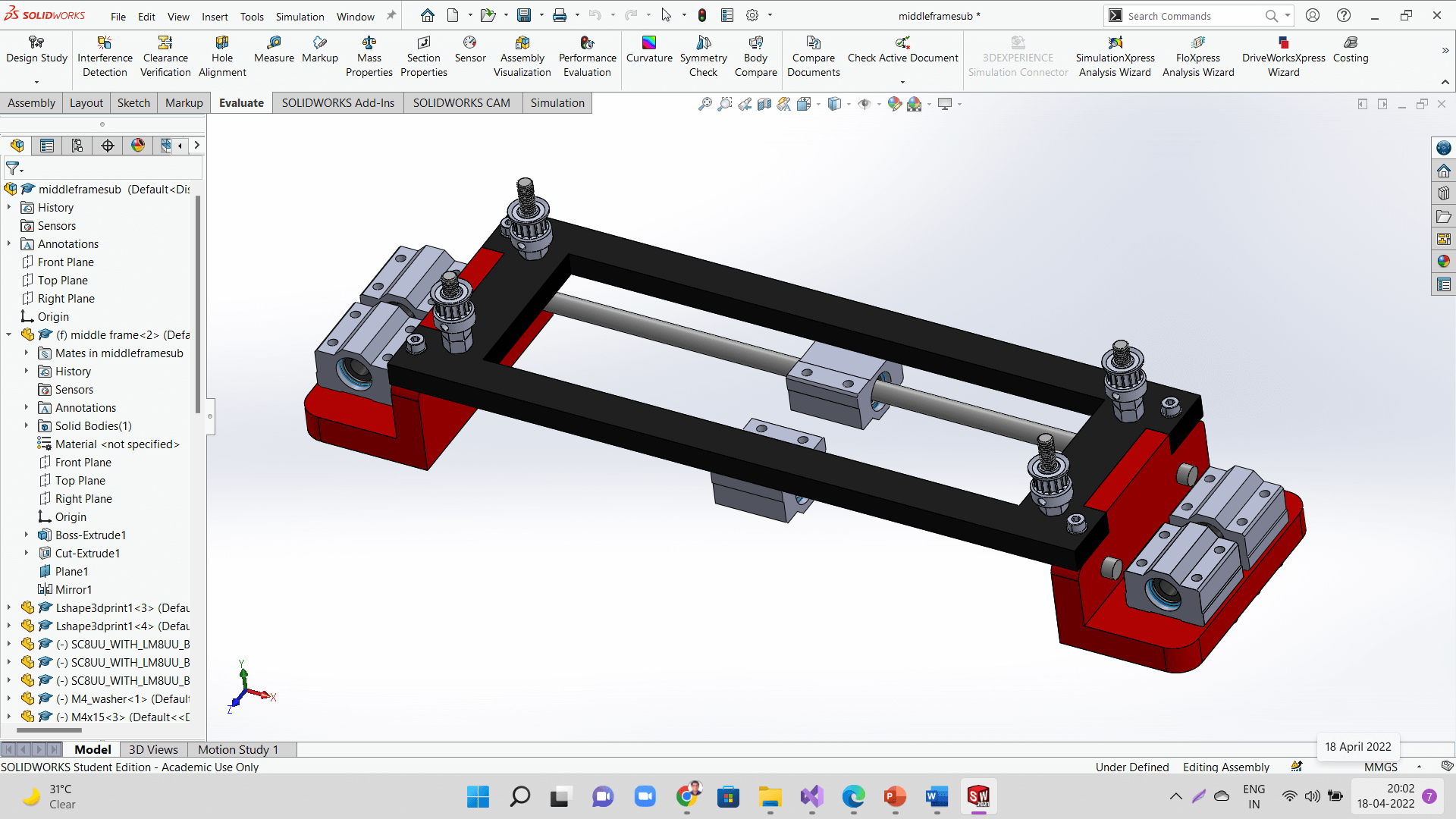
I have contributed to the design of the mainframe, bearing supports, and a subframe for the
extruder, which cut the subframe using a laser cutting machine.
I have also contributed to troubleshooting the core x-y mechanism due to the single bearing on each
side.
I have designed the bearing supports and 3d Print them.
CoreXY: Kinematics for Personal Fabrication from Ilan Moyer on Vimeo.
Design and development of extruder for clay and ink printing
We also develop the conductive ink using charcoal, paint, salt, adhesive, and water. We have used this video to prepare the conductive ink.
I have used this video for making conductive ink.
Develop the conductive ink and clay
Inkmaking from Kishore Gaikwad on Vimeo.
Configuration of the printer with Cura and generate the tool path for different circuit designs
Mechanical Design
I have participated in the assembly of the frame and the mechanical design of the printer.
Machine Design:
I have also contributed to the machine design, like changes in the Marlin firmware code, bed size, pitch, and speed of extruder motor in the firmware Arduino code.
Future Scope
As we know, the cross-section area increases resistance decreases. So I will try to increase the width of the circuit layer to transfer more current and make more interactive circuits with motors, buzzers, etc.