Embedded Programming
Individual Assignment:
Read the data sheet for your microcontroller.
Use your programmer to program your board to do something.
Extra credit: try other programming languages and development environments
Group Assignment:
Compare the performance and development workflows for other architectures.
This week's assignment was fascinating, and I enjoyed it while doing the task. I would like to thanks
Dr. Neil Sir, MY instructor Suhas Sir, Kishor Sir, and my batchmates for giving insights about
Embedded programming.
After Electronics Production and Electronics design week, I understand some electronics components
basics. This week's assignments helped me learn about Datasheet, different architecture, memory
types, boards, and Programming of Embedded Systems.
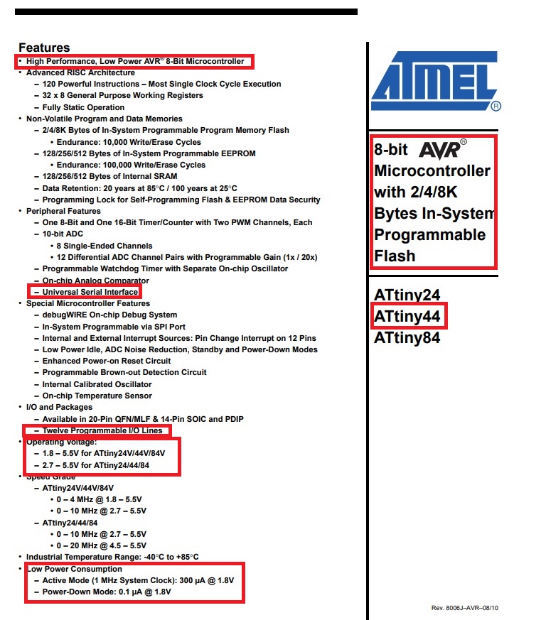
Datasheet Attiny 44
A datasheet, also known as a spec sheet, is a document that specifies the performance and other
attributes of a product, machine, component, material, subsystem, or software in precise detail for
a buyer to understand the product and a technical expert to understand the component's role in the
overall system.Ref: Wikipedia
Then I have searched online about the Datasheet of ATtiny 44. I found the Datasheet on
following Website
While selecting the microprocessor, we need to see about Power requirement, no. of Input-output
pins, no. of bits, Pinout, Cache, In-system Programmer EEROM etc.
The pinout is the assignment of the functions of the pins in various connectors, or in radio-electronic components such as microcircuits, transistors, relays, according to their reference numbering.
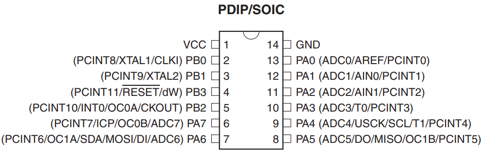
Pin Functions
VCC Supply voltage.
GNDGround.
Port B (PB3:PB0)
Port B is a 4-bit bi-directional I/O port with internal pull-up resistors (selected for each bit).
The
Port B output buffers have symmetrical drive characteristics with both high sink and source
capability except PB3 which has the RESET capability. To use pin PB3 as an I/O pin, instead of
RESET pin, program (‘0’) RSTDISBL fuse. As inputs, Port B pins that are externally pulled low
will source current if the pull-up resistors are activated. The Port B pins are tri-stated when a
reset condition becomes active, even if the clock is not running.
RESET
Reset input. A low level on this pin for longer than the minimum pulse length will generate a
reset, even if the clock is not running and provided the reset pin has not been disabled. Shorter
pulses are not guaranteed to generate a reset.
The reset pin can also be used as a (weak) I/O pin.
Port A (PA7:PA0)
Port A is a 8-bit bi-directional I/O port with internal pull-up resistors (selected for each bit).
The
Port A output buffers have symmetrical drive characteristics with both high sink and source
capability. As inputs, Port A pins that are externally pulled low will source current if the pull-up
resistors are activated. The Port A pins are tri-stated when a reset condition becomes active,
even if the clock is not running. Port A has alternate functions as analog inputs for the ADC,
analog comparator, timer/counter.
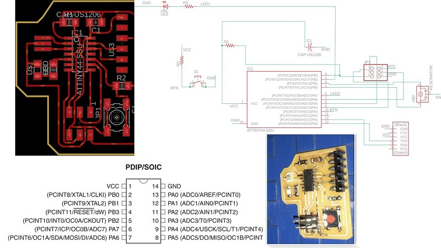
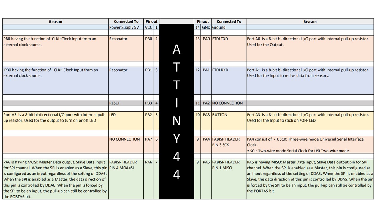
Hello Board PCB connections
In the Hello board, we have used ATtiny 44 microcontroller. To program the PCB, I need to understand
Datasheet, pinout, supply voltage, etc.
I started reading its Datasheet, basic understanding features, and pinout for its programming.
After reading the Datasheet, I tried to correlate PCB design USB tiny ISP design with Datasheet.
Then I realized why we had connected PB2 to LED, PB1, and PB3 to the resonator, Pins for the
Programming header, and pins for the output Pins.
Programming
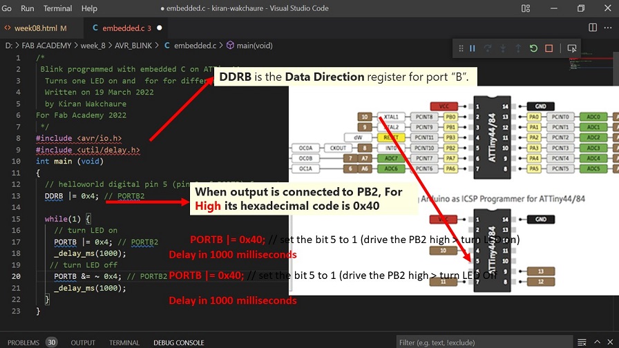
Embedded C is the most widely used programming language in the software industry for creating electronic devices. I have used VScode to write the program to blink the LED of my Hello World board.
/*
Blink programmed with embedded C on ATTiny44
Turns one LED on and for for different interval of time.
Written on 19 March 2022
by Kiran Wakchaure
For Fab Academy 2022
*/
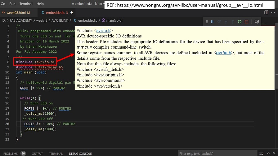
#include
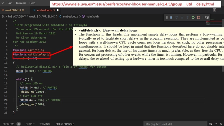
#include
int main (void)
{
// helloworld digital pin 5 (pin 2 of PORTB) for output
DDRB |= 0x4; // PORTB2
while(1) {
// turn LED on
PORTB |= 0x4; // PORTB2
_delay_ms(1000);
// turn LED off
PORTB &= ~ 0x4; // PORTB2
_delay_ms(1000);
}
}
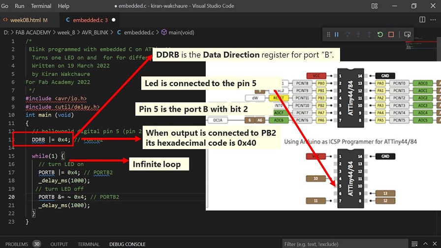
For my PCB, I have connected the LED to Pin no. 5 of ATTinny 44. To give the output to pin 5, we need to store the data with hex code for a particular register. Pin 5 is the Port B, Bit 2 (PB2). When PB2 is high, it switches on the LED. To give the unique address to each port, we need to use binary or Hexadecimal code.
I have used AVR due to run the program on my PCB.I have followed detailed procedure to install GNU AVR toolchain on Windows 10 using Link was already done during Electronics production week to check FABISP.
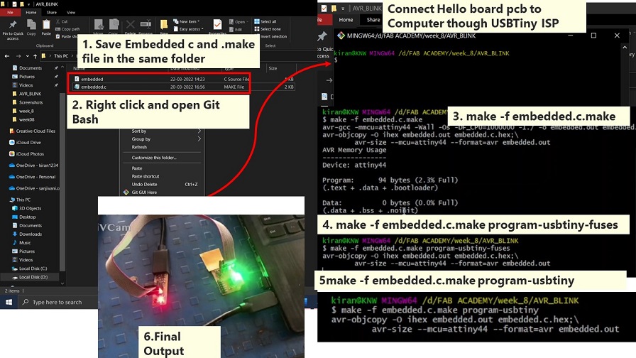
Code used to run the program on Hello board is shown here.
make -f embedded.c.make

                    make -f embedded.c.make program-usbtiny-fuses

                    make -f embedded.c.make program-usbtiny
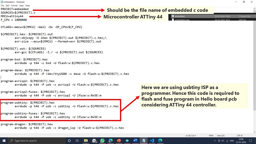
Make File
Make is a build automation tool for software development that creates executable programs and libraries from source code by reading Makefiles, which define how to derive the target program. Make is still widely used, notably in Unix and Unix-like operating systems, despite the availability of integrated development environments and language-specific compiler capabilities. Make may handle any project where specific files must be updated automatically if others change and produce programs.
Detailed Procedure to run Program using AVR GNU
Hello Board Programming with Binary code
Hello Board Programming with Hex code
Group Assignment:
You can find a detailed Group assignment here.
Compare the performance and development workflows for other architectures.
| Comparison of Microcontroller Architectures | ||||
|---|---|---|---|---|
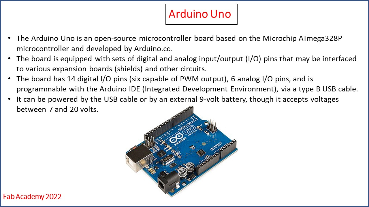
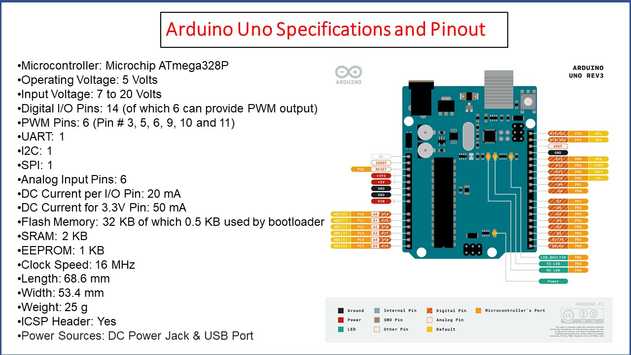
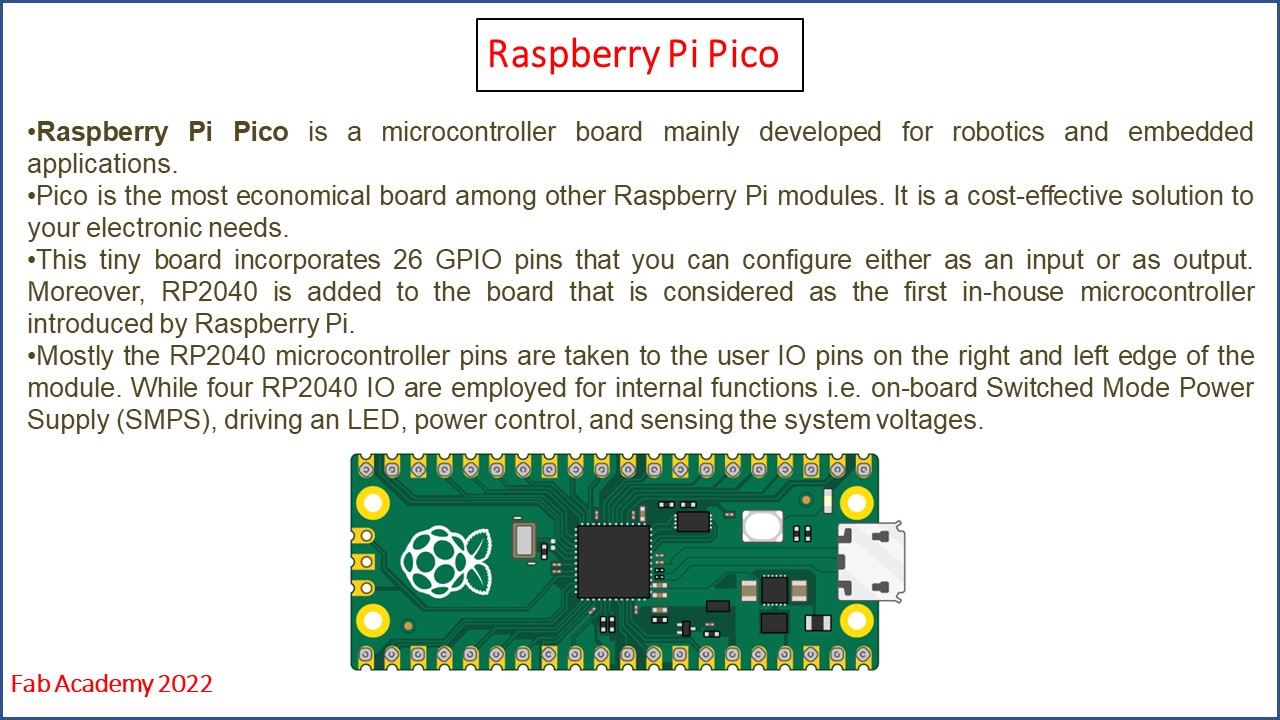
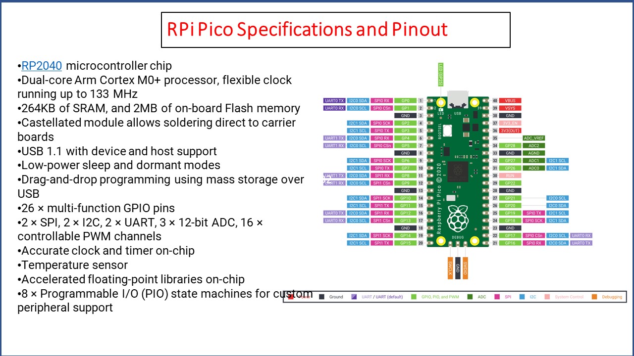
| Sr No. | Parameters | Arduino Uno | ESP 32 | Raspberry Pi Pico |
| 1 | Operating Voltage | 5V | 3.3V | 16mA |
| 2 | DC current on I/O pins | 40mA | 40mA | 3.3V |
| 3 | Digital I/O pins | 14 | 39 | 26 |
| 4 | Flash Memory | 32KB | 4MB | 2Mbyte(Q-SPI Flash) |
| 5 | Frequency | 16MHz | 40MHz | 48MHz/133MHz |
| 6 | Wi-Fi | - | 802.11b/g/n | - |
| 7 | Bluetooth | - | V4.2 | - |
| 8 | Microcontroller | ATmega328p | Xtensa LX6 | RP2040 |
| 9 | Architecture | Harvard | Harvard | Harvard |
Arduino board Programming with Arduino IDE
Raspberry Pi Pico Programming with Thonny
ESP 32 Board Programming with Thonny
Downloads
Program files
LED Blink -Embedded C Make File.
LED Blink Arduino Binary code .
LED Blink on Raspberry Pi Pico Board .
Basics of Embedded Systems
Initially, I started understanding basic electronics programming requirements like Architecture, memory, Pinouts, etc.
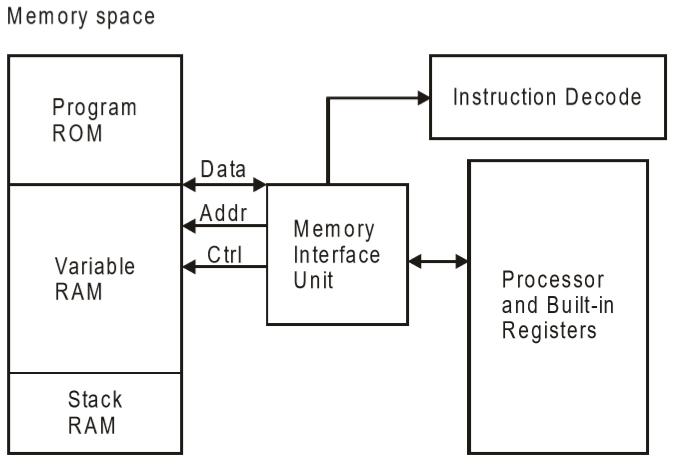
The architecture of the Embedded System includes sensors, Analog to Digital Converter, Memory, Processor, Digital to Analog Converter, Actuators, etc.
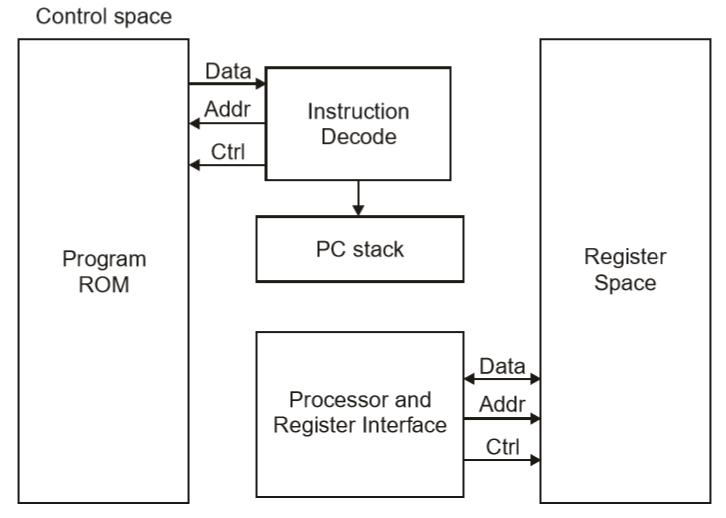
Embedded systems consist of two types of architectures: Havard architecture and Von Neumann
architecture.
In Harvard architecture, data and code are stored in distinct memory blocks. And in Von Neumann's
architecture, data and code are stored in the same memory block.
The Harvard design provides distinct storage and signal buses for instructions and data. The data
storage is totally contained within the CPU, and there is no access to the instruction storage as
data in this design. Using internal data buses, computers have distinct memory locations for program
instructions and data, enabling simultaneous access.
There is no requirement to have the two memories share attributes in Harvard architecture.
John von Neumann, a computer scientist, was the first to propose the Von Neumann architecture. In
this design, both instruction and data are carried on a single data route or bus. As a result, the
CPU can only carry out one activity at a time. It either reads or writes data or retrieves an
instruction from memory. As a result, an instruction fetch and a data operation cannot occur on the
same bus.
The Von-Neumann architecture supports simple hardware. It makes it possible to employ a single,
sequential memory. We use a fast but tiny quantity of memory (cache) local to the processor since
today's processing speeds considerably outperform memory access times.
CISC and RISC
CISC is a Complex Instruction Set Computer. It is a computer that can address a large number of
instructions.
RISC is a Reduced Instruction Set Computer. It is a computer that can address a fewer
instructions with simple construction.
| CISC AND RISK | ||
|---|---|---|
| CISC | RISC | |
| Larger set of instructions. Easy to program | Smaller set of Instructions. Difficult to program. | |
| Simpler design of compiler, considering larger set of instructions. | Complex design of compiler. | |
| Many addressing modes causing complex instruction formats. | Few addressing modes, fix instruction format. | |
| Instruction length is variable. | Instruction length varies. | |
| Higher clock cycles per second. | Low clock cycle per second. | |
| Emphasis is on hardware. | Emphasis is on software. | |
| Control unit implements large instruction set using micro-program unit. | Each instruction is to be executed by hardware. | |
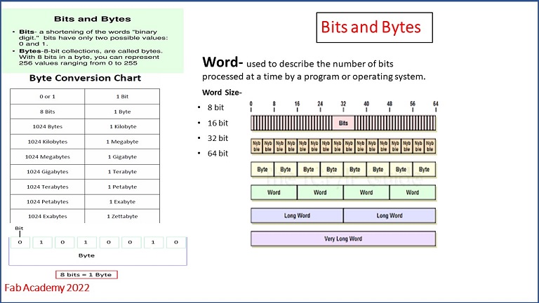
Bits and Bytes
Memory
Memory is a data storage technology that can store or save data, temporarily or permanently. The data stored are in a binary form such as 0 and 1, allowing the user to save and retrieve the information anytime they require it.
Microprocessor and Microcontroller
| Microprocessor and Microcontroller | ||
|---|---|---|
| Microprocessor | Microcontroller | |
| Microprocessors are multitasking in nature. Can perform multiple tasks at a time. For example, on computer we can play music while writing text in text editor. | Single task oriented. For example, a washing machine is designed for washing clothes only. | |
| RAM, ROM, I/O Ports, and Timers can be added externally and can vary in numbers. | RAM, ROM, I/O Ports, and Timers cannot be added externally. These components are to be embedded together on a chip and are fixed in numbers. | |
| Designers can decide the number of memory or I/O ports needed. | Fixed number for memory or I/O makes a microcontroller ideal for a limited but specific task. | |
| External support of external memory and I/O ports makes a microprocessor-based system heavier and costlier. | Microcontrollers are lightweight and cheaper than a microprocessor. | |
| External devices require more space and their power consumption is higher. | A microcontroller-based system consumes less power and takes less space. | |
| Selective laser melting (SLM) or direct metal laser sintering (DMLS) | Soft and hard metals | |