Computer-controlled machining
• Group assignment:
Complete your lab’s safety training
Test runout, alignment, speeds, feeds, and toolpaths for your machine
Document your work to the group work page and reflect on your individual page what you learned
• Individual assignment:
• Make (design+mill+assemble) something big
Group
Assignment can be found here.
Group assignment is about the lab safety training and learning about various process parameters of Shopbot machine to machine the parts. Shopbot is a huge machine; a small mistake may lead to severe health issues. So We used Hearing protection and eye protection glasses while using the machine. My Instruction Mrs. Apeksha Kulkarni working as an Assistant professor at COEP, has given instructions on safety measures. Then, she has given training in working the machine, using fixtures to clamp the plywood on the bed, mounting the tool in the collet, and tool path generation using partworks software.
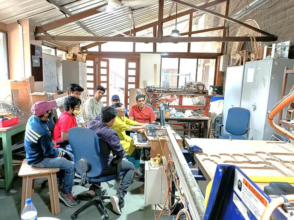
We learned how to do clamping for the plywood stock on the bed of the Shopbot.
We learned about safety precautions and used safety equipment during machining the job.
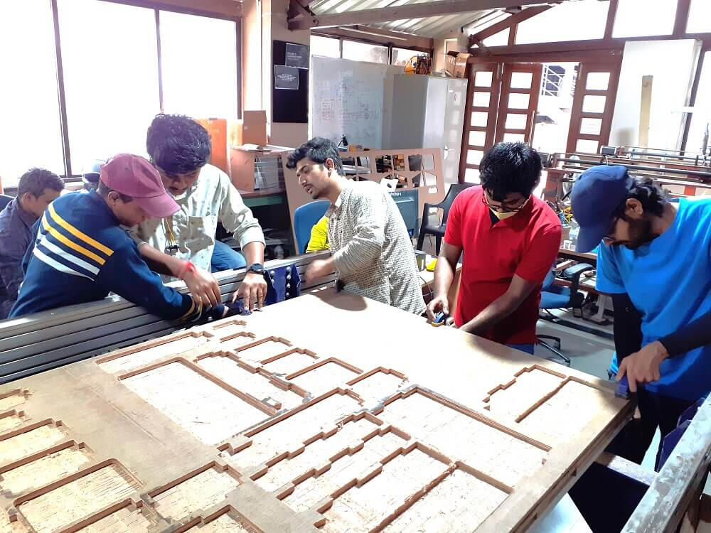
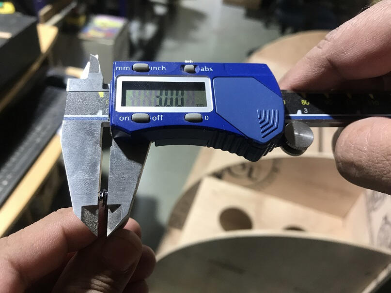
After learning the basics of fixturing and tooling for press-fit joints, it was important for us to learn the settings for speed, feed, material, and toolpaths generation during test runouts on the machine in order to get a good understanding of how parts are cut.
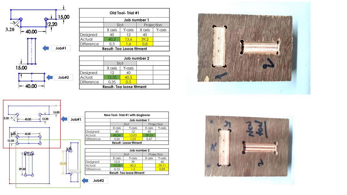
Then, using Solidworks, we created T-shaped slots and projections aligned with the machine's X
and Y axes. The dimensions we used in the design for cutting slots and projection were as
follows. On the other hand, the tasks would not fit as well as in press-fit joints. For features
oriented along the machine's Y-axis, there was a gap of 1 mm to 1.6 mm between the intended and
actual dimensions. The gap between design and actual dimensions was 0.3 to 0.8 mm along the
X-axis.
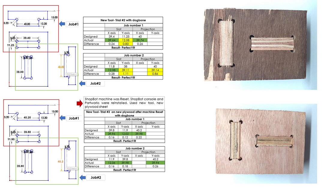
We next replaced tools, using a new carbide tool, and ran a few more trials. To avoid fillet
radius at the sharp corners, we used a dog bone at the corners this time. The designed and
actual dimensions are listed below. However, we still saw significant disparities in size along
the Y axis in this trial. We couldn't figure out why the mismatch between the designed and
actual dimensions occurred just on the Y axis. We could draw the only conclusion that the
machine's Y-axis motor had a 1-1.6 mm inaccuracy. In this study as well, the result was loose
fittings.
As a result, we decided to make these changes to the planned dimensions solely to compensate for the Y-axis mistake. As a result, the intended dimensions to accomplish the requisite dimensions are as follows. The fitment was flawless this time, and both tasks were a press-fit. As a result, to produce satisfactory press-fit joints even with a Y-axis inaccuracy, we decided to make the following alterations to the intended dimensions. It's also challenging to make these design adjustments in every slot and projection. Using this strategy, designing would be complex. To avoid the design mentioned above, we chose to reset the machine, uninstall and reinstall ShopBot console software, reset the USB port used for communication, and replace the plywood sheet. The dimensions of the jobs as designed versus actual are listed here. We didn't make any changes to the design this time, and there were no mistakes in the dimensions along either axis.
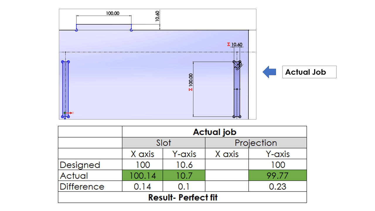
Then, we employed the following design dimensions in our individual assignment jobs and received the following outcomes with good press-fit joints. We didn't have to adjust to our original dimensions, and it was really simple.
In this assignment, we learned about safety measures using a large CNC machine. Also learned about fixturing, tool path generation, selection of optimum parameters for the cutting, and hand-on exposure of machining.
Introduction
Computer-aided manufacturing/Machining (CAM) uses software to control machine tools and related ones in manufacturing workpieces. CAM may also refer to using a computer to assist in all operations of a manufacturing plant, including planning, management, transportation, and storage. Its primary purpose is to create a faster production process and components and to tool with more precise dimensions and material consistency, which in some cases, uses only the required amount of raw material (thus minimizing waste) while simultaneously reducing energy consumption.
Some dedicated Cam softwares available are Mastercam, Gibbscam, FeatureCAM, etc. All the Cad
modeling software companies integrated cam features like Autodesk Fusion, Inventor, Solidworks
Cam, Siemens Unigraphics, PTC Creo, etc.
• Individual assignment:
This week's assignment is to create something big that will involve design machining and Assembly
of its components with press-fit only (without using glue and nails.)
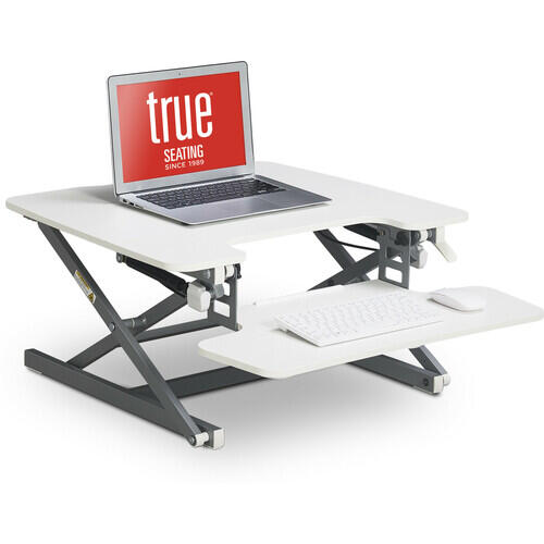
The present assignment is to develop the sit-stand workstation to reduce the sitting time and
ease of working for a long time.
In some professions like (IT industries), people need to sit for a long time. Sitting for a long
time is very harmful to health. Sitting for more than eight hours can lead to postural problems
like disc damage, strained neck, and swayed back in the long run.
So I have decided to develop the sit-stand workstation to reduce human fatigue.
Changing sitting to standing and walking around will improve blood circulation and muscle
exercise. This will also increase concentration during working and ultimately increase
productivity.
Working continuously in standing and sitting positions for more than 1 hour is not suitable for
health. who work at a desk spend a lot of time sitting and sit-stand workstations have been
highlighted as a viable technique for reducing sitting time.
References
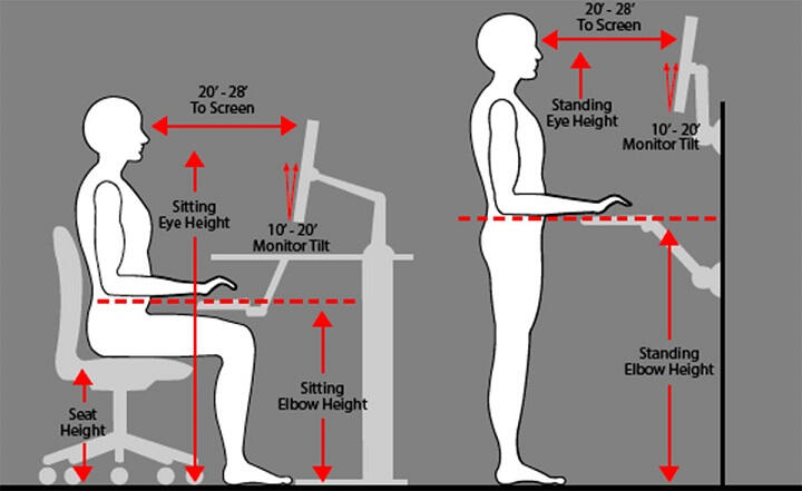
Proper Workspace
ergonomics
Research Paper
sitting to standing workstations
Some Available Designs
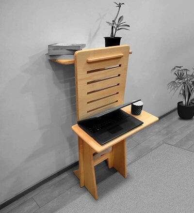

Initial Design
I have chosen the second model for this week's assignment on Computer-aided manufacturing.
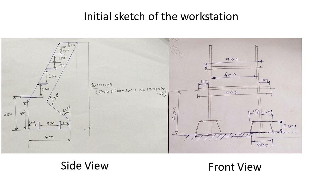
The initial design was made by considering ergonomics for sitting and standing positions in the workspace. .
I have decided to make it adjustable and suitable for all age groups. And should be easy to handle.
Initially, I have drawn a rough sketch of my design to get an idea of it.
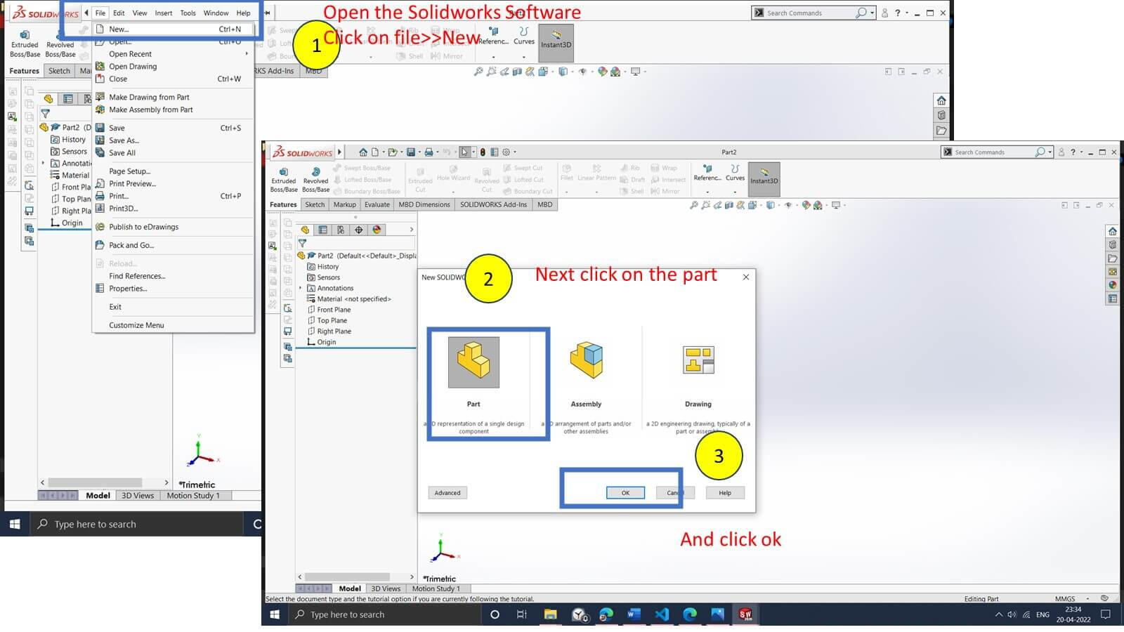
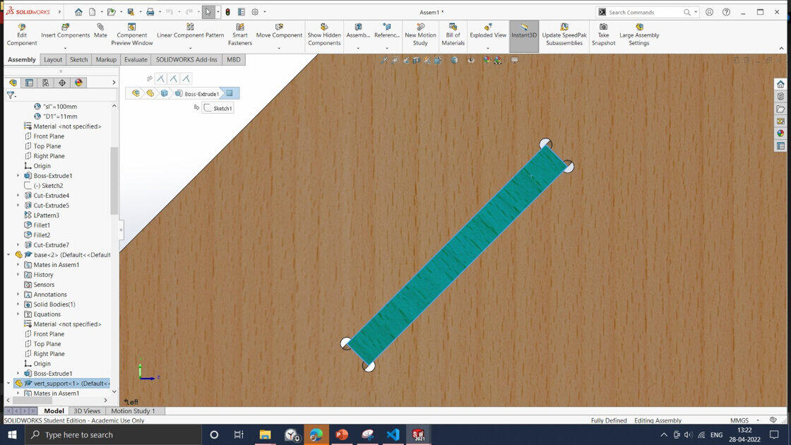
Part Modelling
For the part modeling, I have used Solidworks software. For the part modeling, I have used parametric modeling. Here we are using plywood to make a workbench table with 11 mm thickness. But someone who wants to use the same for the 10 mm thick parametric modeling will be helpful to them in building the table.
All the parts of the assembly and its dimensions are shown below.
.jpg)
.jpg)
.jpg)
.jpg)
.jpg)
.jpg)
.jpg)
.jpg)
.jpg)
.jpg)
.jpg)
All the part files are exported as .dxf files for the toolpath generation.
Final Design
Dogbone Filets.
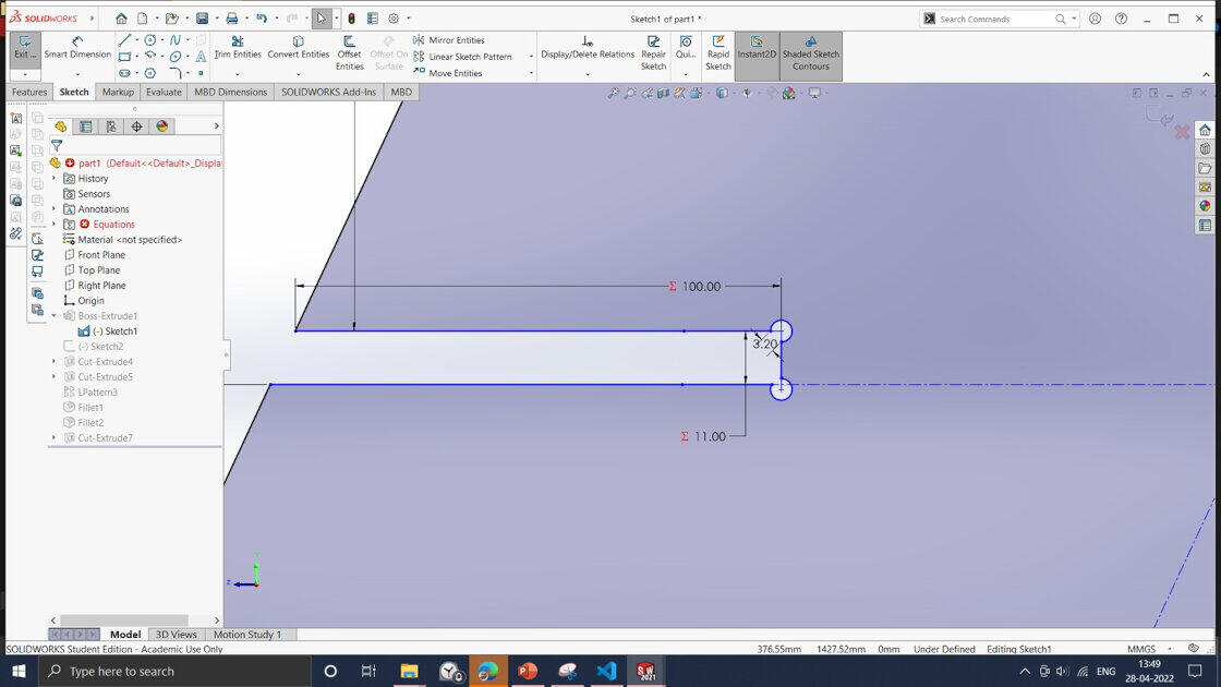
While using milling operation, tools radius is assigned to the inner pocket edges of the machining part. The inner radius creates a problem for the mating of the parts. For the press-fitting, it's desired to add dog bone shape fillet to inner corners to accommodate the sharp projection of other parts. I am using Solidworks software for designing. To get a press-fit Assembly, I need to add a dog bone shape in the design process. Solidworks doesn't have any feature like Dogbone fillet. So I have made all the fillets manually in the Solidworks software.
In this case, I am using a 3mm diameter endmill flat tool. So I have created a dogbone fillet entry path of 3.2mm wide. So that tool can quickly move inside the fillets and remove the critical path. If the entry path size is less than 3mm, the dogbone shape will not be created because programming software automatically considers tool diameter and omit that part from the machining.
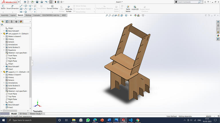
Following Assembly shows press-fitting of mating components of the table using Dogbone shape fillets..
Manufacturing
Tool-Path Generation
Machining
A ShopBot is a all-in-one tool for accurately cutting, carving, drilling, and machining a wide range of materials. With a ShopBot, you design your components on your computer using the supplied software, and then the computer, directs the cutter to accurately cut your parts.
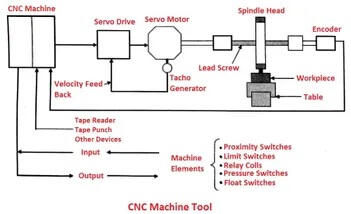
:>Fast, closed-loop Vexta alphaStep motors fitted with low-backlash, tapered-hob gear heads on
all three axes (two on the X axis) -- alphaStep system monitors motor shaft positions to
maintain synchronicity between signal and motion.
:>Tough precision linear bearings on the moving gantry and hardened steel rails for the x-axis.
:>Reliable rack-and-pinion power transmission on each axis.
:>Impressive cutting speeds of up to 600 inches per minute (depending on cutting bit and
material) and rapid transit speeds of 1,800 inches per minute.
:>Step resolution of .0004”.
:>Positional accuracy of +/- .002”.
:>Sealed Industrial UL Certified Control Box.
:>Emergency Stop disconnect switch in the Control Box with integrated and cabled remote
Emergency Stop Buttons.
:>Z-zero Touch-Off Plate and XY Proximity Switches.
:>ShopBot Control System software to run your CNC.
:>Dust Skirt ready to connect to your dust collector.
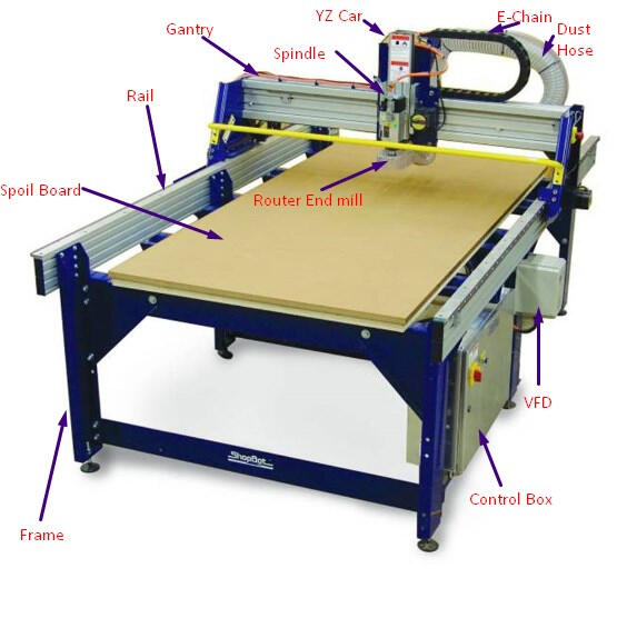
More detailed specifications of the shopbot machine shown below.

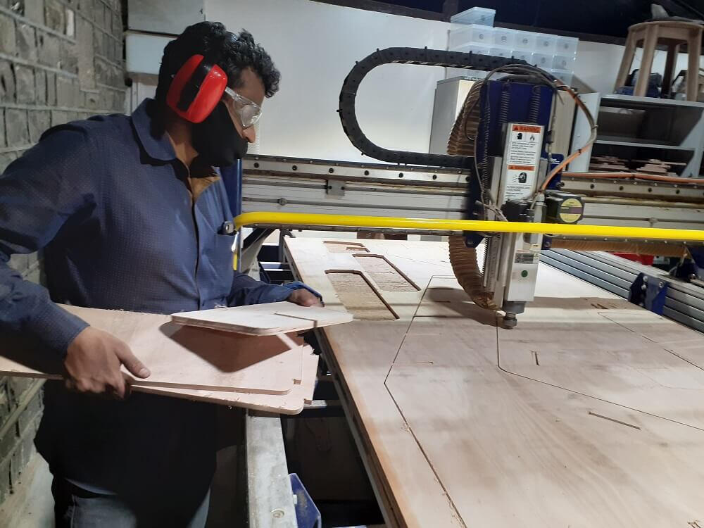
Precautions during Machining
All the machining should be done under the trained lab supervisor's observation.
- Always wear safety glasses with side shields and hearing protection while using the
Shopbot machine.
- While the ShopBot and router are running, keep your eyes, hands, hair, and clothing away
from them.
- Always use your senses: see, hear, and smell.
Toolpath Generation using partworks software
PartWorks is Shopbot's proprietary software tool to generate the toolpath for the cutting operation. The figure shows GUI of PartWorks software.
.jpg)
I have converted Solidworks .sldprt 3d files into the .dxf file and imported them into the PartWorks software.
.jpg)
.jpg)
Then I have selected all the machining parameters in the software like tool diameter, depth of cut, no. of cutting passes, spindle speed, feed rate, plunge rate machine vector inside out, etc.
.jpg)
.jpg)
For the proper utilization of 8x4 plywood sheet, I and my teammate Mr. Kishore sir, has combined both the .dxf file and nested them properly.
.jpg)
Toolpaths can be viewed in 2D and 3D, as shown below. This toolpath will also assist us in visualizing areas on our stock where we can hammer nails to improve its hold. Then I generated the gcode with file extension .sbp for the shopbot machine.
.jpg)
I have rigidly clamped plywood on the bed of the machine. I have then fixed the end mill flat tool with a 3mm diameter in the collet of the spindle.
.jpg)
I switched the machine and checked emergency switches, made them open, and clicked on the reset shown below.
.jpg)
Then I have open the output port open for the moving x-y-z axis.
.jpg)
It shows the current position of the tool. By the manual jogging operation, I set zero position at the leftmost corner of the sheet. And by switching on the spindle, slowly allow the moving tool in a downward direction to set z zero for the tool.
.jpg)
I loaded gcode .sbp file in the shopbot console.
.jpg)
I have switched on the dust collector. And then, I started the machining operation on the shopbot machine.
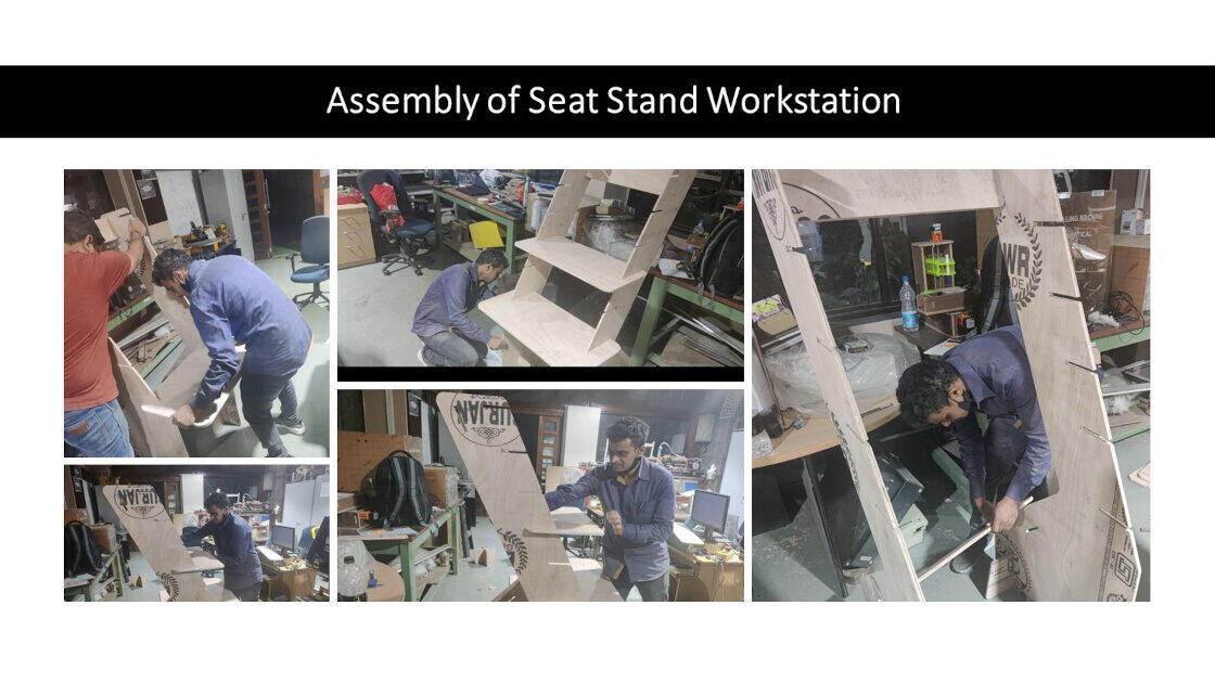
Assembling
After machining all the parts, I assembled them and set up my Set-Stand workstation. And I could assemble it without using nails or glue.
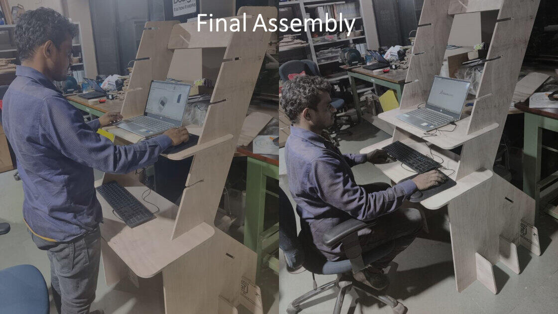
Final Trial
At last, I have taken a trial to see if I can work on the workbench in seating and standing positions. I feel very proud of using the setup I have designed, machined, and assembled.
Learning Outcomes
I learned how to construct toolpaths for routers using Partworks software.
I learned the fundamentals of computer-controlled machining (large-format machining),
tooling and fixturing, and various routing materials, their properties, and uses, among other
things. –
I became familiar with the ShopBot interface.
I figured out how to alter the router's end mill.
I learned the necessity of following safety procedures, receiving proper training, and
remaining vigilant while the router is turned on.
Downloads
parts .dxf files can be download from here.