3D Scanning and Printing
Group Assignment
You can find a detailed Group assignment here.
Test the design rules for your 3D printer(s)
Individual Assignment
1: Design and 3D print an object that could not be made subtractively
2: 3D scan an object (and optionally print it)
About Additive manufacturing
Test the design rules for your 3D printer(s)
Introduction
Manufacturing Processes creates or produces items using machinery, labor, machinery, tools, and chemical or biological processing or formulation. Manufacturing engineering, often known as the manufacturing process, refers to converting raw material into a finished product.
There are three basic manufacturing processes to develop the products: additive, subtractive, and forming.
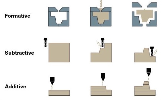
Subtractive manufacturing refers to a variety of controlled machining and material removal methods that begin with solid blocks, bars, or rods of plastic, metal, or other materials formed by removing material by cutting, boring, drilling, and grinding. These procedures can be done manually or, more typically, with the use of computer numerical control (CNC).
| Subtractive Manufacturing Processes | ||
|---|---|---|
| PROCESS | MATERIALS | |
| CNC machining (turning, drilling, boring, milling, reaming) | Hard thermoplastics, thermoset plastics, soft metals, hard metals (industrial machines) | |
| Electrical discharge machining (EDM) | Hard metals | |
| Laser cutting | Thermoplastics, wood, acrylic, fabrics, metals (industrial machines) | |
| Water jet cutting | Plastics, hard and soft metals, stone, glass, composites | |
Metal forming is a wide range of manufacturing processes in which metal is deformed into a required shape by applying suitable stresses. To make the metal plastically deformed, forces must be used greater than the metals' yield strength. The magnitude of the compression, stretching or bending in the material is directly proportional to the force applied. Some of the commonly used forming processes in the manufacturing industry are: Casting, Moulding, Forging, Rolling, Extrusion, Thread rolling, Rotary swaging, Explosive forming.
Additive Manufacturing also referred as 3D printing using Slicer tool 3D model is converted in to the number of layers as a toolpath and dedicated device called as 3D printer creates the actual model layer by layer.
| Additive Manufacturing Processes | ||
|---|---|---|
| PROCESS | MATERIALS | |
| Stereolithography (SLA) | Varieties of resin (thermoset plastics), high-strength, rigid, flexible, elastic, heat-resistant, castable (wax-like) | |
| Selective laser sintering (SLS) | Engineering thermoplastics, such as nylon | |
| Fused deposition modeling (FDM) | Standard thermoplastics, such as ABS, PLA, and their various blends | |
| Material jetting | Varieties of resin (thermosetting plastics) | |
| Binder jetting | Gypsum (full color), metals | |
| Selective laser melting (SLM) or direct metal laser sintering (DMLS) | Soft and hard metals | |
3D Printer
A 3D printer is a material design printer that uses an additive manufacturing technique to create 3D models and products of devices and components.
FDM
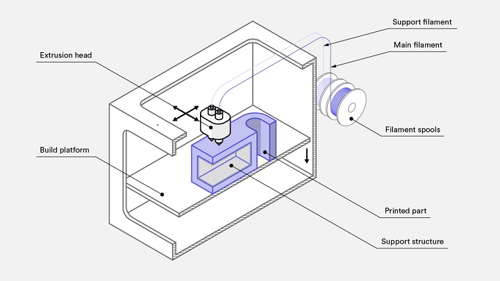
Fused deposition modeling (FDM), commonly known as fused filament fabrication (FFF), is an additive manufacturing technique that belongs to the material extrusion category. A product is constructed in FDM by layer, selectively depositing melted material along a predefined direction. The materials are thermoplastic polymers that come in the form of filaments. The most used 3D printing technology is FDM. It has the world's most extensive installed base of 3D printers and is frequently the first 3D printing technology that consumers come across.
Procedure of Additive manufacturing processes
Working of FDM Printer
The wide range of materials available for use in FDM, which includes commodity thermoplastics (such as PLA and ABS ), engineering materials (such as PA, TPU, and PETG ), and high-performance thermoplastics (such as PEEK and PEI ), is one of its primary strengths.
Commonly used materials in the FDM 3D Printing
- PLA: Polylactic acid (PLA) is a vegetable-based plastic polymer frequently made using maize
starch as a primary raw material. It is biodegradable since it is a thermoplastic polymer
created from essential renewable resources. PLA is the most widely used material for 3d
PRINTING. PLA filament deforms or melts when exposed to high temperatures, making it
unsuitable for heat-resistant components.PLA is an elementary material to print with. PLA
has a low print temperature compared to other filaments, and it will generally flow out of
your 3D printer's nozzle without clogging. PLA is inexpensive, perhaps the most major
advantage of printing with it. PLA is a low to medium strength filament due to its limited
heat and chemical resistance. It also tends to break when hit.
- ABS: ABS (acrylonitrile butadiene styrene) is an opaque thermoplastic widely used in home
and consumer goods. Following PLA, it is one of the most used filament kinds. ABS is also
suitable for injection molding and machining, in addition to 3D printing. ABS is a robust,
resilient, and long-lasting Material. It has high heat and impact resistance. Before
breaking, it undergoes some deformation, making it ideal for products used frequently in
daily life. Toxic fumes are generated during the printing of ABS, making dealing with the
material difficult. Either a filtering system or a separate, appropriately aired area is
required to print. ABS is a medium to a high-strength filament that will bend rather than
break and is more resistant to impact, heat, and chemicals than PLA.
- PETG: Thermoplastic polyethylene terephthalate glycol (PETG) has material
qualities that make it viable for practical items. PETG may be
found in a variety of products like water bottles and food containers. PETG is considered as
a food-safe material. It may be used to produce cooking accessories, camping utensils,
containers, and other items that come into touch with food. PETG, like ABS, is UV light
sensitive hence it's best suited for indoor applications. PETG becomes highly brittle and
weak when exposed to UV radiation, leaving any objects unusable.
PETG is also a filament with a medium to high tensile strength. It's similar to ABS in
appearance, but it's stronger, mainly when weights are applied in the same direction as the
layer lines.
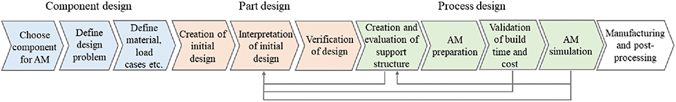
Process of Design for Additive Manufacturing
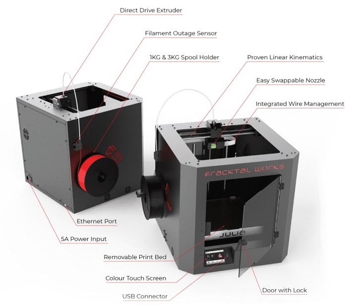
Our 3D Printer
In our lab, we have Fractal works make Julia Advance desktop 3D printer. Schematic of 3D printer shown below;
Machine Specifications
- Machine Size: 435 mm x 445 mm x 385 mm
- Build Volume: 200 mm x 200 mm x 200 mm
- Print Technology: FFF
- Filament Diameter: 1.75 mm
- Nozzle Diameter: 0.4 mm
- Nozzle Temperatures: Upto 280 °C
- Build Plate: Temperature Upto 150 °C
- Feeder Type: Direct Drive
- Calibration: Active Automatic Leveling & Calibration
- Build Speed: Upto 40 mm³/s
- Build Plate: PEI Flexbuild Surface For all other materials Nylon Surface For Nylon,
Nylon CF
- Operating Temperature: 15°C to 35°C Recommended
- Compatible Materials: ABS, PLA, Tough PLA, PLA+, PETg, PVA, PVA+, BVOH,Polycarbonate,
Nylon 12*, Carbon Fiber Nylon*, Carbon Fiber PLA
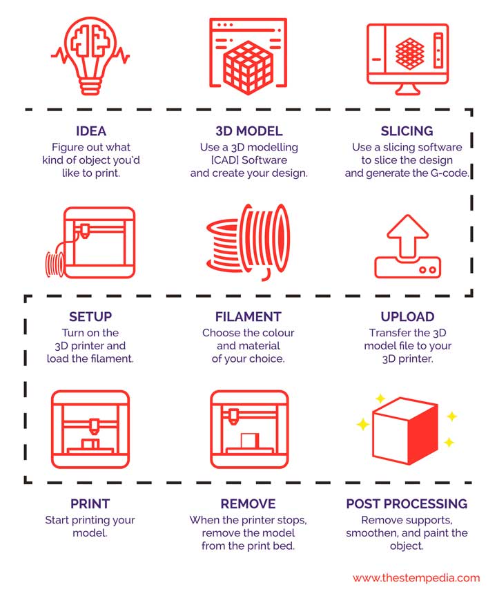
Steps involved in the 3D printing
- Step 1 :Design the required model in solid modelling software by
considering design rules for 3D printer (Design for Additive Manufacturing) and convert it
into .slt or .obj file formats
- Step 2 :Generate the tool path using any slicing software like Cura/ Prusa
slicer/ Simplify3D by assigning layer height, printing speed, bed temperature, nozzle
temperature, bed adhesion type Skirt/ Raft, Support etc.
- Step 3 :Start the 3D printer and load the filament
- Step 4 :Clean the bed and make sure there no any foreign particles on the
bed which impacts printing operation.
- Step 5 :Do the bed leveling of the printer to ensure proper adhesion of
first layer.
- Step 6 :Heat the print bed and the nozzle as per the material required
during the printing.
- Step 7 :Clean the nozzle and ensure uniform extrusion.
- Step 8 :Start the Print and make sure first layer is uniform. It it is not
proper adjust the bed using bed leveling screws.
- Step 9 :Do not touch the Nozzle and the print bed during the printing
operation.
- Step 10 :After printing operation use spatula to remove the part from the
bed.
- Step 11 :Remove the support material carefully without damaging main part.
Group Assignment
You can find a detailed Group assignment here.
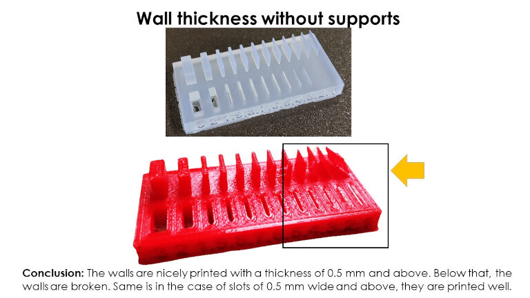
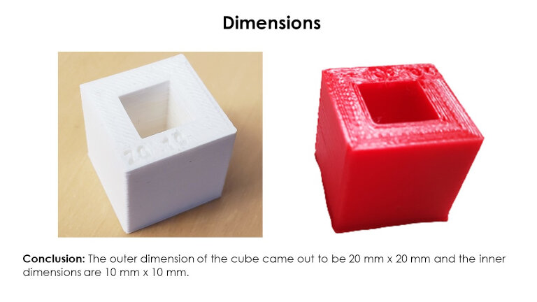
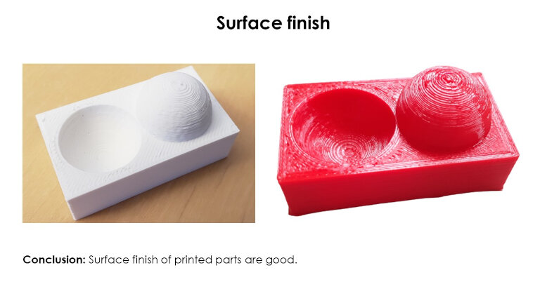
Test the design rules for your 3D printer(s)
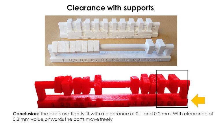
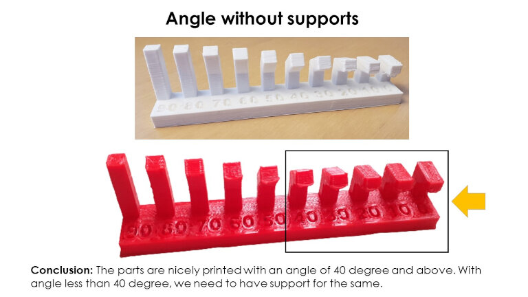
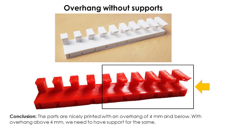
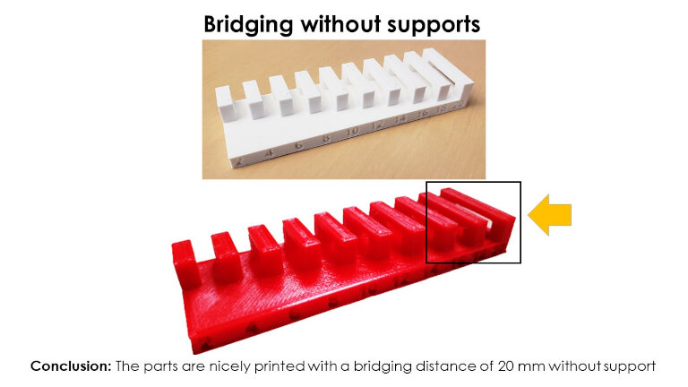
This week's group assignment is about the set design rules for our 3D Printer. Fab Academy has given standard 3D parts to test the accuracy, precision, and capability of our 3d Printer. We have downloaded the parts and printed them with our 3D Printer.
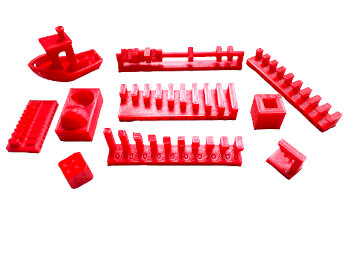
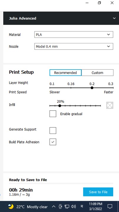
All the parts are printed with the PLA material with following Parameter settings;
Design Rules for our 3D printer.
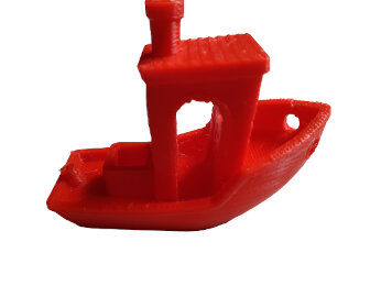
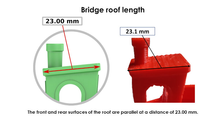
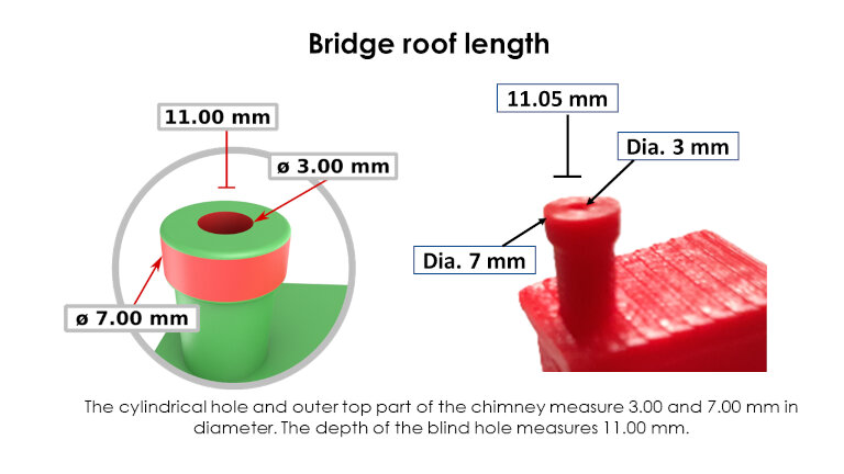
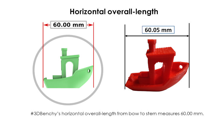
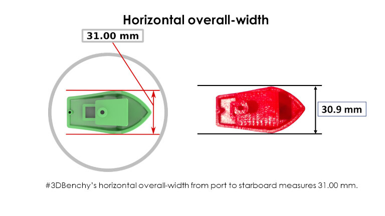
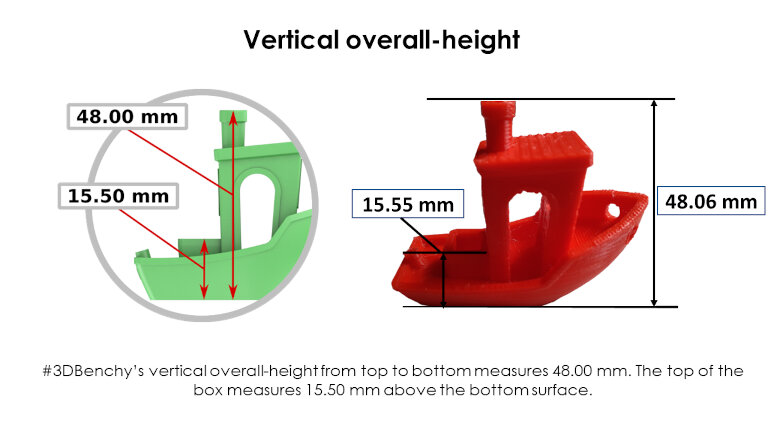
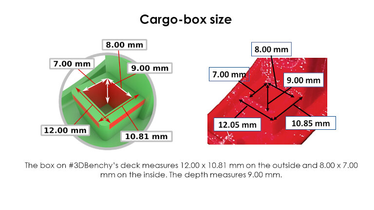
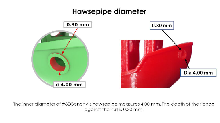
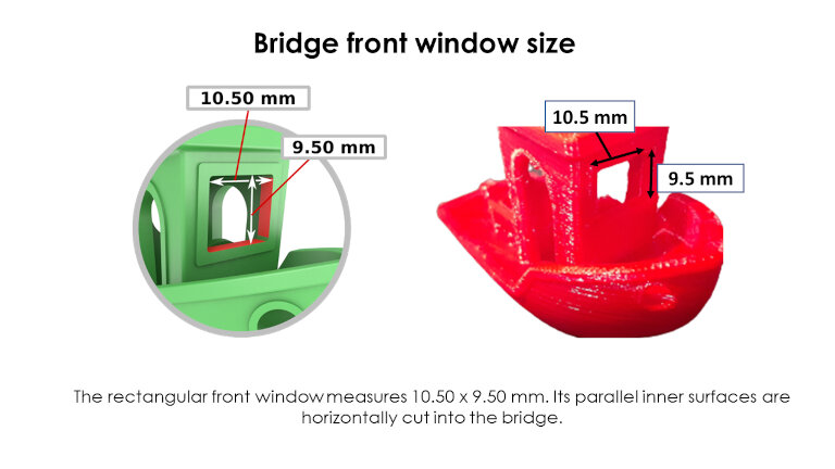
We have also used Benchy Torture test to study the Accuracy and capability of our 3d Printer.
#3DBenchy is a 3D model specifically designed for testing and benchmarking 3D printers. #3DBenchy is designed to offer an extensive array of challenging geometrical features for 3D printers and touch on different issues related to additive manufacturing.
Ref:#3D Benchy Website https://www.3dbenchy.com/ Part is downloaded from https://www.thingiverse.com/thing:763622
Individual Assignment
1: Design and 3D print an object that could not be made subtractively
Part 1: Compliant Mechanism
I was fascinated by the compliant mechanism. So I have decided to design a compliant mechanism as an individual assignment of the week. Then I referred to the Compliant Mechanisms Research Group (CMR) of Brigham Young University of United States. I have finalized a small plier for the assignment by understanding basic concepts.
A compliant mechanism is a flexible mechanism that achieves force and motion transmission through elastic body deformation. It gains some or all of its motion from the relative flexibility of its members rather than from rigid-body joints alone. These are monolithic (single-piece) jointless structures. Compliant mechanisms examples are backpack latches and paper clips.
Ref: https://www.compliantmechanisms.byu.edu/about-compliant-mechanisms
I have decided to print compliant mechanisms using 3d printing. I have created the compliant mechanism plier by searching several compliant mechanisms on the internet.
I have downloaded an image of the compliant mechanism and imported it into Solidworks software. And tracing the image manually, I have sketched the plier. Then, I have extruded a sketch for 5mm.
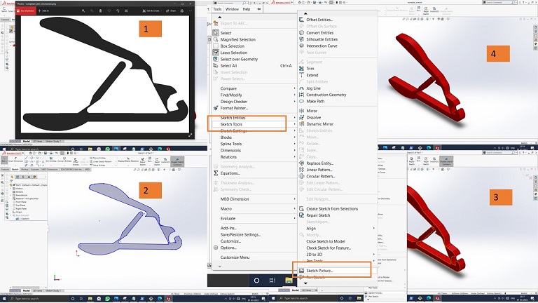
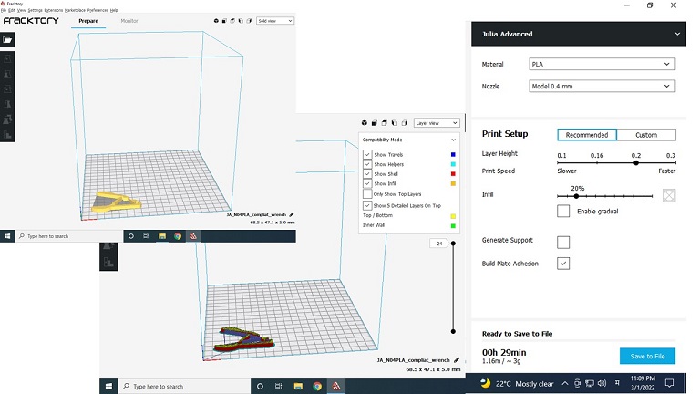
Then the model is converted into the .stl format. And imported in Fraktory Slicer tool to generate the tool path. Parameters set during toolpath shown below,
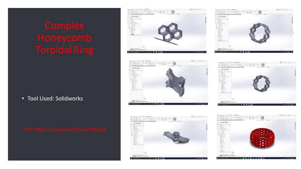
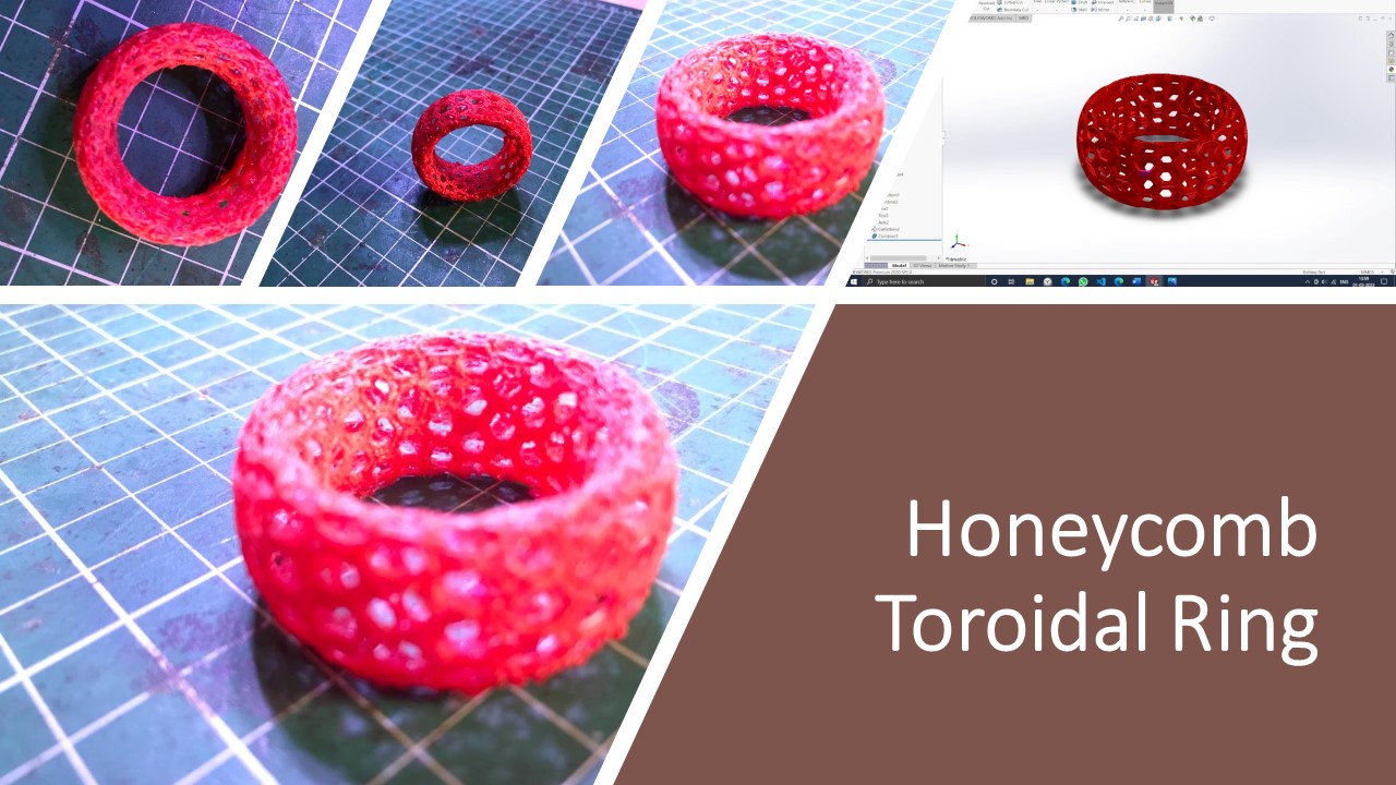
Part 2: Complex Honeycomb Toroidal Ring
The individual Assignment task was to design and 3D print an object that could not be made with a subtractive manufacturing process. I search a lot of resources on the internet. I tried to design regenerative design using Fusion 360 but failed. Then I have decided to move with Solidworks and create a complex Honeycomb toroidal ring that is highly impossible to manufacture with a subtractive manufacturing process.
The process of drawing part is as shown below. I have used youtube tutorial of Toroidal Ring using Solidworks. YouTube tutorial of Toroidal Ring using Solidworks.
Following video shows the different commands used during 3D modelling.
For 3D printing, parameters used are 0.2 mm layer height and 60mm /min printing speed 60mm/min without any support with PLA material.The final 3D printed part is shown below.
2: 3D scan an object (and optionally print it)
3D Scanning is to turn a real-world object like an action figure, a room, an entire building, or anything else that can be scanned into a virtual model of that object in 3D form. 3D Scanning is done with a 3D scanner to take a video or set of pictures of the object and convert into 3D form and can be saved in the .obj and .sl format. A camera with an infrared sensor can be used to make 3D scans. They can measure the depth of field with this camera.
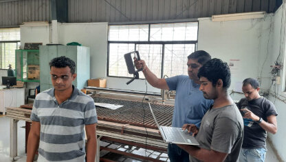
We have the 'Sense 3D Scanner' of 3D Systems, Inc., which is one of the easiest to use and handy scanners in our lab. You point the scanner at the object to scan and start moving the thing or move the camera such that you cover almost all sides of the object.

Specification of Scanner
- Scan Volume: 0.2m x 0.2m 0.2m (min) (Lower the better) 2m x 2m x 2m (max) (Higher the
better)r
- Depth Resolution at 0.5m: 1mm
- Spatial X/Y resolution at 0.5m: 0.9mm
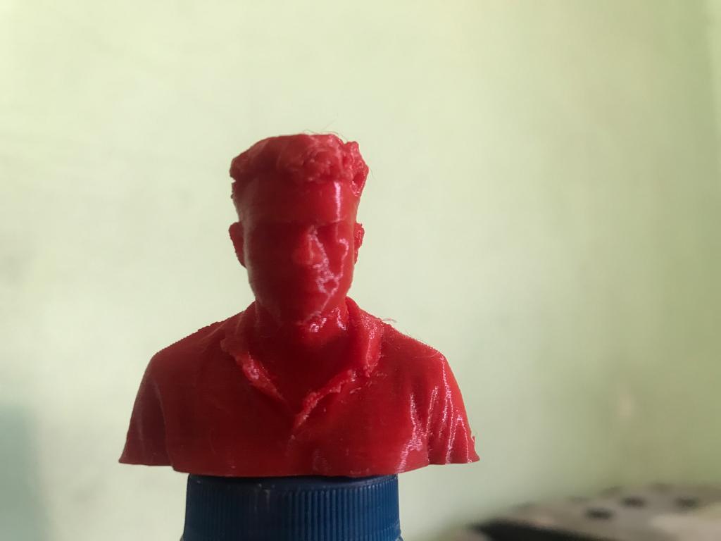
The scanner needs to interface with the software provided by 3d systems. We have downloaded the software and interface scanner with it. Then I Scanned All my teammates by keeping the scanner in hand and asked to rotate teammates about vertical 360 degrees.
The scanned object is modified in the Autodesk Meshmixer software. After modification, the part is printed in the 3D printer.
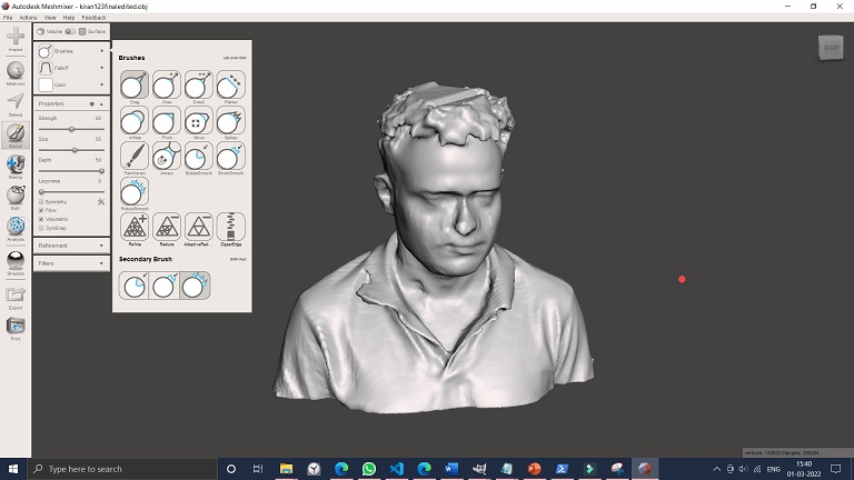
Then the corrected part is imported in the Fraktory tool for slicing and generate the G Code. Parameters used are 0.2 mm layer height and 60mm /min printing speed 60mm/min without any support for PLA material.
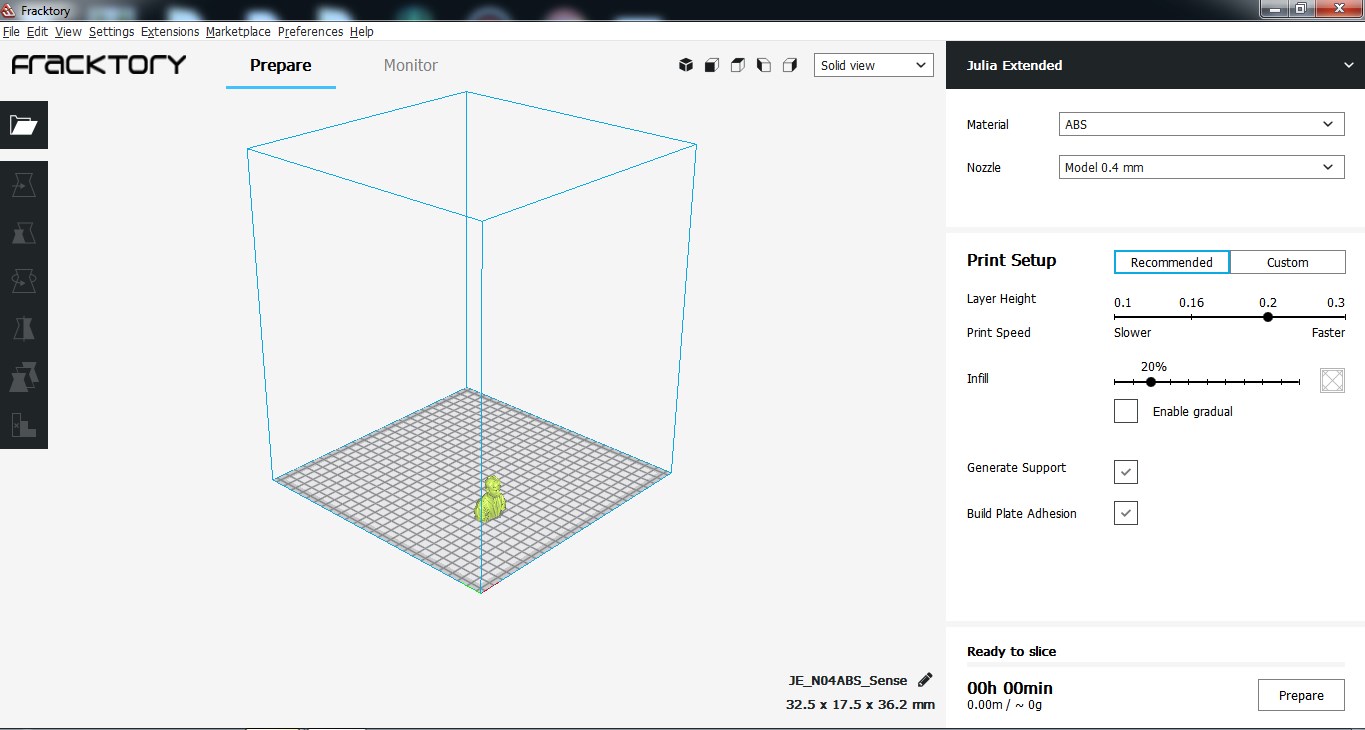
Final 3D model generated by 3D printed shown below.
I have also tried to design and print compliant Mechanisms.
Downloads
Editable Toroidal Ring Solidworks File.