Network and Communications
In this assigment I used the Fabduino PCB Board, designed in past assignments. Two PCB boards will be connected and communicate themself through RF signal.
I used two UHF RF modules at 433 MHz , for transmmiting and receiving data.
Modules can be found here. Link: https://www.amazon.ca/Transmitter-Receiver-Wireless-Modules-Raspberry/dp/B01N4WBL4V
Local vendor link: https://www.teslaelectronic.com.pe/producto/transmisor-y-receptor-de-rf-433mhz/
Reference link (information) https://lastminuteengineers.com/433mhz-rf-wireless-arduino-tutorial/
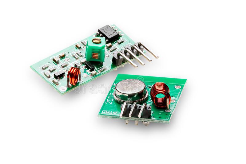
Specifications RF 433MHz Receiver
Frequency Range: 433.92 MHz
Modulation: ASK
Input Voltage: 5V
Price: $1 to $2
Specifications RF 433MHz Transmitter
Frequency Range: 433.92MHz
Input Voltage: 3-12V
Price: $1 to $2
Parts required in this assignment
Fabduino PCB Board
01 RF Module 433 MHz Transmitter
01 RF Module 433 MHz Receiver
Jumpers
So, I made the next circuit to test the RF link.
Schematic Circuit
I connected the TX to pin D2, and the RX to pin D3.
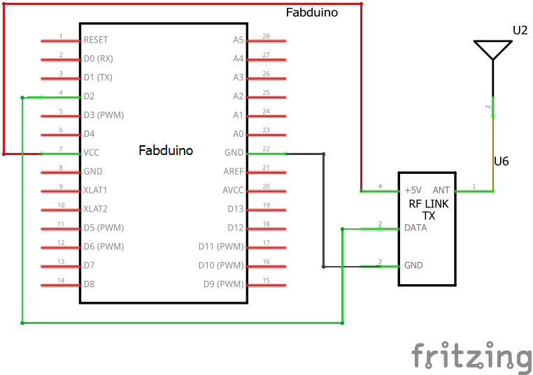
Tx circuit
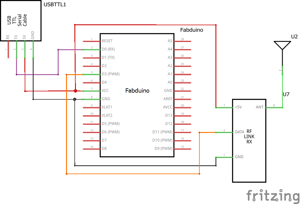
Rx Circuit
Programming PCB Boards
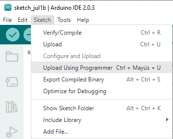
In the programming IDE we must select the board Arduino UNO.
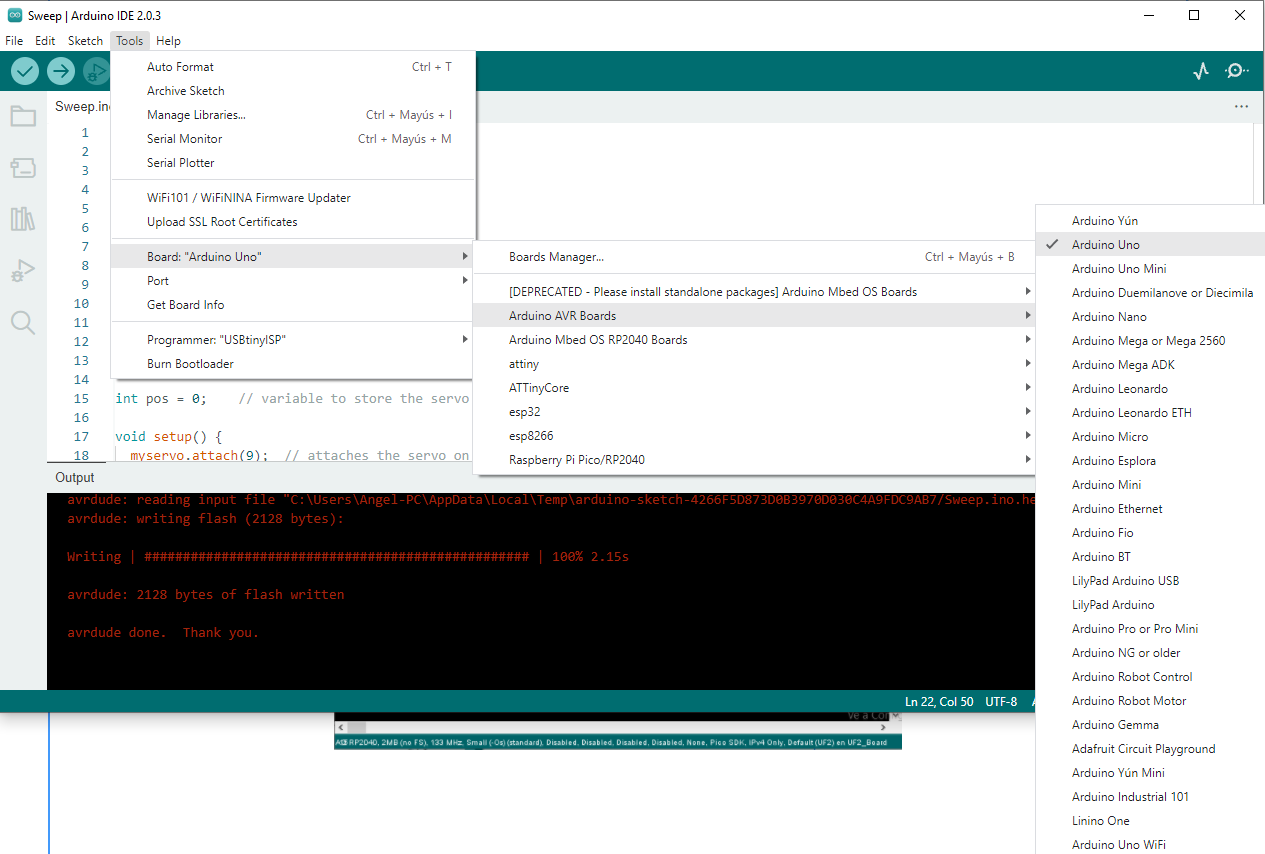
Select Upload Using Programmer for uploading the code
Fabduino and FabISP view
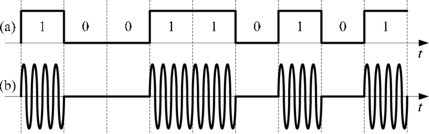
ASK Modulation
Amplitude-shift keying (ASK) is a form of amplitude modulation that represents digital data as variations in the amplitude of a carrier wave. In an ASK system, a symbol, representing one or more bits, is sent by transmitting a fixed-amplitude carrier wave at a fixed frequency for a specific time duration. For example, if each symbol represents a single bit, then the carrier signal could be transmitted at nominal amplitude when the input value is 1, but transmitted at reduced amplitude or not at all when the input value is 0.
Any digital modulation scheme uses a finite number of distinct signals to represent digital data. ASK uses a finite number of amplitudes, each assigned a unique pattern of binary digits. Usually, each amplitude encodes an equal number of bits. Each pattern of bits forms the symbol that is represented by the particular amplitude. The demodulator, which is designed specifically for the symbol-set used by the modulator, determines the amplitude of the received signal and maps it back to the symbol it represents, thus recovering the original data. Frequency and phase of the carrier are kept constant.
I used TinyRF-v1.7 library to test this circuit.
Code / Firmware for Transmitter
The transmitter code was located in TinyRf-1.7 library, Examples folder, Transmitter, Transmitter.ino
#include <RH_ASK.h>
#include <SPI.h> // Not actually used but needed to compileRH_ASK driver;
void setup()
{
Serial.begin(9600); // Debugging only
if (!driver.init())
Serial.println("init failed");
}void loop()
{
const char *msg = "Fab Academy!";
driver.send((uint8_t *)msg, strlen(msg));
driver.waitPacketSent();
delay(1000);
}
Code / Firmware for Receiver
The receiver code was located in TinyRf-1.7 library, Examples folder, Receiver, Receiver.ino
#include <RH_ASK.h>
#include <SPI.h> // Not actualy used but needed to compileRH_ASK driver;
void setup()
{
Serial.begin(9600); // Debugging only
if (!driver.init())
Serial.println("init failed");
}void loop()
{
uint8_t buf[12];
uint8_t buflen = sizeof(buf);
if (driver.recv(buf, &buflen)) // Non-blocking
{int i;
// Message with a good checksum received, dump it.
Serial.print("Message: ");
Serial.println((char*)buf);
}
}
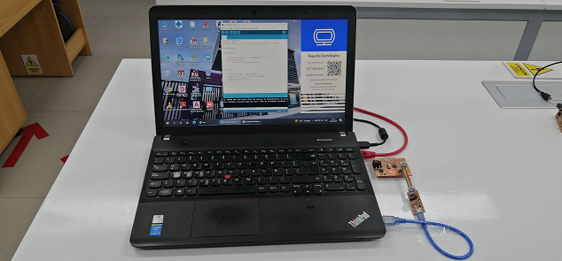
Testing
Code for transmitter PC board

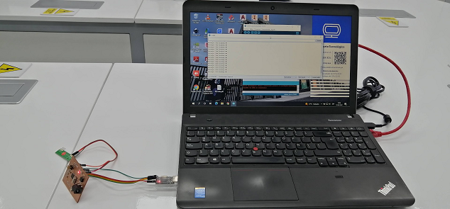
Transmitter side sending the message to receiver
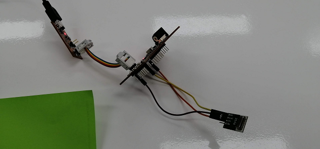
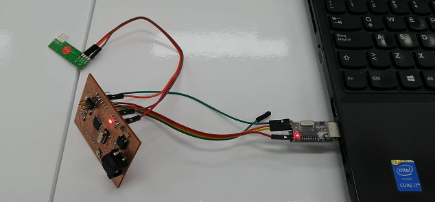
Connecting the RF receiver to Fabduino then to PC
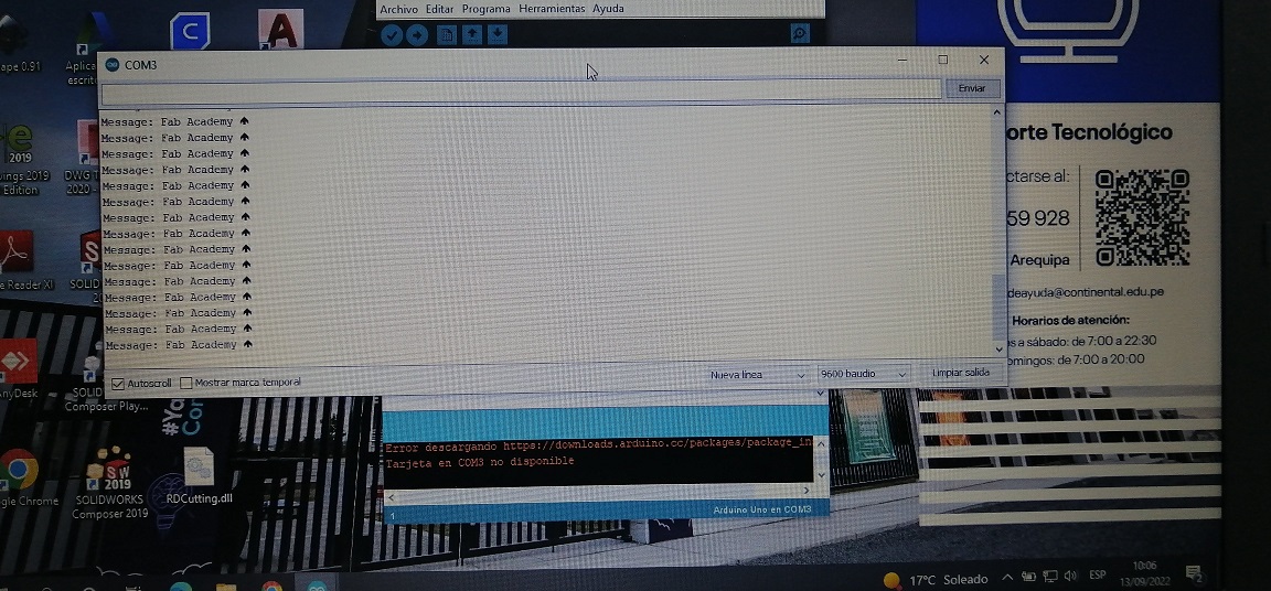
Serial Monitor showing the data received (message)
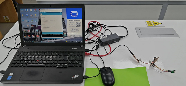
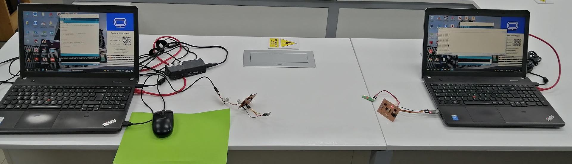
Both sides view: Transmitter and receiver
Download
Library TinyRF-v1.7 es here
Problems and solutions
- At first I had coverage problems, however, I solved it by placing a cable as an antenna and the signal gain improved considerably.
- You must be careful with special characters, that is why ASCII codes must be used.
Takeaways Assignment
- RF modules are widely used in electronic projects. They allow us to transmit information directly with good coverage, since they work in the UHF band.
- The ASK modulation that varies the amplitude of the carrier wave was chosen. It is a type of simple modulation.
- It was possible to transmit a string of characters to the receiver, but it can also be sent, for example, data from a sensor, measurements, voltage levels, etc.