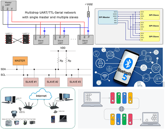
Network communications is used to transmit digital data typically between microcontrollers or the microcontroller and another external device. The best known are the wired protocols.
UART: Serial communication with two lines (RX and TX) between two devices.
I2C: Serial communication with two lines (SDA and SCK). master-slave architecture.
SPI: Full duplex serial communication. It uses four lines (CLK, MOSI, MISO, SS).
And the best known wireless communications to transmit voice and data without having to physically connect them through cables are.
Bluetooth: Wireless communication protocol between devices. ISM secure radio frequency of 2.4 GHz.
TCP IP: Internet communication standard, Transmission Control Protocol/Internet Protocol
I2C communication (Inter-integrated Circuit)
The name I2C comes from Inter-Integrated Circuit or inter-integrated circuits. Its version 1.0 was created in 1992 by Philips to communicate its microcontrollers with each other. Then a second 2.1 would come in 2000 and today it has become a standard (at 100 kbit/s, although it allows up to 3.4 Mbit/s maximum), in 2006 the Philips patent expired and it can now be used freely.
Currently it is widely used in the industry for communication, and it is also highly appreciated by makers for their projects to communicate different microcontrollers and peripherals integrated into an IC.
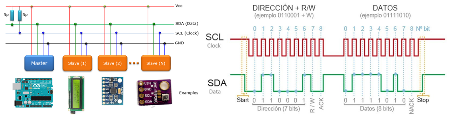
I2C is a well-known serial communication bus. It uses a synchronous communication protocol with only 2 channels (there is a third one, but it is coupled to reference or GND), in fact it is also known as TWI (Two Wire Interface):
- One for the clock or clock (SCL).
- Other for data (SDA).
Both are open-drain CMOS connections and require pull-up resistors.
This implies that the master and slave send data on the same cable or track, which is controlled by the first, which is the one that generates the clock signal. Each of the peripheral devices connected to the I2C bus will have a unique address assigned, in order to address the transmissions. But it is not necessary that the master always be the same (multimaestro), it is necessary that he is always the one who initiates the transfer.
OPERATION OF THE I2C BUS
In order to communicate with just one data wire, the I2C bus uses a wide frame (the format of the data sent). The communication consists of:
. 7 bits to the address of the slave device with which we want to communicate.
. A remaining bit indicates whether we want to send or receive information.
. A validation bit
. One or more bytes are the data sent or received from the slave.
. A validation bit.
With these 7 address bits it is possible to access 112 devices on the same bus (16 addresses of the 128 possible addresses are reserved for special uses).
This increase in the data sent (18 bits for every 8 bits of data) means that, in general, the speed of the I2C bus is reduced. The standard transmission speed is 100khz, with a high speed mode of 400khz.
The I2C standard defines other modes of operation, such as 8, 10, and 12-bit address sending, or transmission speeds of 1Mbit/s, 3.4Mbit/s, and 5Mbit/s.
The Atmega 328P on our board have hardware I2C support physically linked to certain pins. It is also possible to use any other group of pins as an I2C bus through software, but in this case the speed will be much lower.
The pins to which it is associated vary from one model to another, we always have to consult the corresponding pinout scheme in the datasheet.
The associated pins are PC4 pin 27 for SDA and PC5 pin 28 for SCK.
The Arduino IDE Standard provides the “Wire.h” library, which contains the necessary functions to control the embedded hardware.
Some of the basic functions are as follows:
Wire.begin() // Initialize the bus hardware
Wire.beginTransmission(address); //Start transmission
Wire. endTransmission(); // end the transmission
Wire. requestFrom(address,nBytes); // request a number of bytes from the slave at address
Wire.available(); // Detect if there is data pending to be read
Wire. write(); // Send a byte
Wire. read(); // Receive a byte
Wire. onReceive(handler); // Register a callback function when receiving data
Wire. onRequest(handler); // Register a callback function when requesting a data
There are other more advanced libraries than Wire.h to handle the I2C bus, such as I2Cdevlib, I2C library or libraries for circuits or cards implemented as for the PCF8574 circuit.
The basic circuit that we will use is the PCF8574, which is an expander of digital inputs and outputs (I/O) by I2C bus. It can be made by various manufacturers, as well as being available in ICs and modules.
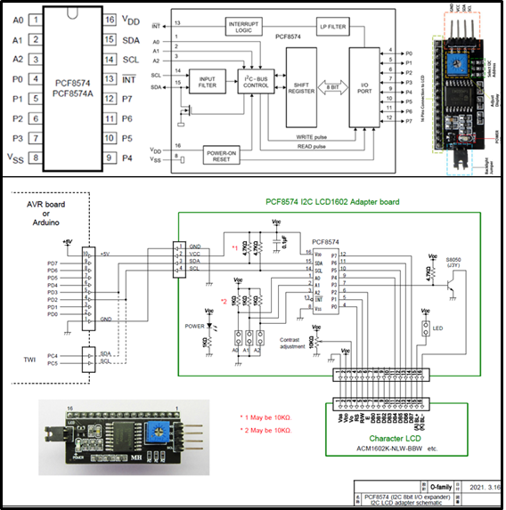
The PCF8574 pinout is simple, since it only includes 8 quasidirectional pins (P0-P7 where the chips to communicate are connected), and on the other hand you have the SDA and SCL that you must connect to the communication network, as well as VCC and GND to also power the module. And don't forget the three addressing pins A0, A1, A2 to choose which of the devices the communication is directed to.
You can get 8 possible addresses, that is, up to 8 devices to communicate with or using 8 modules to expand it up to 64 devices. The addresses (pins A0,A1,A2) will be:
000: address 0x20
001: address 0x21
010: address 0x22
011: address 0x23
100: address 0x24
101: address 0x25
110: address 0x26
111: address 0x27
Its connections, being open drain, can be used both as inputs and outputs.
The maximum current is 25mA when it acts as an output (sink, when the current flows from the PCF8574) and 300 µA (source, the current flows from the PCF8574).
The supply voltage is 2.5 and 6v. Stand-by consumption is very low, only 10 µA.
All the outputs have latches, to maintain the state without the need for external actions. You should only act when you want to change the state.
It supports interrupt (INT) by a special line to detect data without constantly monitoring.
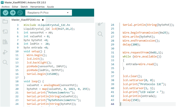
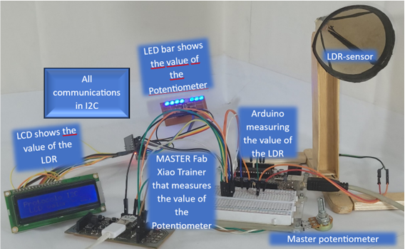
In order to demonstrate the communication we will use I2C communication, our Xiao RP2040 board will be the Master, with the other circuits being slaves.
We will take the value of a potentiometer (from 0-255) in the master and we will transmit its value through I2C to be able to see it in a bar of LEDs.
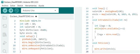
We will also work with an Arduino, first we will read the value of an LDR in an analog input, then the value read from the LDR is transmitted by I2C to the master, which in turn will display it on an LCD through I2C; in this way we can verify the write and read data on the I2C communication.
Here the Master and slave programs.
Master:
Slave:
The tests came out satisfactory, checking the I2C communication.
Video:
created with
Web Design Software .