INTERFACES AND APPLICATIONS PROGRAMMING
We are increasingly integrating with technologies, this week we will implement interfaces for hardware control.
Referring to hardware control, that which we can observe in robotics, in the control of industrial processes, in the control of houses known as home automation, the control of autonomous cars and other applications.
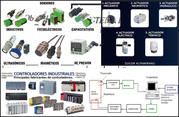
In this case we will talk a little more about process control, where the raw material is transformed into a finished product; These processes are made up of a set of elements such as reactors, distillers, heat exchangers, filters, mills, etc., related to each other, which offer output signals and receive input signals in the form of variables (temperature, pressure, level, position, volume etc).
It is important to highlight the fact that it is not necessary to know the internal workings, or how the various elements interact with each other, to characterize the system. For this, it is only necessary to know the relationship that exists between the input and the output of the process that it performs (black box principle). The most important aspect of a system or process is the knowledge of its dynamics, that is, how the output signal behaves when faced with a variation of the input signal.

In order to control these control systems we must develop treatments that determine the value of the output signal according to the input signal, we distinguish two general control topologies:
• Open loop systems. Where the output is not compared with the reference input (set point), therefore each input will correspond to a preset operation on the output signal as time elapses. It can then be ensured that the accuracy of the system depends largely on its calibration, although the presence of disturbances (unwanted signals) in the production chain will cause it not to fulfill the assigned function.
• Closed loop systems. The output signal has an effect on the control action, somewhat dependent on the output. This effect is called feedback.
The signal of the controlled variable must be fed back and compared with the reference input, after which a control signal is sent through the system, which will be proportional to the difference found between the input signal and the signal measured at the output ( error), with the aim of correcting the error or deviation that may exist.
The main advantage of closed-loop control systems is that the use of feedback makes the set less sensitive to external disturbances and variations in internal parameters than open-loop systems.
It is necessary to clarify certain terms such as:
- Reference input, Set point or SET POINT: Input variable in the controller that sets the desired value of the controlled variable. It can be set manually, automatically, or scheduled.
- Controlled Variable: Within the control loop, it is the variable to be controlled (temperature, level, flow, etc. as required by the process), this signal is captured through the transmitter sensor and originates a feedback signal.
- Transmitter Sensor: Captures the process variable (or controlled variable) through the primary element (or sensor) and converts it into a standard transmission signal (for example, 4mA to 20mA).
- Manipulated Variable: It is the variable that is used to maintain the controlled variable at its set point. Another serious definition is the amount of the process varied by the final control element.
- Final Control Element: Receives the signal from the controller and modifies the manipulated variable. The control valve is the typical final element that regulates the flow rate of the fluid.
- Disturbance or disorder: Any signal that tends to affect or alter the output of the system, that is to say that the controlled variable has deviated from the control point.
In industry, these disturbances are the cause of the need to control the process because if there were no alterations in the process, control would not be required since the operating conditions of the process would prevail without changing its variables.
- Controller: is the "brain" of the control system.
In any closed control system, 3 basic operations are performed, starting with:
1.- Measurement (M) The measurement of the controlled variable is generally done through the combination of sensor and transmitter.
2.- Decision (D) Based on the measurement, the controller decides what to do to keep the controlled variable at the desired value (at its set point).
3.- Action (A) As a result of the controller's decision, an action must be taken in
In some systems, decision-making is simple, while in others it is more complex depending on the control action that is decided to be used.
Controlled systems based on electronics are the current controllers and are constantly evolving, they are based on the use of microprocessors, microcontrollers and personal or industrial computers.
These controllers make the decision based on a control action, which is the method chosen to correct the final element and compensate for the error, these can be.
ON/OFF control ON/OFF control with hysteresis.
Proportional Action Integral Action
Derivative Action. Action with Neural Networks.
Action by FUZZY logic.
As well as combinations of these, for example, the PID that is most used in the industry.
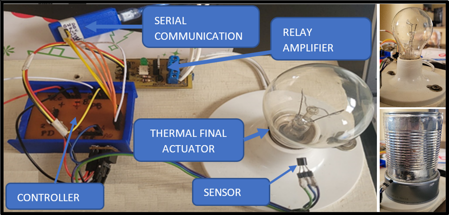
To begin with, we will implement a homemade thermal system which we will control from an interface that can show us the degrees Celsius that we want at any moment.
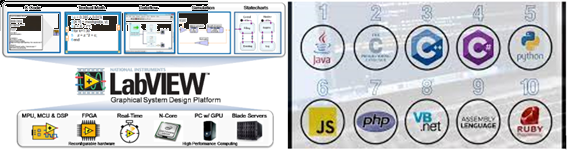
We will work with LabVIEW (acronym for Laboratory Virtual Instrument Engineering Workbench), it offers a graphical programming approach that helps to visualize every aspect of the application that is being developed, it has the possibility of accessing different ports of our computers like any other software that is command line programming such as Python, C++, Java, etc.
To connect with our hardware (developed card) from LabView we will use serial communication, which is the most viable between our computers and cards with these Microchip microcontrollers.
To open the serial port and communicate with the Attmega 328P we will do a first practice sending quantities and representing them in LEDs as shown.
Interface:

Now that we were able to communicate our card with Labview, we proceed to develop the control program for our system.
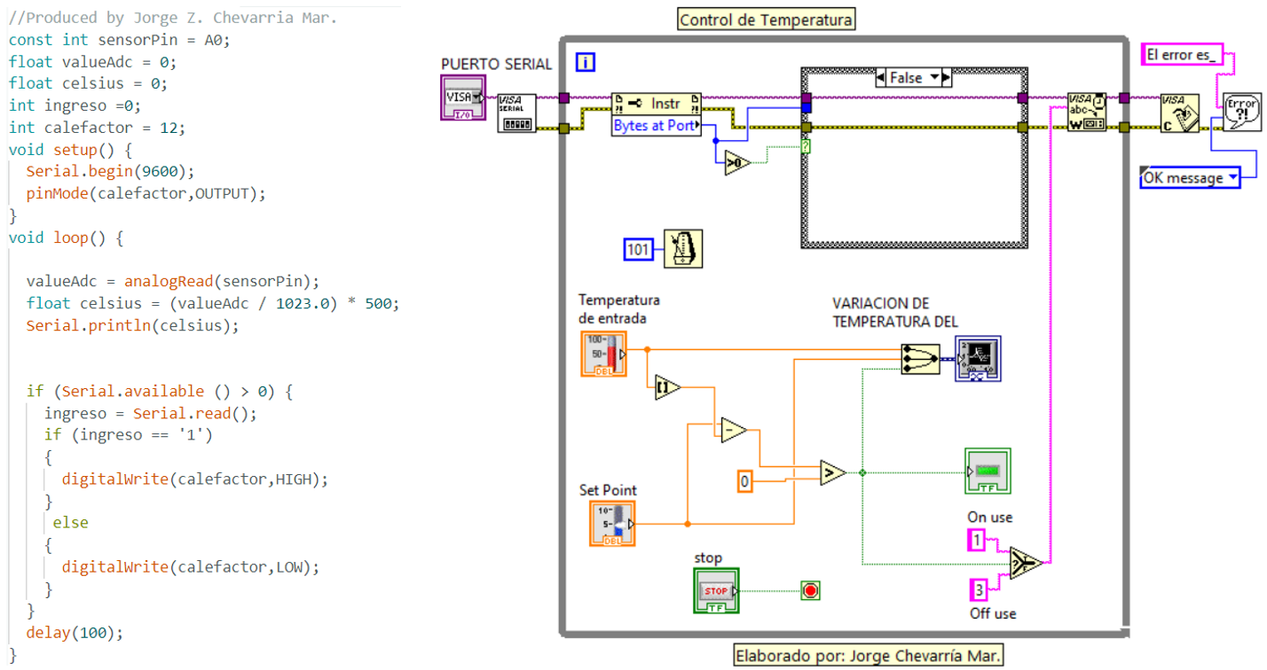
The proof is correct.
INTERFACE FROM THE CELLPHONE
To control our temperature system, we will use an App for Android, which is the cell phone operating system, and with the help of the Bluetooth communications protocol, specially designed for low-power devices that require short-range transmission and based on low-cost transceivers.
Bluetooth can transmit information in many interesting and innovative ways. The most daily links are with devices that we use at home, with a smartphone for example we can control many equipment that we have at home and for research we have many development boards such as Arduino.
By using serial Bluetooth signals, the phone controls the equipment as seamlessly as if the two devices had a hardware connection (via cables).
With the development of applications for cell phones with Bluetooth, they transformed the cell phone into a communications terminal. Communications are carried out by radio frequency so the devices do not have to be aligned and can even be in separate rooms if the transmission power is sufficient. These devices are classified as "Class 1", "Class 2" or "Class 3" in reference to their transmission power, with devices in one class being fully compatible with those in the others.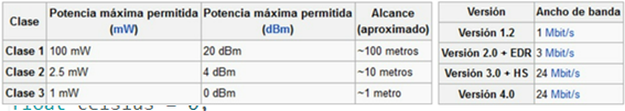
For communication with bluetooth, many architectures were presented, but the simplest is to make the Bluetooth modules HC 05 and HC 06.
These modules allow us to connect our projects with a smartphone, cell phone, development boards like Arduino or a PC wirelessly (Bluetooth), with the ease of operation of a serial port. The transmission is done completely transparently to the programmer, so it is connected directly to the serial pins of our preferred microcontroller (respecting the voltage levels, since the module is powered by 3.3V). All module parameters can be set by AT commands. The board also includes a 3.3V regulator, which allows the module to be powered with a voltage between 3.6V - 6V. This module is the ideal complement for our robotics, home automation and remote control projects with Arduino, PIC, Raspberry PI, ESP8266, ESP32, STM32, etc.
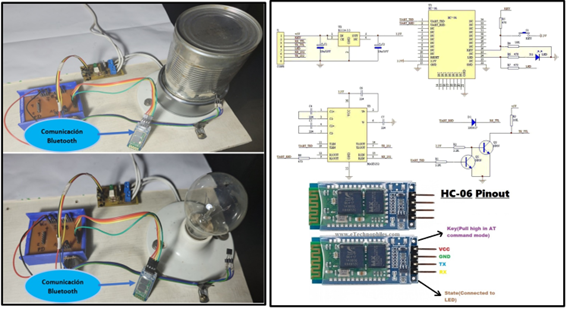
Bluetooth communication occurs between two types of devices: a master and a slave. If our objective is to connect our project to an android cell phone, we can use either an HC-06 or an HC-05 module configured as a slave, that is, prepared to listen for connection requests.
This module complies with the specifications of the Bluetooth 2.0 standard that is perfectly compatible with Android cell phones or smartphones.
TECHNICAL SPECIFICATIONS
• Operating voltage: 3.6V - 6V DC
• Current consumption: 50mA
•Bluetooth: V2.0+EDR
• Frequency: 2.4GHz ISM Band
• Modulation: GFSK (Gaussian Frequency Shift Keying)
• Transmission power: 4dBm, Class 2
• Sensitivity: -84dBm at 0.1% BER
• Range 10 meters
• Communication interface: Serial TTL
• Transmission speed: 1200bps up to 1.3Mbps
• Default baud rate: 38400,8,1,n.
• Security: Authentication and encryption
• Working temperature: -20C to +75C
• Android compatible
• Dimensions: 37*16mm
• Weight: 3.6 grams
There are many mobile applications that interact with bluethoot
Now I will develop an interface to control the proposed thermal system from a mobile application, in this case we will use bluetooth electronics that you can review at this link https://www.keuwl.com/apps/bluetoothelectronics/.
First we download the application for the cell phone (bluetooth electronics) and set up our program in a new window (panel 9) together we develop a program for the Atmega 328 of our card, then we link our HC05 via bluetooth, and we run our program and test the functioning.
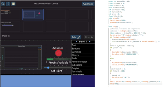
We tested the controller and it came out great.
created with
Static Website Generator .