19. Project Development
# Goal:
Tracking the progress of the final project.
# Overview and Progression:
My final project is to create a solar panel cleaning robot. This robot depends on two rotating microfiber brushes to clean the panels without scratching their surface. These brushes are connected to 3D-printed tires and two continuous rotation servo motors. Thus, the robot will move along the solar panel while the cleaing process is taking place. Also, I included an ultrasonic sensor and RTC as input devices to read the distance and time, respectively.
1. Electronics
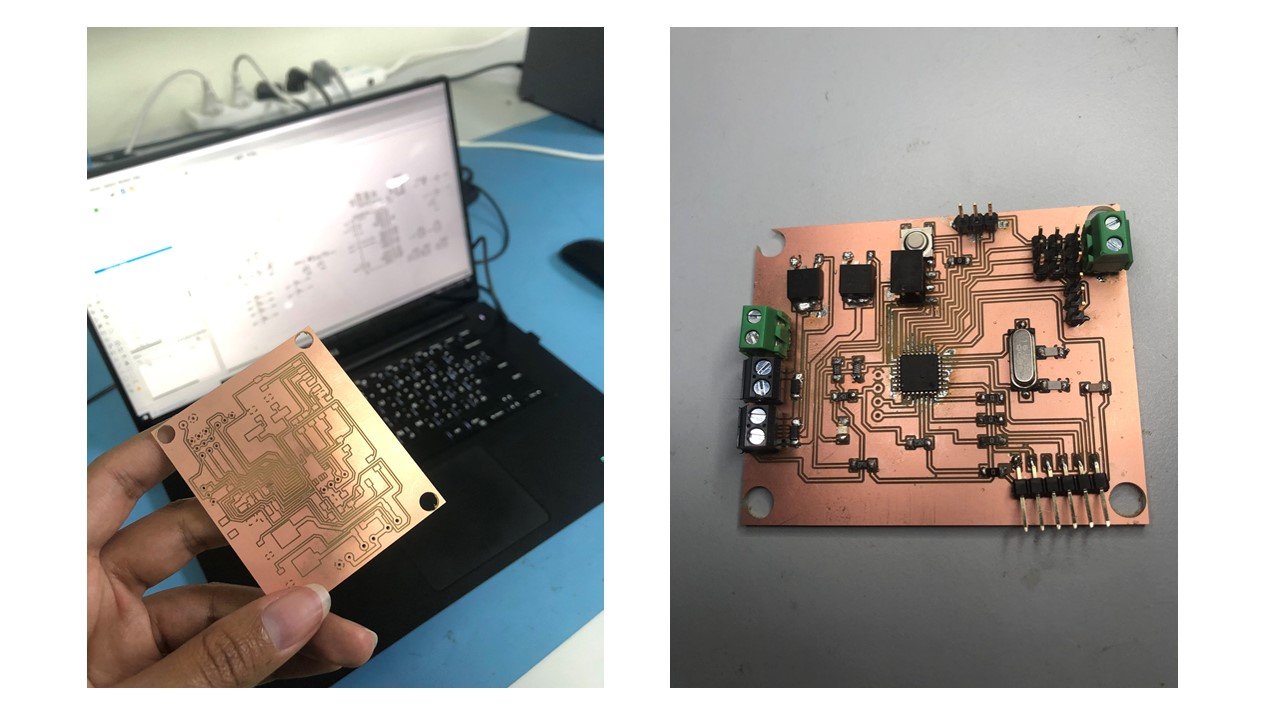
a. Designing:
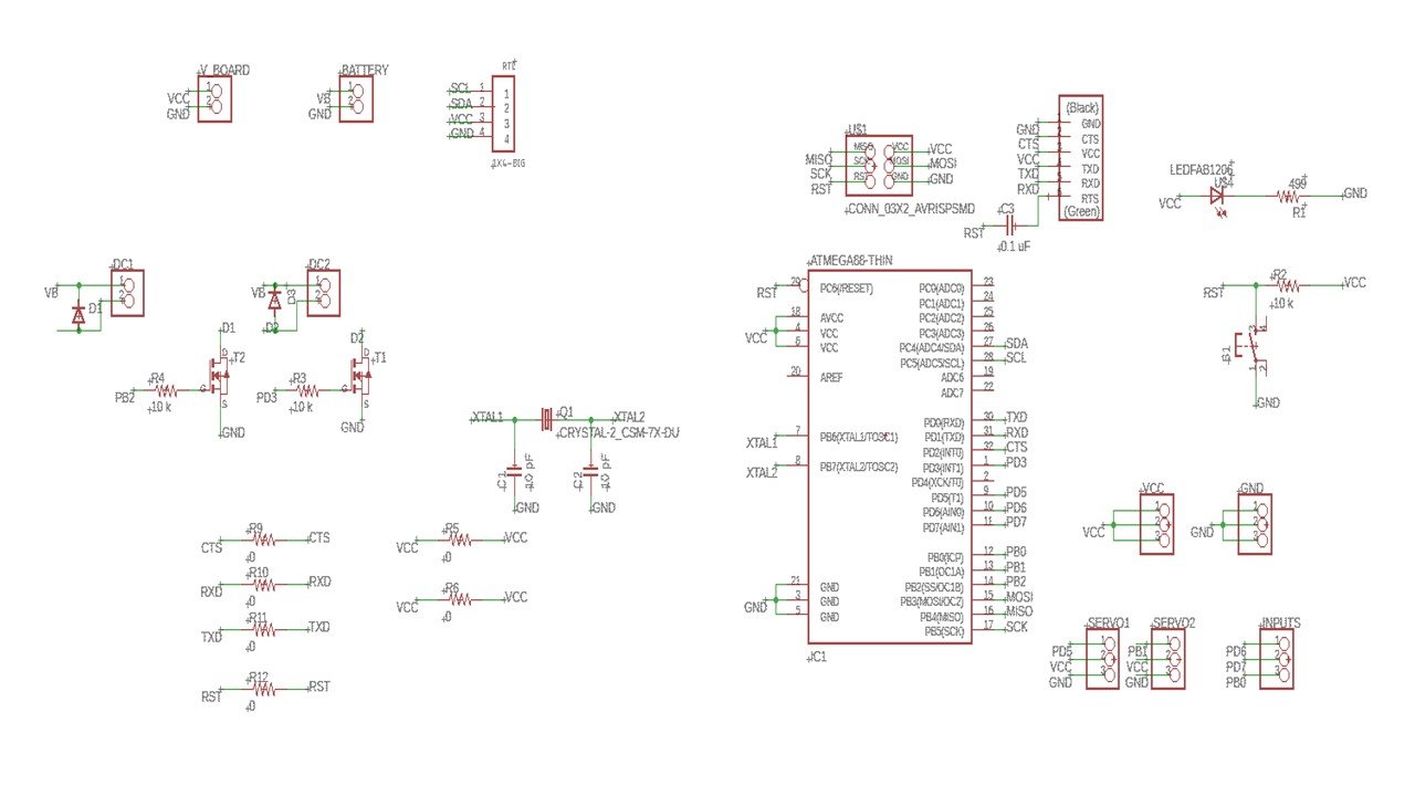
During the Output Devices week, I designed an Ardiuno Uno-like board using ATmega328 microcontroller on Eagle software. This board can control output devices:two DC motors and two continous rotation servo motor, and input devices: a real-time clock (RTC) and two ultrasonic sensors.
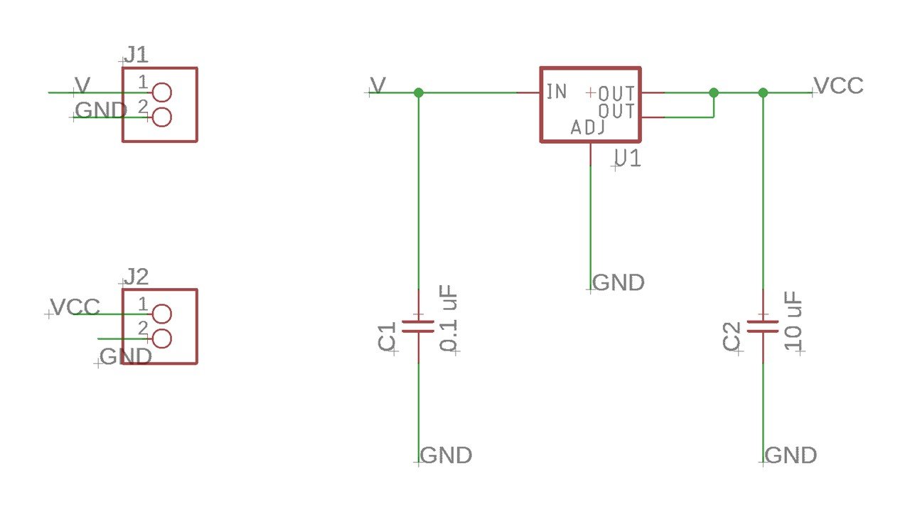
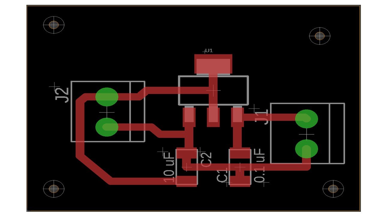
Then, I created another board to regulate the battery voltage using a regulator.
b. Fabrication:
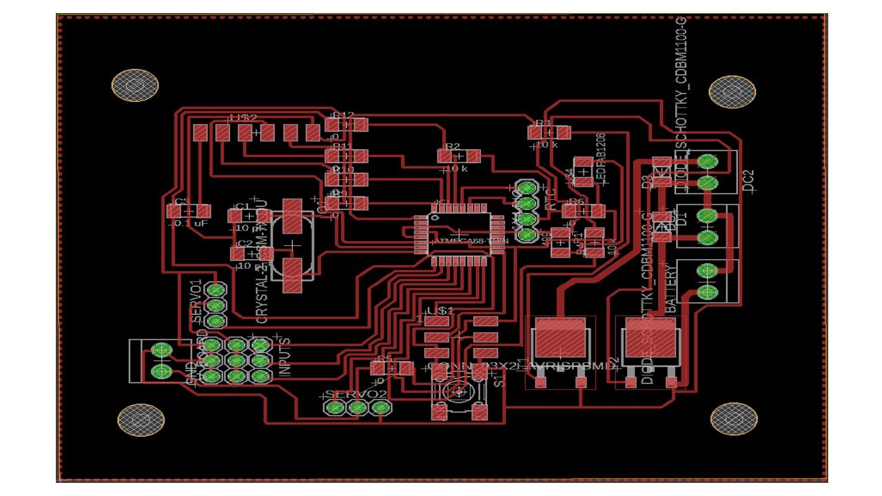
I used FlatCAM software and followed the steps written in electronics design week to generate the CNC code for the outline and border, which the Renold SMR-20 CNC machine can understand. To create the holes, I follow the steps in the Output Devices week. Then, I follow the steps electronics production week to mill the PCB using the Renold SMR-20 CNC machine. After soldering, the PCB is shown below.
c. Programmming:
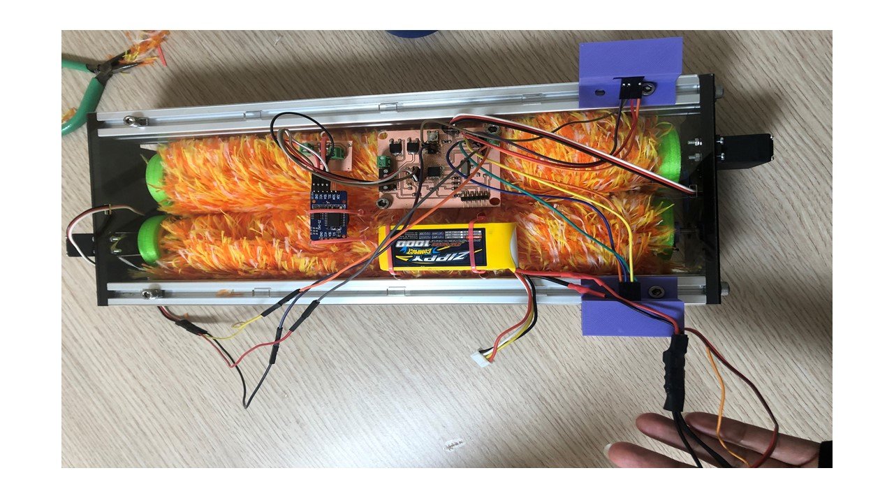
After burning bootloader using USBtinyISP, I uploaded the following code to the ATmega328 board. Then, I connected the input and output devices as follow:
1- The first servo motor: GND, VCC, PD5 (pin 13).
2- The second servo motor: GND, VCC, PB1 (pin 9).
4- The RTC: GND, VCC, SCL to pin PC5, SDA to pin PC4.
5- The first ultrasonic sensor: GND, VCC, PD6 (pin 6), PD7 (pin 7).
6- The second ultrasonic sensor: GND, VCC, PB0 (pin 8), PB3 (pin 11).
Then, I connected the battery to the regulator board and the main board since these devices draw considerable power.The code can be found in the final project page.
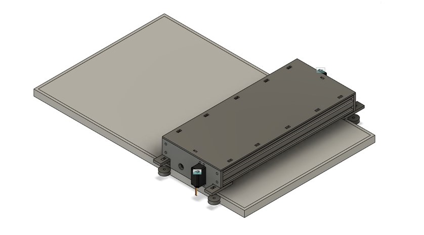
2. Computer-aided Design
I 3D-designed the robot using Fusion 360 as shown below.
1. What tasks have been completed, and what tasks remain?
The completed tasks are:
1- Fabrication of the ATmega328 board.
2- Connection of the servo motors to the ATmega328 board and ensure it was operating.
3- Connection of a real-time clock (RTC) to the ATmega328 board.
4- Connection of an Ultrasonic sensor to the ATmega328 board.
5- Design the two side plates and wheels.
6- Cut the 2060 aluminum profiles and the microfiber brushes to the panel dimensions.
The uncompleted tasks are:
1- 3D print the wheels using TPE and PLA filaments.
2- Create the two side plates and the robot cover using lase cutting and acrylic.
3- Assembly of the cleaning robot.
4- Program the code to control the robot using the PCB and Arduino IDE.
2. What's working? what's not?
The working part are:
1- The ATmega328 board.
2- The continous rotation servo motor.
3- The real-time clock (RTC).
4- The ultrasonic sensors.
The not working part are:
1- The 3D printed wheels.
2- The main code of the robot.
3. What questions need to be resolved?
How to control the robot and its sensors?
How to ensure that the robot will move in straight line?
What are the dimenions of the wheels?
4. What will happen when?
I wasn't able to finish the project on time. However, I presented my final project. The uncompleted parts are cutting the cover of the robot and ensuring the robot operates correctly.
5. What have you learned?
During the building of this robot, I developed all the learned skills learned throughout the diploma. These skills are 3D designing, 3D printing, electronics design, electronics production, laser cutting, and machine building.