This week, we entered the world of electronics. It wasn't difficult, as I had previously dealt with the machine and designed and manufactured PCB's.
It must be asserted that the electronics is the main part to any engineering project. Therefore, it is necessary to learn the basic principles and try in depth in all electronic topics.
Learning:
- Group Assignment
- Line Test / Traces
- Line Test / Outline
- Warm up
- Surfacing
- Individual Assignment
-
Roland monoFab SRM-20
-
In-Circuit Programmer
-
Soldering
-
Programming
-
Silhouette Cameo 4 Vinyl Cutter
-
In-Circuit Programmer
-
Roland monoFab SRM-20

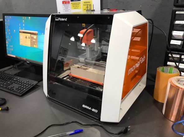
As a small milling machine, the SRM-20 offers compact size and powerful functionality at an affordable price. Production of realistic parts and prototypes is made simple and convenient with a device that fits into any office, home, or classroom environment.
The SRM-20 portable milling machine can mill a broad range of materials, including modeling wax, chemical wood, foam, acrylic, poly acetate, ABS and PC board.
Group Assignments
This assignment is about characterize the design rules for our in-house PCB production process.
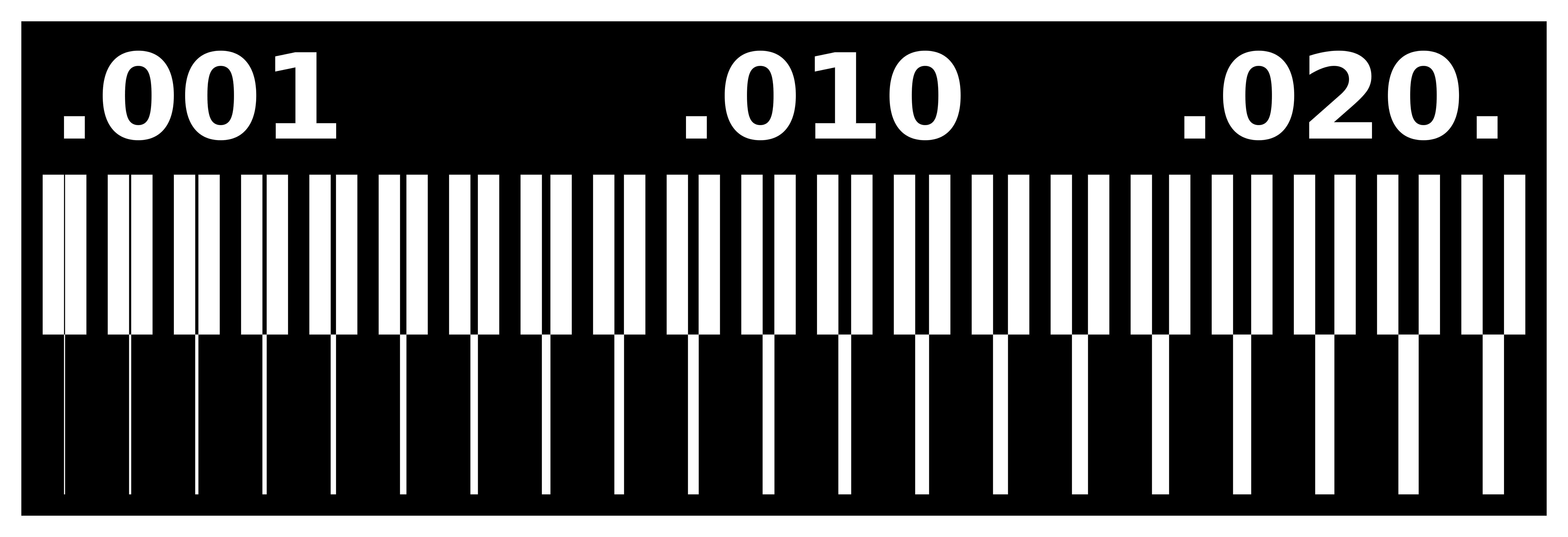
Line Test Traces
To start milling, we searched on Line Test design to calibrate the speeds and adjustments necessary to make the lines of our boards well. And we found from previous year Lorena Delgado from FabLab Leon.
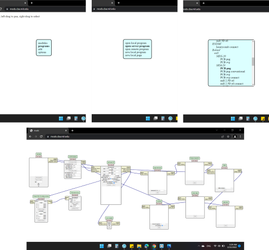
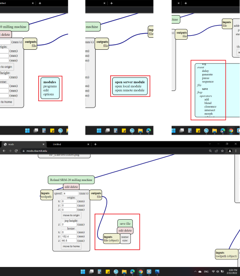
We used a CAM software Fab Modules that is online to set the correct settings for the machine and the tool path of the milling process.
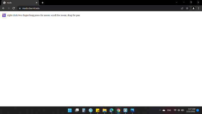
The steps to upload png is Programs > Open Server Program > Machines / Roland / SRM-20 / PCB png
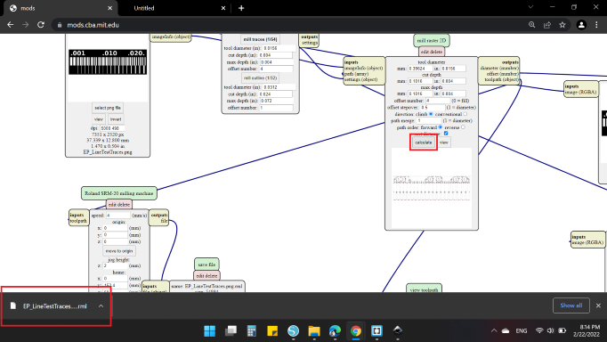
First, I clicked on "select png file" and I chose the image "EP_LineTestTraces" that I want to cut the traces of it.
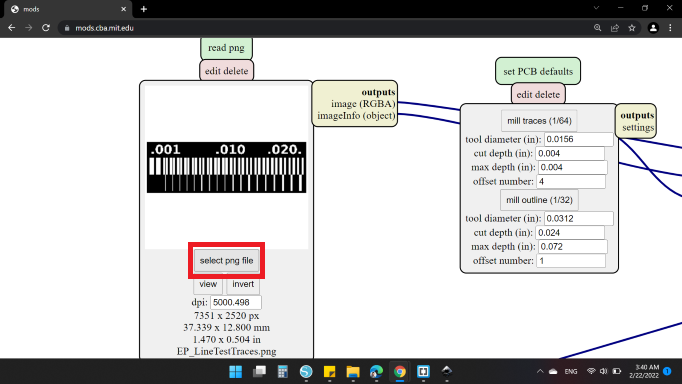
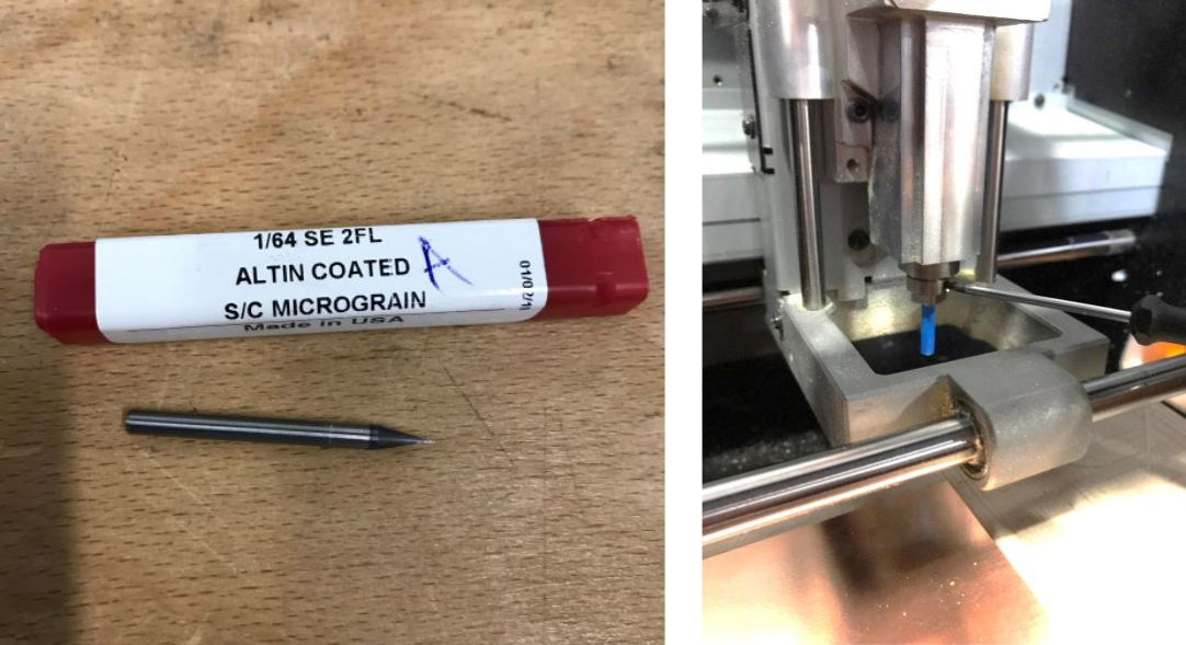
Then I selected the process to be "mill traces (1/64)".
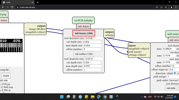
Next, the cut settings
- Tool Diameter
- mm: 0.39624 / in: 0.0156
- Cut Depth
- mm: 0.1016 / in: 0.004
-
Max Depth
- mm: 0.1016 / in: 0.004
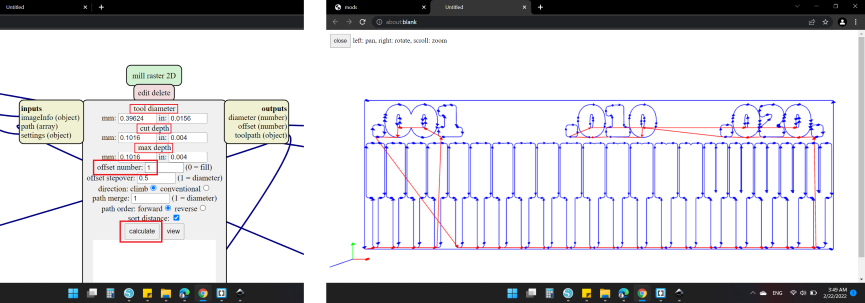
For the offset number, I set to be 1 to check that there is no overlap in cut lines, and clicked "calculate".
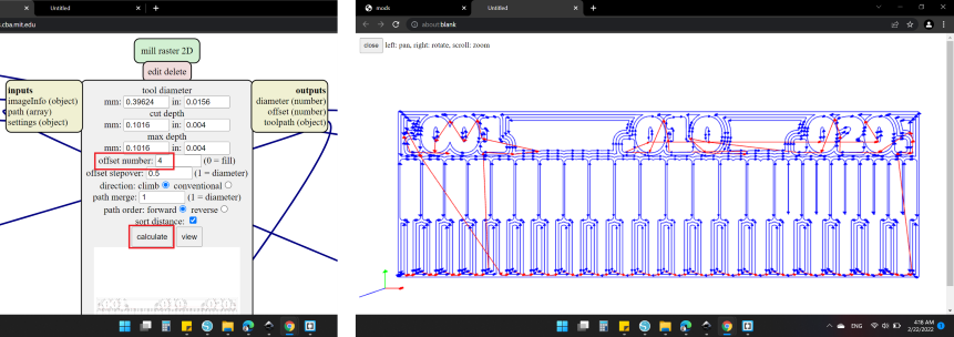
Then I changed it to 4.
After done with the offset, I moved to the next block. Here I set the speed to be 4 mm/s and the origin is zero for all directions .
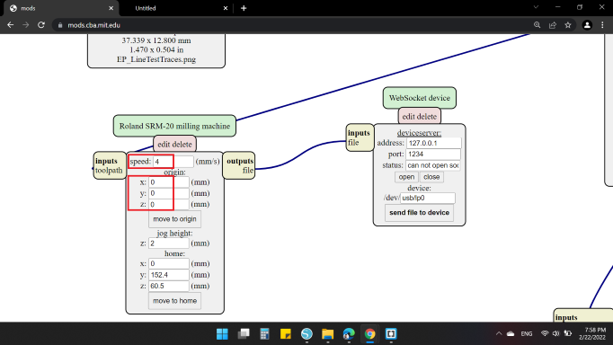
In order to save the file, I insert additional block "save file" from Modules > Open Server module > File / Save.
Finally, I went back to "Calculate" block and clicked on it. Then automatically the file was downloaded by .rml format.
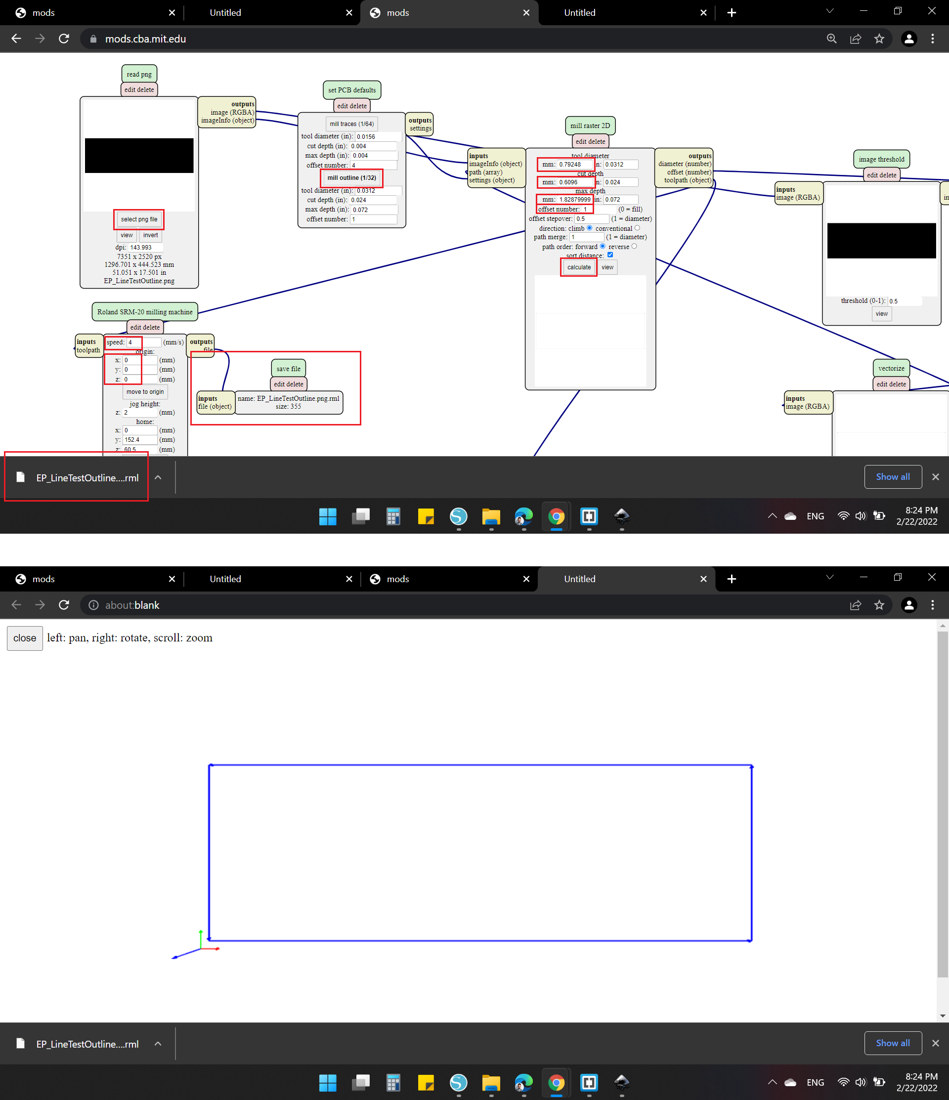
Line Test Outline
For the Outline cut, the same steps only "mill outline (1/32)" rather than mill traces.

Warm up
After the two files are ready, now it's time to use the Roland SRM-20!
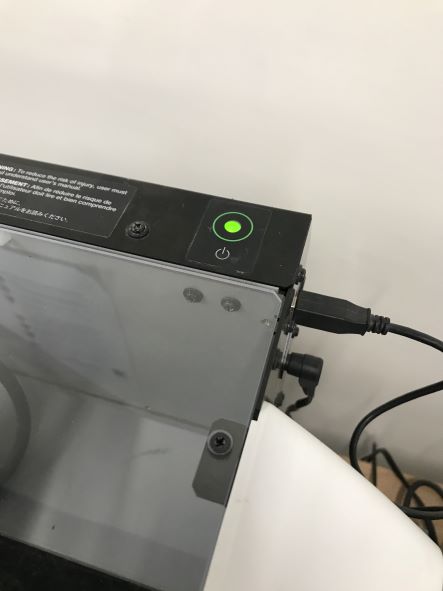
At first, I operated the machine by pressed On/Off button (It glows green, when the machine is running), ensured that the Cable has to be connected to USB port and the Power Supply is connect too.
Before starting any process, we must warm up the machine when the machine is first set up, or when the machine is not used for a prolonged period.
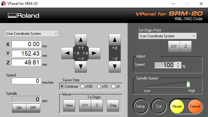
First, start the VPanel for SRM-20 software.
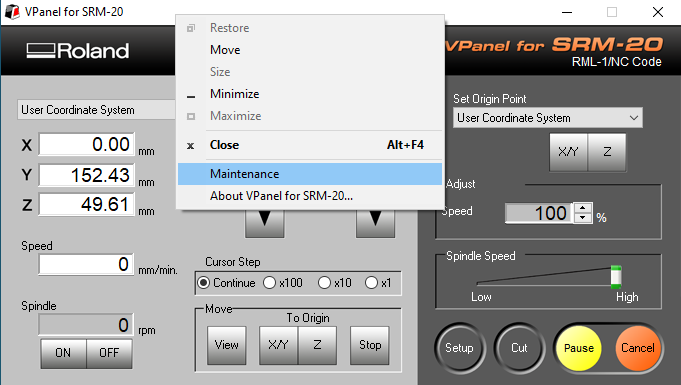
Then, click at the upper left of a screen, and select "Maintenance".
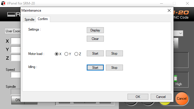
Click "Confirm" tab, then select [Start] of "Idling". (Required time: Approx. 10 minutes).
Surfacing
After the machine finish, It must from time to time work on leveling "surfacing" the plate.
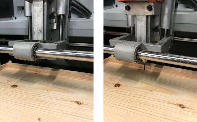
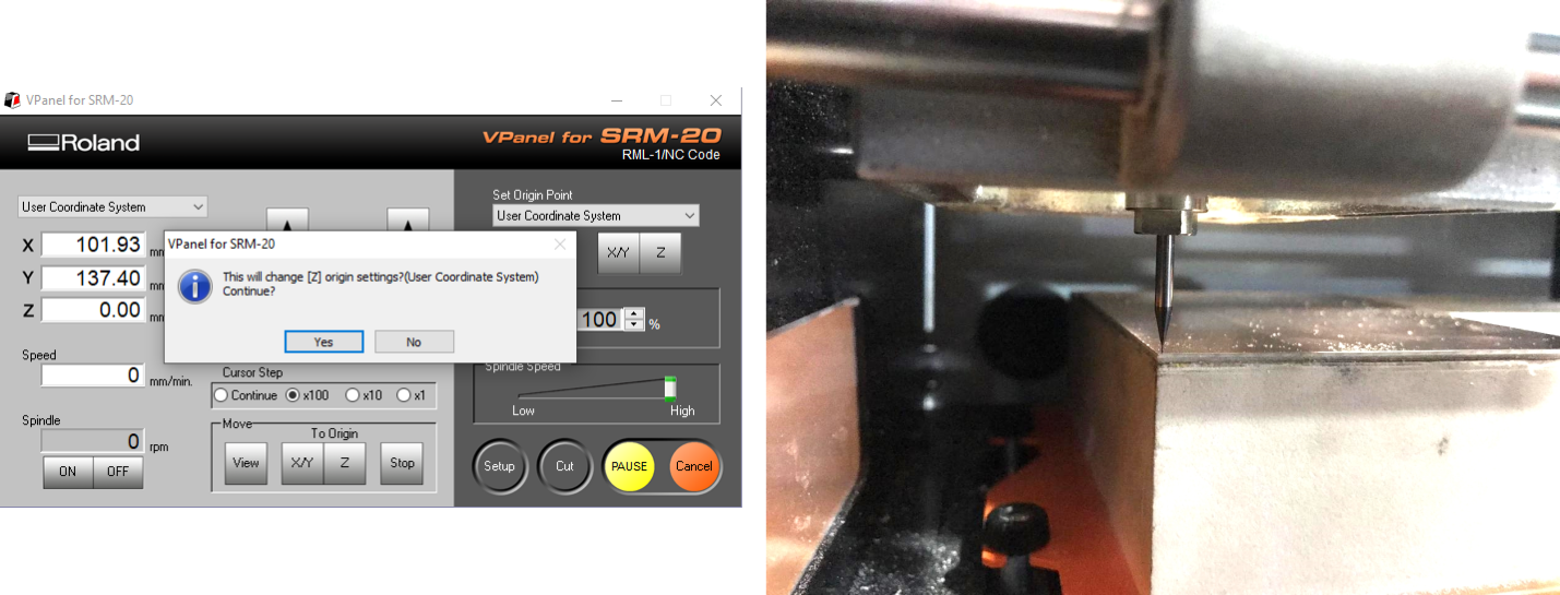
Before running the machine to any cut, you must set the origin point (X, Y, Z).
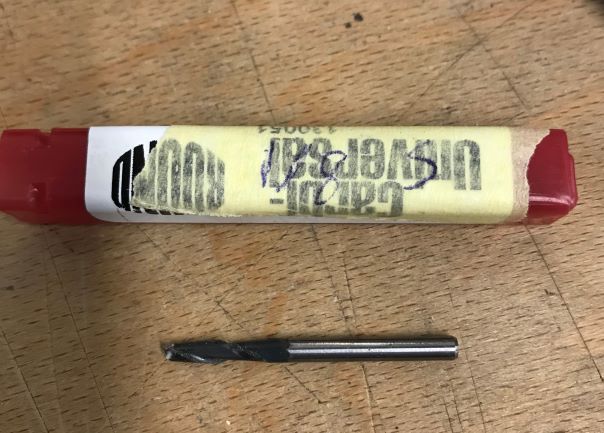
Initially I installed a 1/8" end mill.
I approximated the tip of the cutting tool to the surface of the material as much as possible, then I loosen the set screw to drop the cutting tool onto the surface, finally tighten the cutting tool in place again with the set screw.
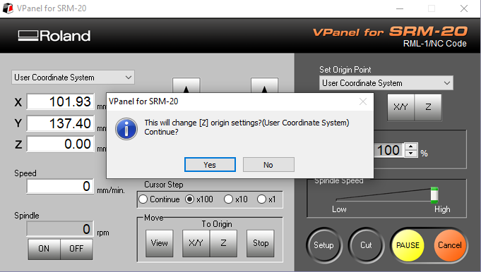
Then, I selected [Z] of set origin point.
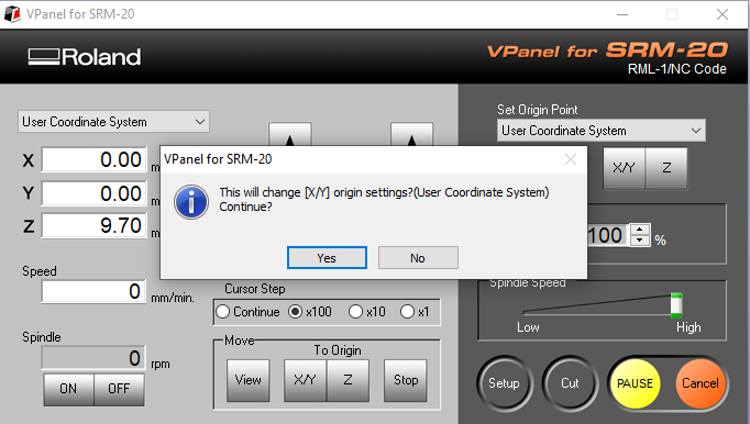
The same way to the [X/Y], moving to the desired position, and select [X/Y].
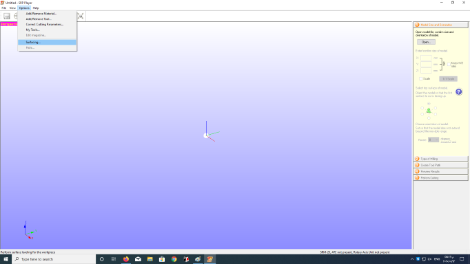
After the [X][Y][Z] are set to the origin point, I used another software called  to surfacing. I clicked on "Options" then "Surfacing".
On the dialog that appears, I modified leveling cutting range, depth, and other settings.
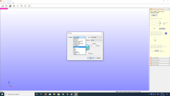
- Material: Wood (hard)
- Tool: 1/8 inch Square
- Orbit Direction: Up Cut
- Depth: 0 mm
- X: 203.2 mm
- Y: 152.4 mm
When done, I clicked "OK" and another dialog appears.
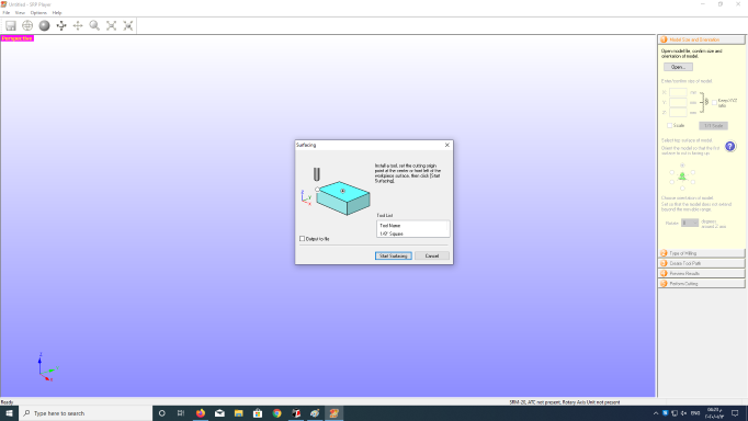
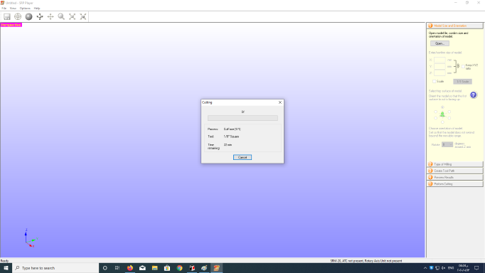
Here make sure that the desired tool and origin position are correctly set up. When I clicked on "Start Surfacing" the machine operate and start leveling the plate.
Making the Line Test
Now let's get back to the two designs of the PCB to manufacture, I clicked on "view" to brings the plate to the front and lifts the tool.

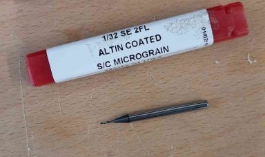
Then I installed end mill 1/64".
Next, I set the zero for [X][Y][Z] as I did before.
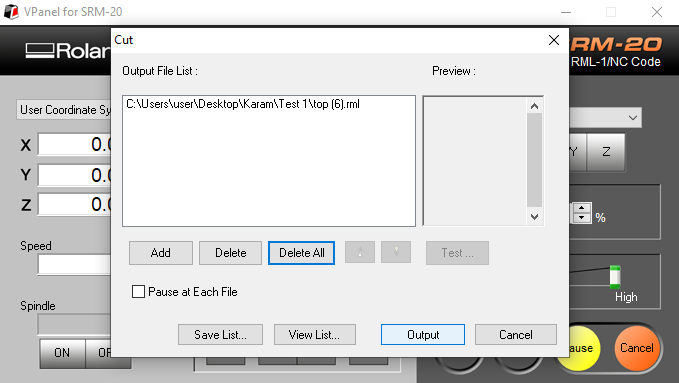
To cut, I clicked on "cut" to choose the file "EP_LineTestTraces".
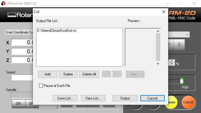
But before, I deleted any existing files, then clicked on "Add" and choose the traces file, and the machine operated directly by click on "Output".
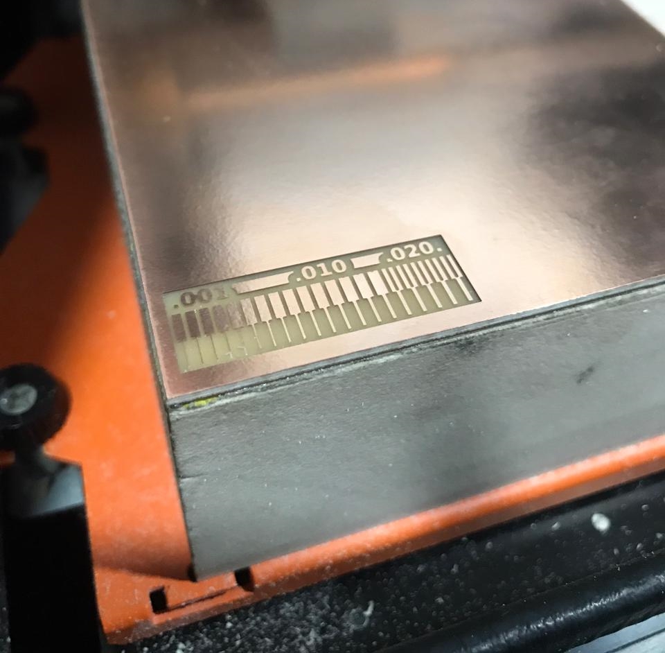
After a few minutes, maybe more, the machine finished cutting. It looks so clean and shine.
Next, I installed the end mill 1/32" to cut the outline job.
Then as before, zero [X][Y] and set a new zero for the [Z]. last run the job!
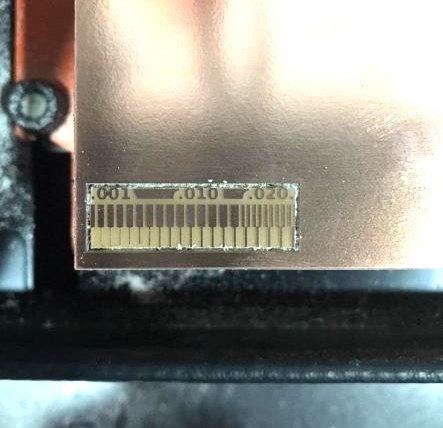
Here's the result.
Individual Assignments
Roland monoFab SRM-20
In-Circuit Programmer
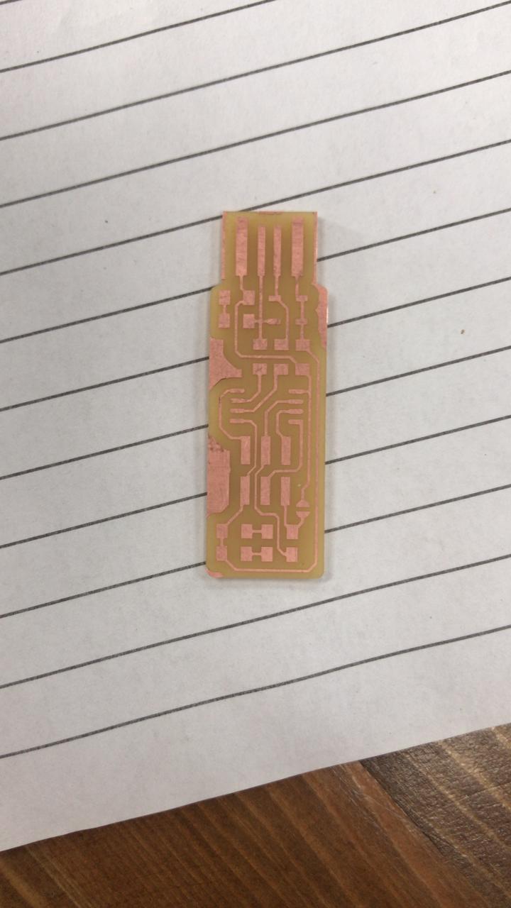
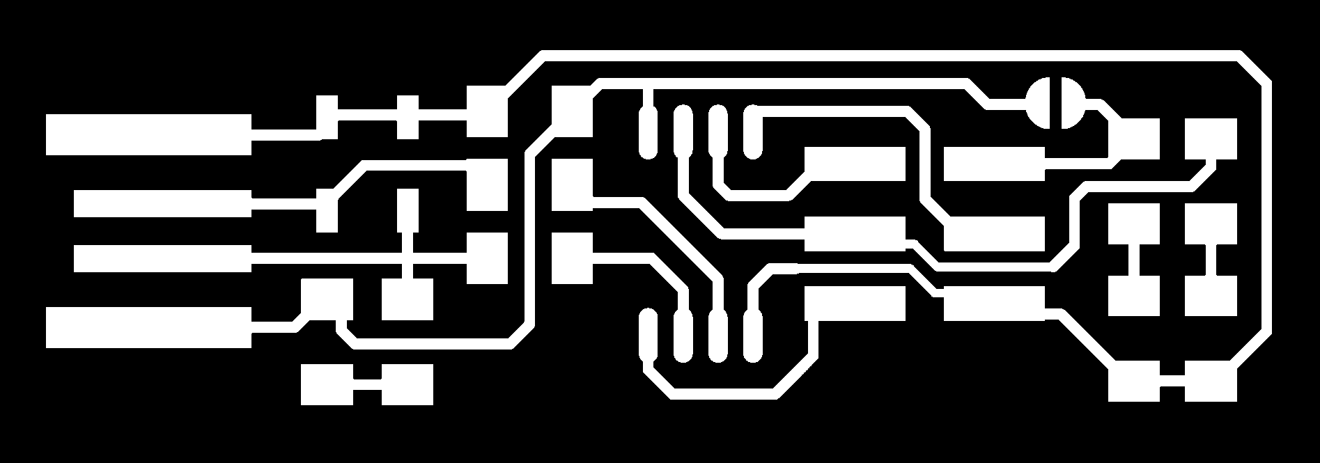
For the Individual Assignment, I decided to make FabTinyISP boards
I came back to Lorena Delgado to get the image.


As a same steps we did for the Line Test in Fab Mods, here I did the same for both Mill Traces & Outline.
And here's the results.
Soldering
Now it's time to solder the components.
Soldering is used to form a permanent connection between electronic components and it's a metallic "glue" that holds the parts together and forms a connection that allows electrical current to flow.
This isn't the first time I've soldering, but every time I struggle with handling small components and burning myself or the components! Soldering is not so easy, but it is fun.
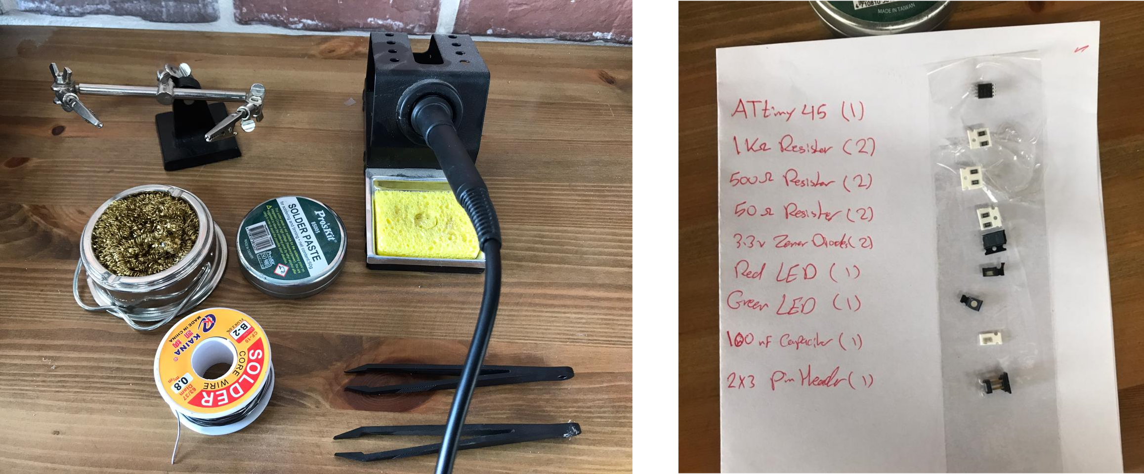
First before start soldering, you need to prepare your workplace and your soldering parts and the electronics components.
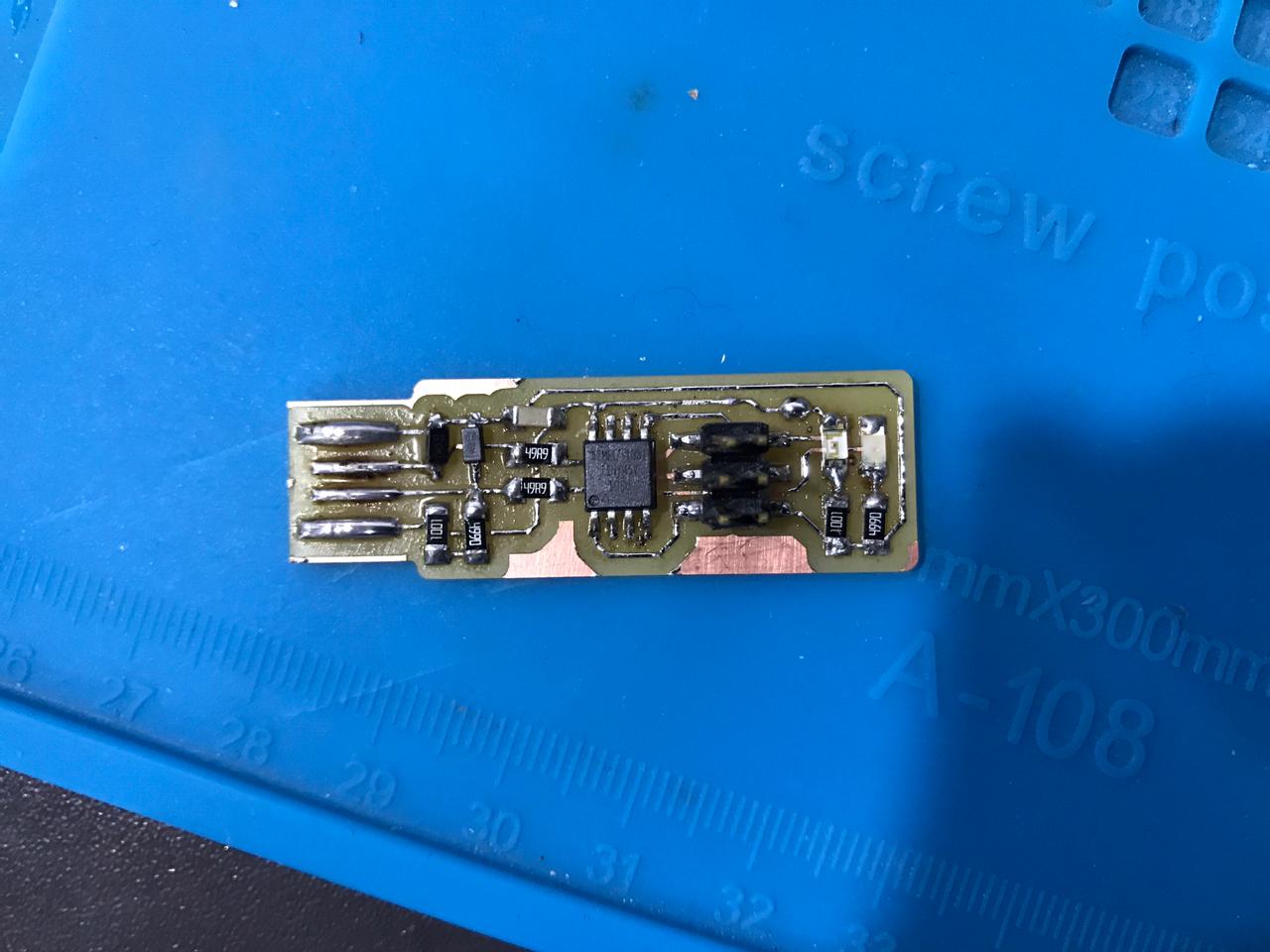
After a time of soldering and heating with the rising fumes, here's the board :).
Programming
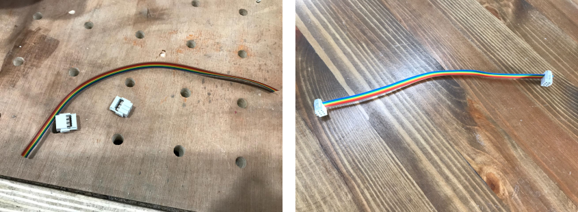
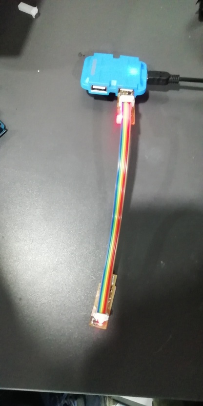
Before I start, I made an ISP connector 2x3.
To program the ISP programmer, follow the steps below 👇
- Step 1: Download “Atmel AVR Toolchain for Windows” ZIP file. Extract it in certain place that you specify.
- Step 2: Then edit the "make" file and name your programmer.
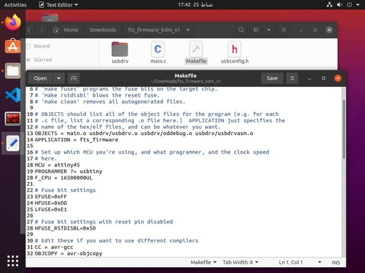
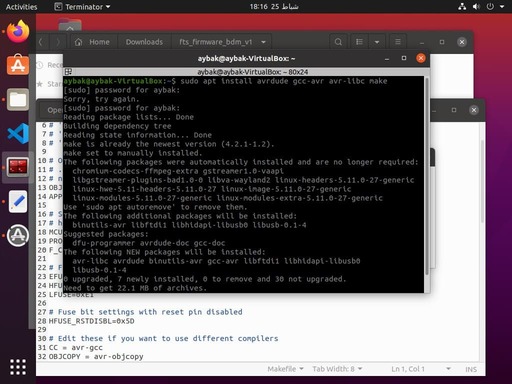
- Step 3: Now close the make file and install the "avrdude". Enter the following command, followed by your password when prompted: sudo apt install avrdude gcc-avr avr-libc make
- Step 4: Now connect the programmer to your board and make sure that you are in the correct orientation
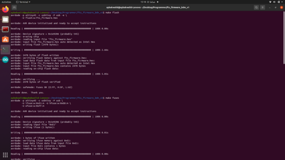
- Step 5: make This will build the hex file that will get programmed onto the ATtiny45. When the command completes, you should now have a file called fts_firmware.hex.butt before exute this command go to the fts_firmware_bdm_v1 file using cd command v
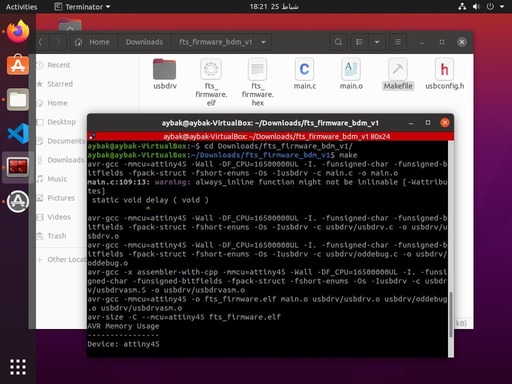
- Step 6: make flash This will erase the target chip, and program its flash memory with the contents of the .hex file you built before
- Step 7: make fuses This will set up all of the fuses except the one that disables the reset pin
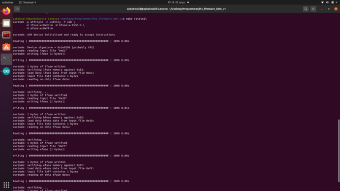
- Step 8: make rstdisbl his does the same thing as the make fuses command, but this time it's going to include that reset disable bit as well.
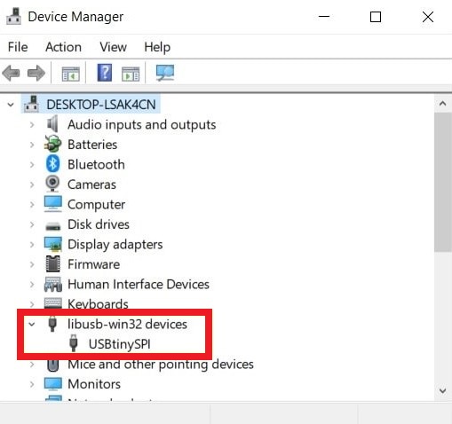
Also, Check that the programmer is listed it “Device Manager”
Silhouette Cameo 4 Vinyl Cutter
In-Circuit Programmer
I wanted to try something new for me, which is cutting the PCB on a Vinyl Cutting machine.
As steps, it's less than the milling machine, but it's hard to cut without ruining it!
As I mentioned last week about the Silhouette Studio, really it's wonderful in trace bitmap automatically and can do some CAD too in design workspace.
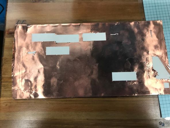
Before I worked on my design, I did a test of the "Copper Foil Roll" material to ensure the proper cut parameters as the previous week.
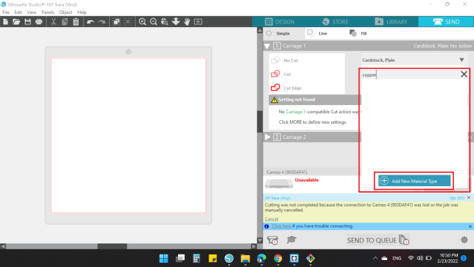
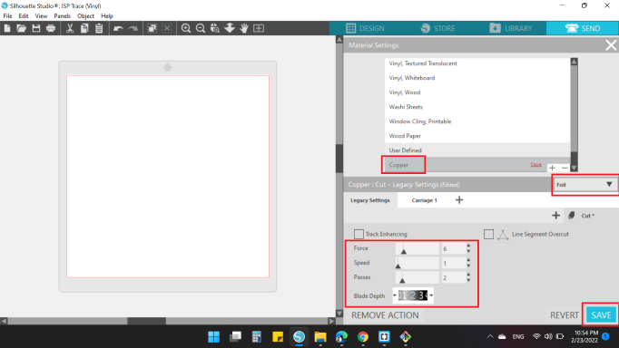
So, I clicked on SEND option at the right top of the software.
Then I searched for the name of a substance that indicates copper, unfortunately I did not find anything.
So, I decided to added to the list.
To have a point to start, I searched on internet for a copper cut parameters, and I found this website.
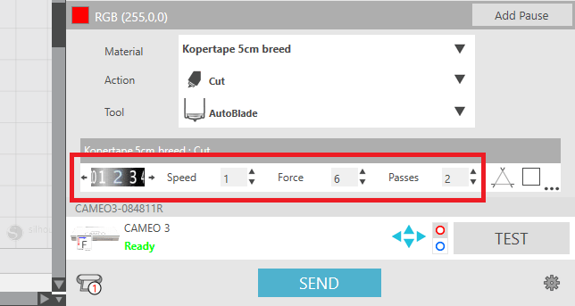
- Blade Depth = 2
- Passes = 2
- Force = 6
- Speed = 1
So, I puted those cutting settings to my new material "copper".
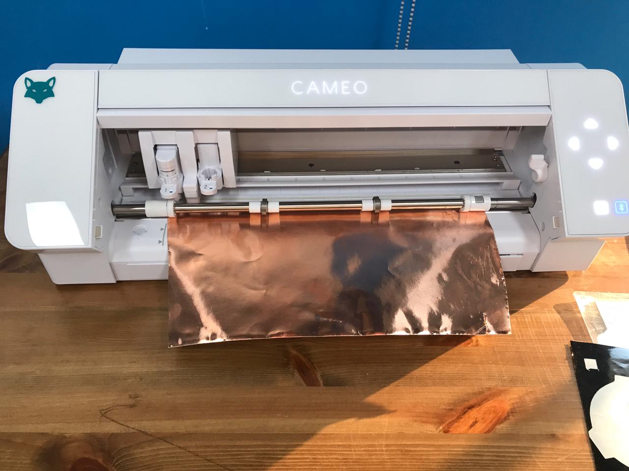
Then, inserted the copper sheet to the machine.
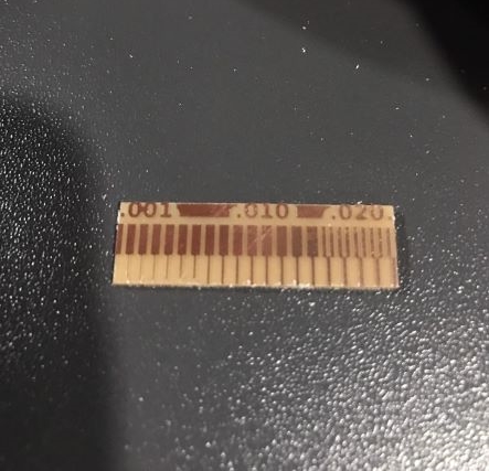
Finally, I clicked on TEST option, and the results was good.
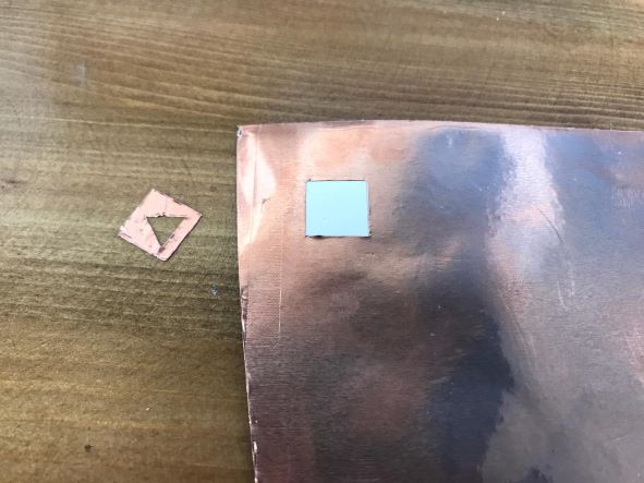
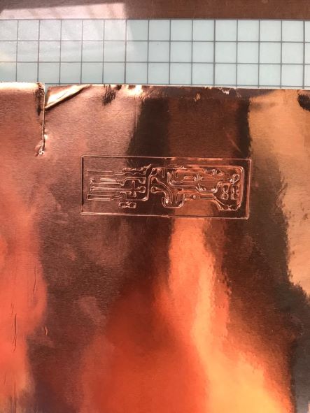
I inserted the image EP_FabTinyISPTrace into the workspace.
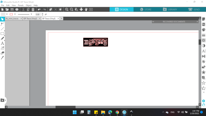
With the same cut parameters settings, I cutted my design. Unfortunately, it wasn't good at all 😞
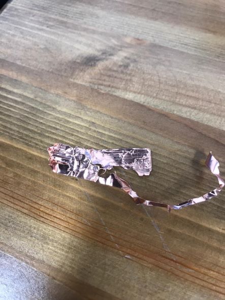
Tried to change some settings:
- Blade Depth = 3
- Passes = 1
- Force = 15
- Speed = 1
Also, not good either.
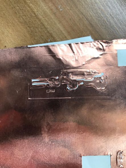
I changed the settings several times and all of them failed.
The last tried was the closest thing with the cutting parameters:
- Blade Depth = 2
- Passes = 1
- Force = 10
- Speed = 1
I decided to try again in the coming weeks so the design is suitable for the vinyl machine.
You can download my files here: