From this week we started working with lab machines.
We Have two types of assignments; one Group Assignments and one Individual Assignments.
As We are in Computer Controlled Cutting week, so Laser & Vinyl Cutter's are our target.
Learning:
-
Full Spectrum Muse Laser Cutter
- Group Assignment
-
Individual Assignment
-
Parametric Construction Kit
-
Living Hinge
-
Laser Cut 3D Model
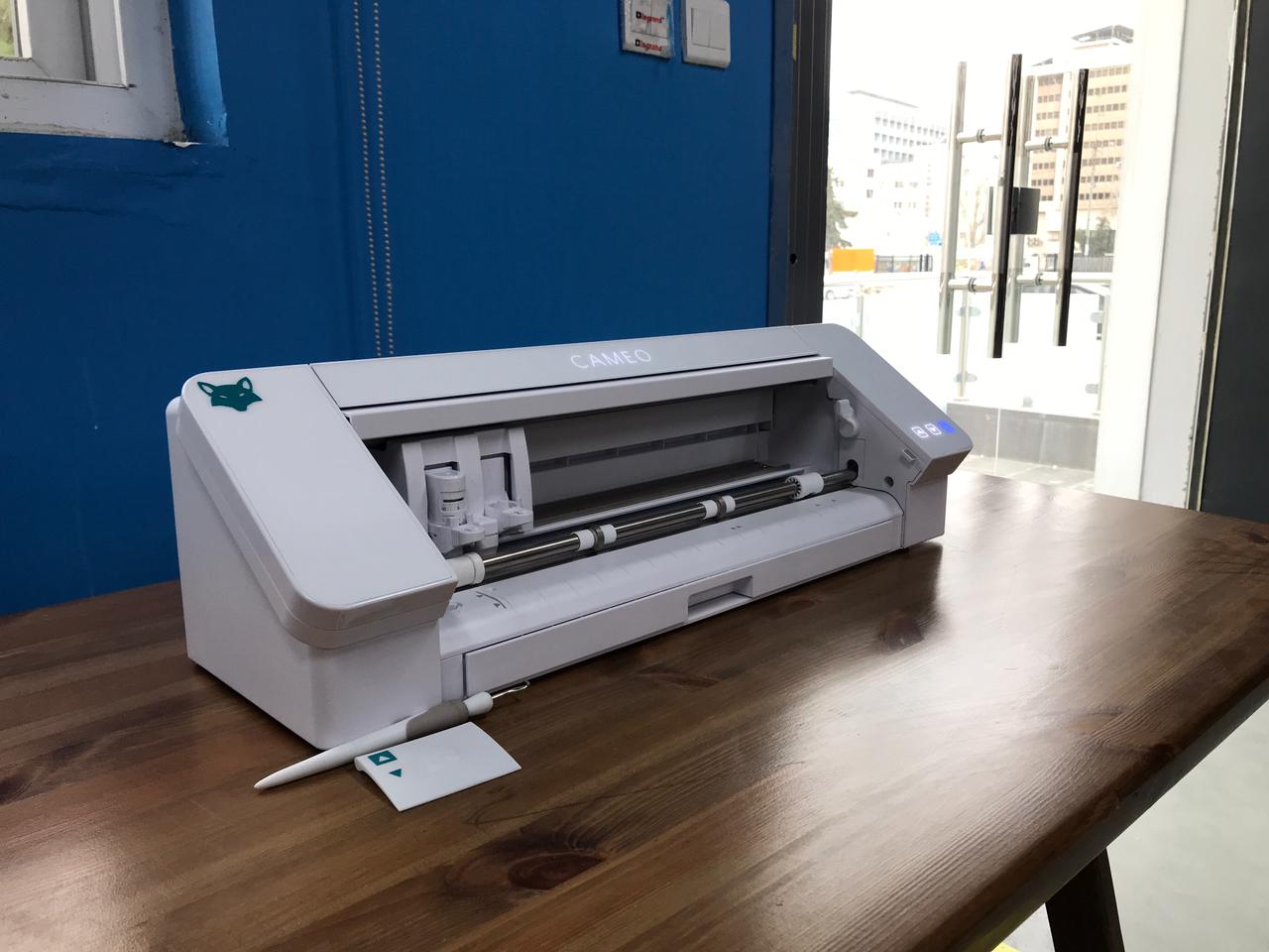
- Silhouette Cameo 4 Vinyl Cutter
-
Individual Assignment
-
Vinyl Cutter
-
Individual Assignment

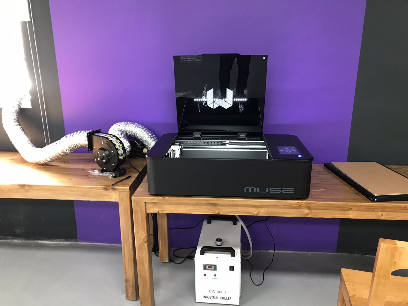
Muse is the best desktop laser on the market and keeps getting better with 3D camera features, autofocus, LCD touchscreen functions and the powerful, yet easy-to-use, self-hosted browser based RetinaEngrave v3.0 laser control and design software. With working area: 508mm x 305mm x 63.5mm.
It is a fast machine, which allows you to perform projects very quickly and combine different materials.
Group Assignments
This assignment is about characterizing the laser cutter's focus, power, speed and kerf.
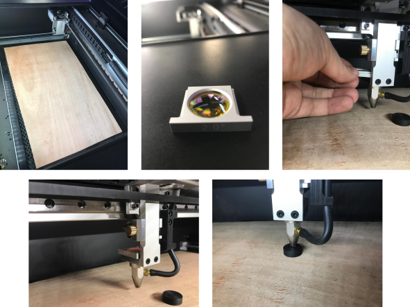
Characterising the Focus
Focusing the Muse laser cutter is quick and easy. It included a billet sized for the included 2-inch focal length lens.
- Place Billet: After inserting the material into the workbed, we placed the billet on top of the material. (Note that if your material isn’t flat, you may need to cut the material in stages, focusing each time to each new material level).
- Release Locking Mechanism: We released the locking mechanism on the focus head until the air assist nozzle rests on top of the billet.
- Retighten: Finally, we re-tighten the sliding head and removed the billet from the material.
Characterising the Power and Speed and Rate
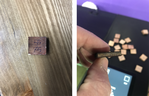
First, we start to determine the optimal cut parameters that not over-cutting or barely cutting by cut a several rectangles in different colors (red, black, orange, yellow, etc) for several materials.
We tested on:
- Plywood: 4.7mm
- Black Acrylic: 4.7mm
- Transparent Acrylic: 2.85mm
- CardBoard: 6.2mm
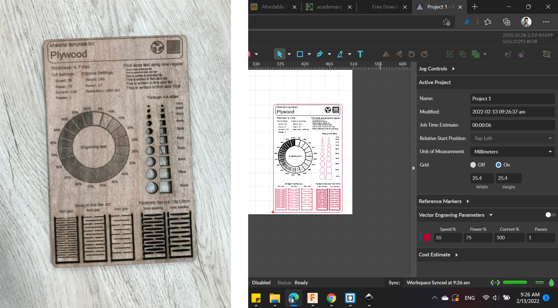
We started work with Plywood
Tags allow you to create separate vector layers and keep track of them with a unique color. Each color will match an object in the workscreen. So in order to reduce testing time, we made a lot of colored squares with different settings.
Also, you can set the order of operations by clicking on the “three dots” and then dragging the layer up or down. Objects are then processed from top to bottom.
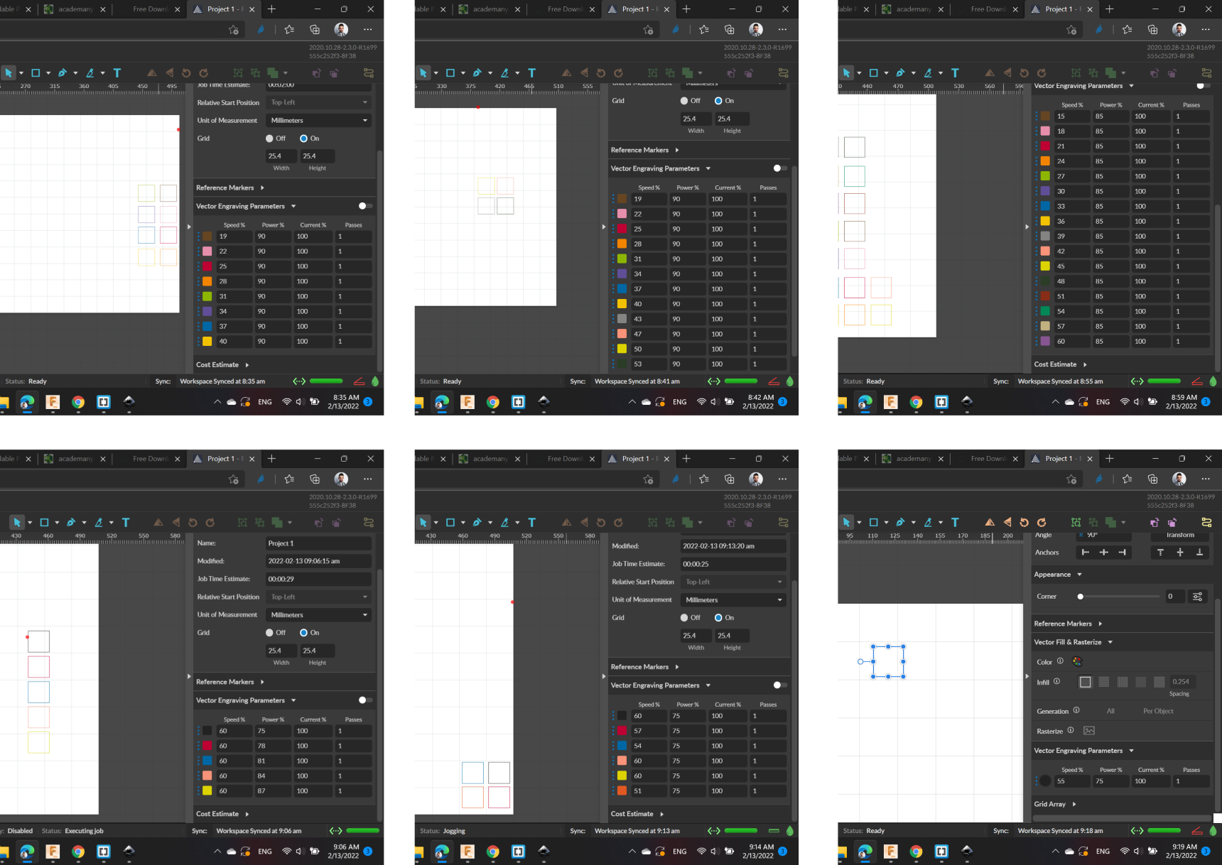
Many squares were cutted with different settings. And the optimal cut parameters was
Speed: 57 / Power: 75 / Current: 100 / Passes: 1
For Engrave, many tests we made too to ensure the optimal parameters, and we got the
Speed: 100 / Power: 27 / Resolution: 1000 dpi
In order to characterize the cutting/engraving power and speed for the laser cutting machine, we searched for a material test template that has rectangles, triangles engraving level and living hinges. And we Found this one (Laser Cut Materials Testing Template).
The results are shown in the following image:
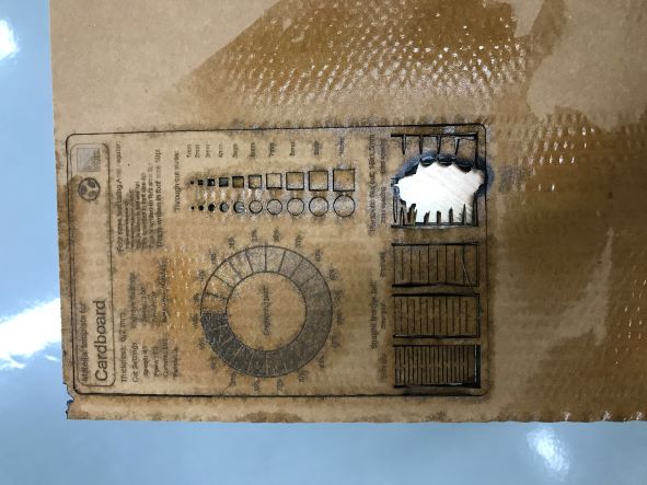
A very important tip: DO NOT LEAVE THE LASER MACHINE UNATTENDED DURING OPERATION.
The fire caught the cardboard.
It would not have been extinguished if we are not immediate intervention by stopping the machine, then we took out the burning piece and poured it from the water, so that it would be extinguished.
Everything was fine, the cut parameters were perfect, but suddenly and without warning we noticed a fire. So please be careful and stay close to it.
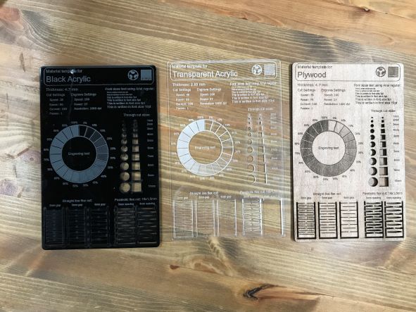
Finally, we made four Laser Cut Materials Testing Template for Plywood, Black & Transparent Acrylic, and Cardboard.
Characterising the Kerf, Joints Clearance, and Type
Here we come to the important part of the assignments.
Kerf is defined as the width of material that is removed by the cutting process. It was originally used to describe how much wood was removed by a saw, because the teeth on a saw are bent to the side, so that they remove more material than the width of the saw blade it self, preventing the blade from getting stuck in the wood.
First, we started with Black Acrylic.
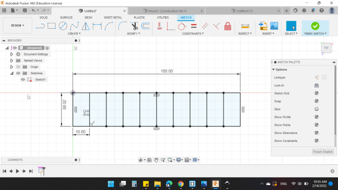
I sketched a rectangle with dimensions of 100mm x 20mm to check the best kerf in different settings using Fusion 360, then I divide it into 10 equal rectangles, as seen below.
We made the test using the same parameters that we have got for Black Acrylic 4.7 mm:
Speed: 25 / Power: 90 / Current: 100 / Passes: 1
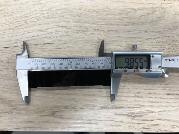
After cutting, we line up the ten rectangles side by side, and measure the total distance; We got the distance equal to 98.55mm.
Kerf's equation is:
So,
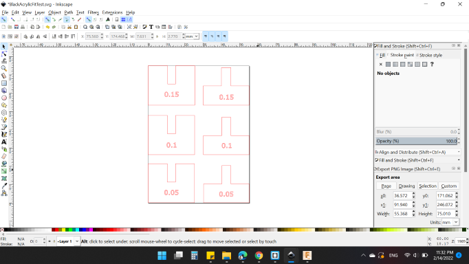
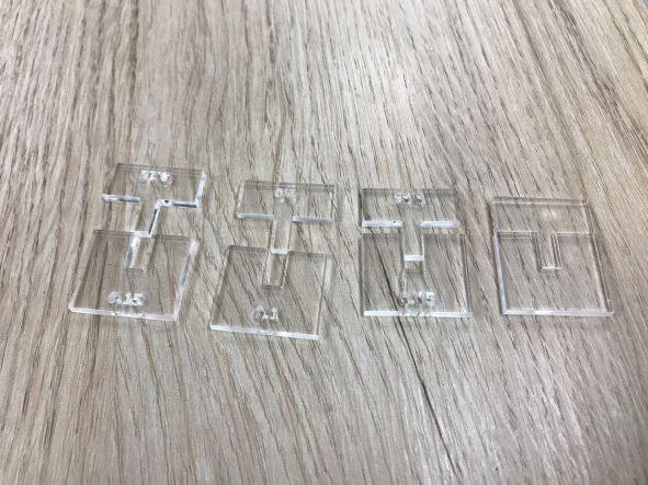
To avoid cutting a lot of rectangles and calculate the Kerf, we used Rule of Thumb for tolerances which is (0.05, 0.1, 0.15)mm.
It's quite simple, we added these tolerances for the first Kerf number we got, so we have many numbers to test.
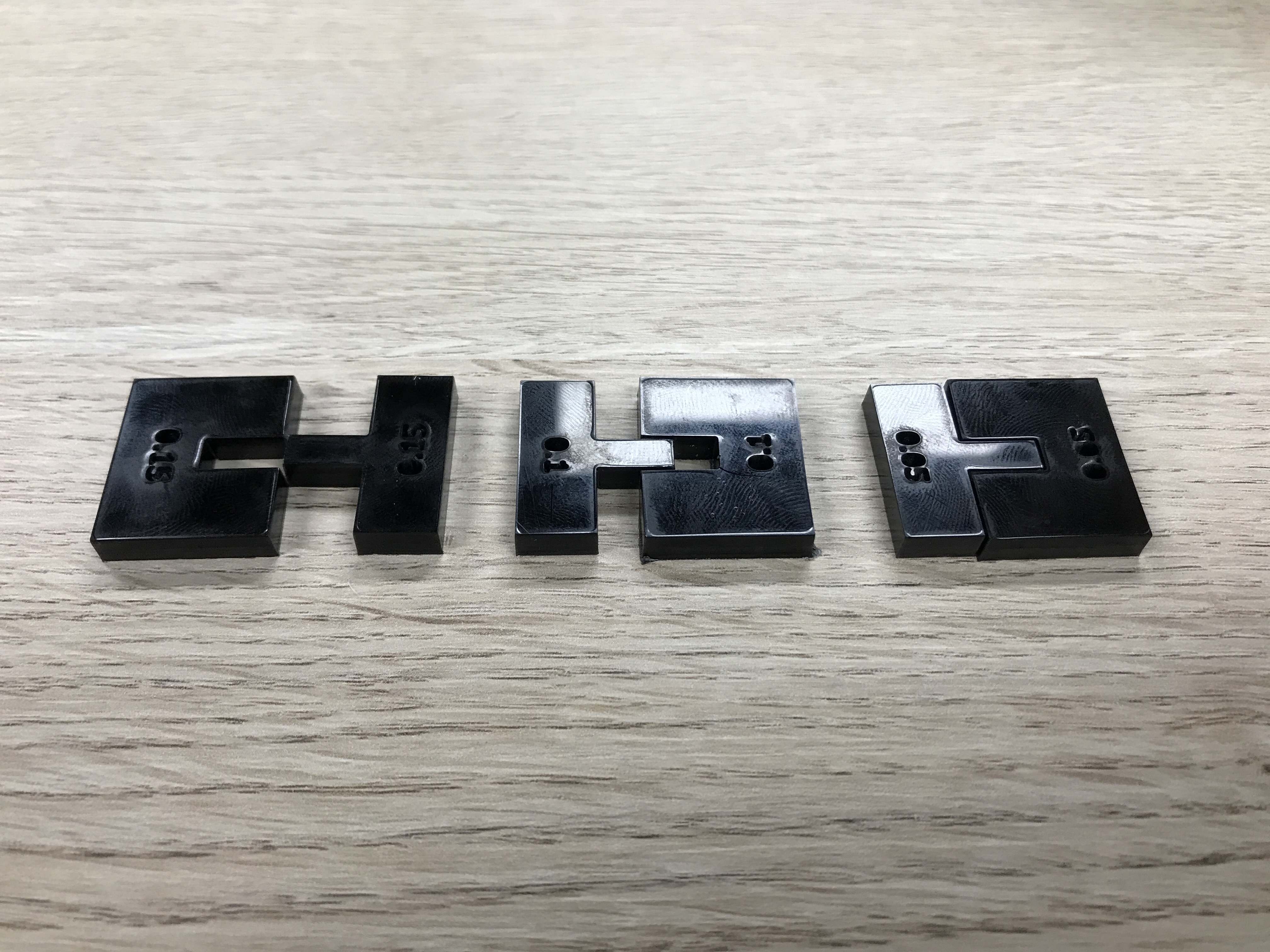
Then, we designed a suitable shapes for the test as shown below:
The results showed that Kerf + 0.05mm is good fit
For Transparent Acrylic, we made the same steps. Big rectangular with small 10 rectangles, and the distance equal to 98.13mm
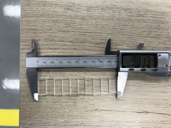
Calculating the Kerf and cut the simple shapes, we noticed that Kerf is enough and provide a good fit.
Individual Assignments
Parametric Construction Kit
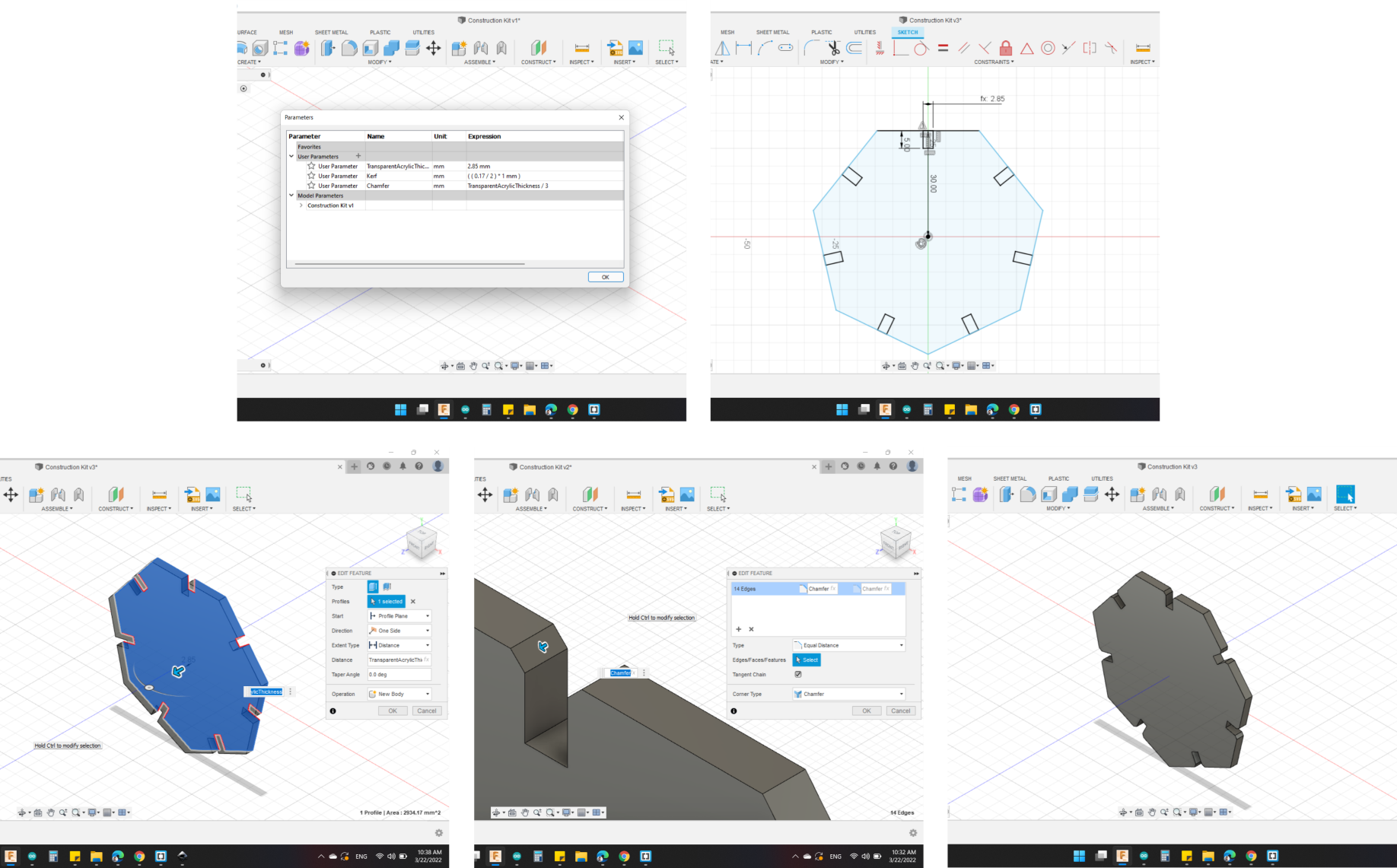
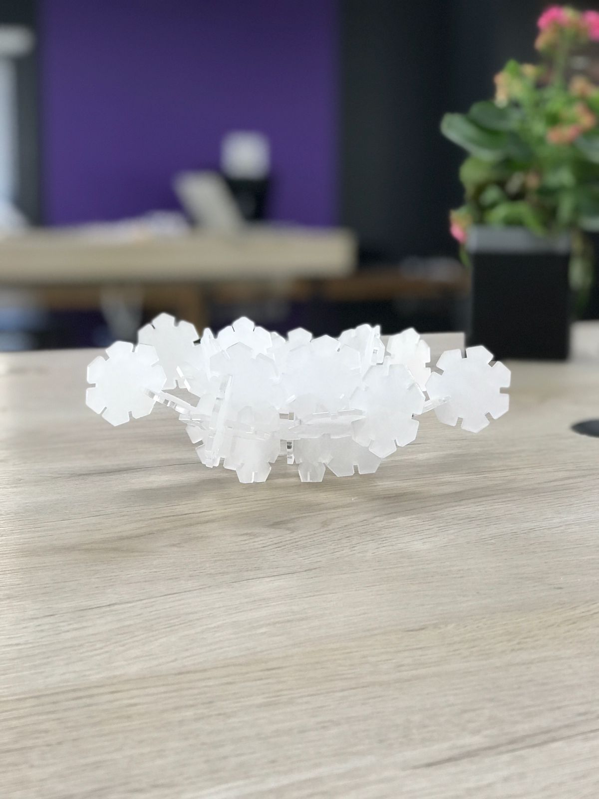
First assignment is to build a Parametric Construction Kit; I decided to design and fabrication a heptagon parts that can be assembled in multiple ways with Transparent Acrylic.
So, I built three parameters
- TransparentAcrylicThickness = 2.85mm
- Kerf = ((0.17/2)*1mm)
- Chamfer = TransparentAcrylicThickness / 3
Then, with Offset option, I made it by Kerf value.
For the best use of the transparent board, I lined up the pieces as close as possible to increase their numbers.
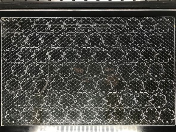
When I started connect the pieces together, I noticed that the model was not showing up properly because of its transparency.
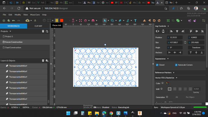
I didn't plan to cut the shapes in other colors, to not lose the previous pieces and waste time. So, a nice idea came to mind. I engraved all the pieces until it gives a beautiful white color.
Therefore, I drew a large rectangle that covered the entire work area, to accommodate all of the pieces needed (I didn't engrave all the pieces, just a small number to make sure of appearance).
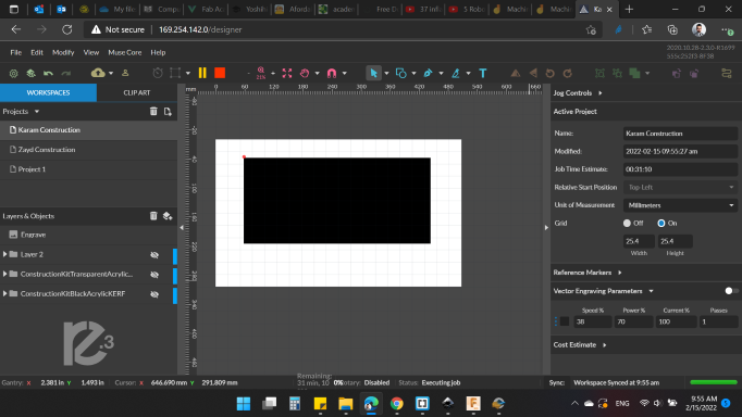
And here is the result!
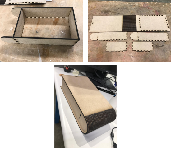
Living Hinge
A living hinge is a thin flexible hinge (flexure bearing) made from the same material as the two rigid pieces it connects. It is typically thinned or cut to allow the rigid pieces to bend along the line of the hinge.
I learned a new way of designing with Fusion 360 it's a Sheet Metel.
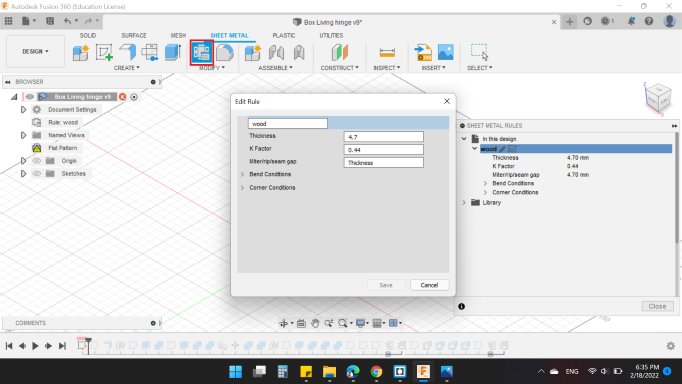
First of all, you need to set the rule from "Sheet Metal Rules" option in order to control the thickness, bend radius, reliefs, and other settings related to sheet metal design.
I created a new rule for wood with Thickness of 4.7 mm and K Factor of 0.44.
About K-Factor:
The K-Factor in sheet metal working is the ratio of the neutral axis to the material thickness. When metal is bent the top section is going to undergo compression and the bottom section will be stretched. The line where the transition from compression to stretching occurs is called the neutral axis. The location of the neutral axis varies and is based on the material’s physical properties and its thickness. The K-Factor is the ratio of the Neutral Axis’ Offset (t) and the Material Thickness (MT). Below the image shows how the top of the bend is compressed, and the bottom is stretched.
For more information you can visit SheetMetal.Me
In my case, I want to bend the wood using Living Hinge technique, so I kept the K-Factor as default.
After the rules are set, I choose the sketch option, and drawn on the front plane.
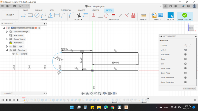
Then I clicked on Flange option to create a contour flange with 150mm distance.
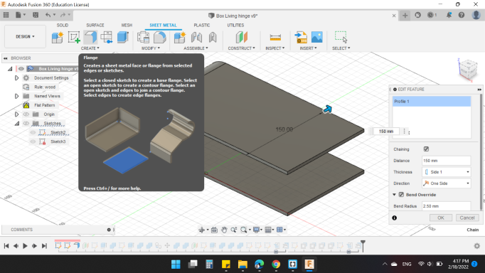
The rest of the steps are simple steps that do not fall within the scope of Sheet Metal space, you can see in the below video.
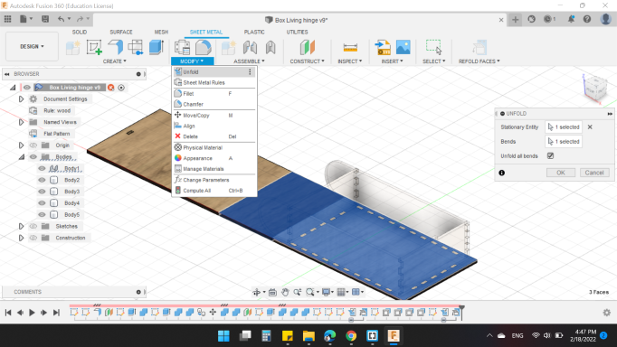
As we know, Sheet Metal manufacturing process doing by CNC Router, Laser Cutter, Water Jet. etc, which is in 2D cut. So, you need to unfold the surface in order to export the sketch or draw on it before export it.
By Unfold option you need to select the "Stationary Entity" and the "Bends" surface. In my design, the Stationary is the bottom face, and the Bends is the curved surface.
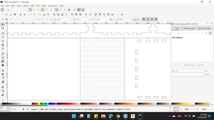
After I prepared the design for all sides, I wanted to draw the living hinge, but I heard that Inkscape has a feature to add living hinge.
In order to get the feature, you need to download the extension first.
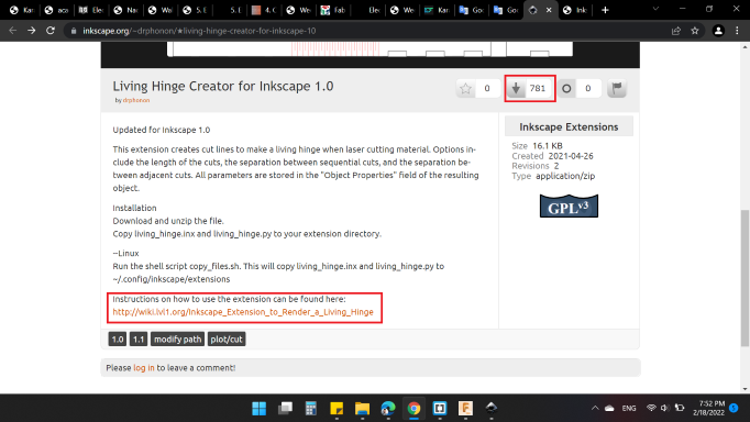
From the Living Hinge Creator for Inkscape 1.0.
You need to click on the arrow to download. And in order to know the instructions, click the link Inkscape Extension to Render a Living Hinge.
In my laptop, the extension was (Local Disk (C:) > Program Files > Inkscape > share > extensions)
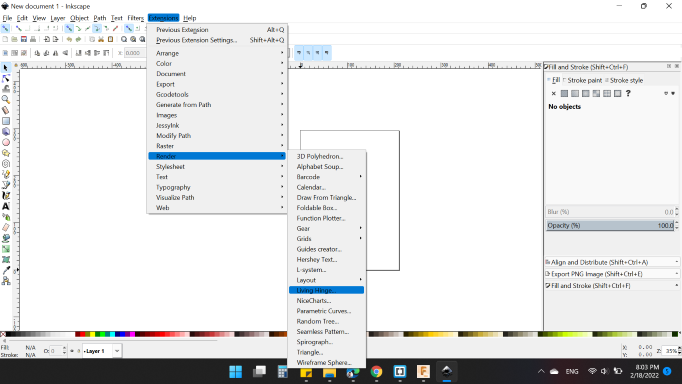
Then I opened Inkscape. You will find the feature from Extensions > Render > Living Hinge.
I chose the area (the rectangle) that I wanted to add the feature on. Then I wrote the parameters below:
- Cut Length (y): 30mm
- Gap Length (y): 7mm
- Separation Distance (x): 3mm
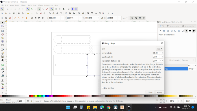
Here's the result:
Then, I used the kerf 0.2mm for my model to have a strong fit.
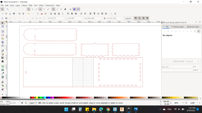
After cutting and rising dust, here's my model:
Laser Cut 3D Model
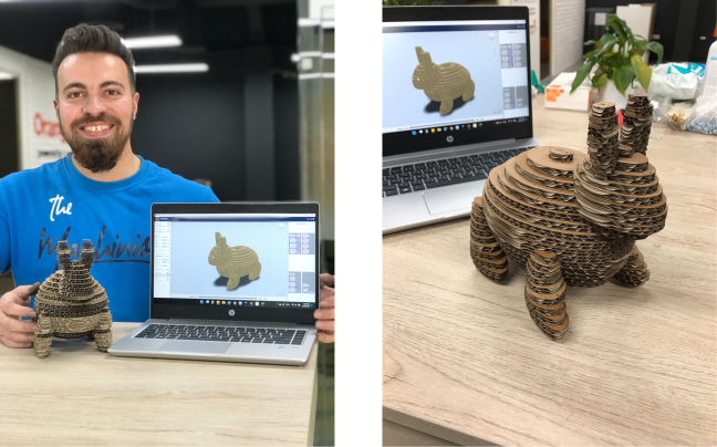
I wanted to do something extra and beautiful. I thought carefully and it came to my mind to design and manufacture a 3D model using a 2D laser machine!
I went to my friend Fusion 360, and learned a new tool Form Design!
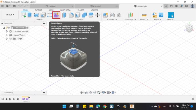
By using a QuadBall from Create list, I tried to design a rabbit model. So, quadball with 80mm looks good for me.
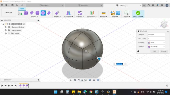
The idea of the form is the possibility of design without geometric measurements, that is, you can drag and lengthen points, lines, and faces as you wish.
This is what I did using the edit feature Edit Form.
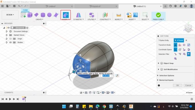
By adding some quadballs and modifying their shapes, and most important do not forget to be patient! I got the desired shape (Not exactly what I want, but close) 🤣
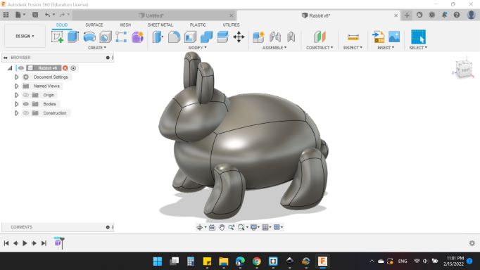
Last thing, I saved the design as .stl format.
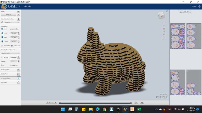
As I said before, I want to design a 3D model using a 2D laser machine. To do that, I need to slice it. So, again Fusion 360 and the whole family saved me. A nice software called "Slicer for Fusion 360" is the one.
 is a tool to turn your digital 3D models into appealing artefacts. It slices and converts 3D models into 2D patterns that you can cut out of any flat material. Slicer for Fusion 360 also creates 3D instructions you can interact with, to help build a model.
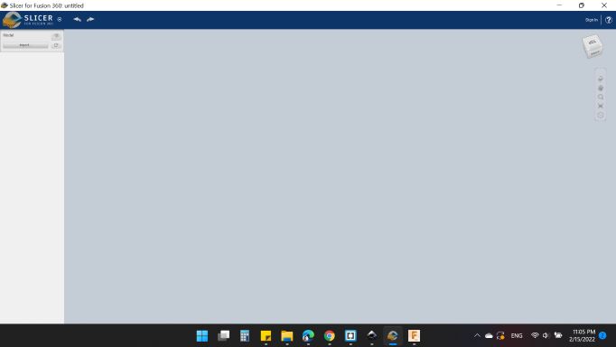
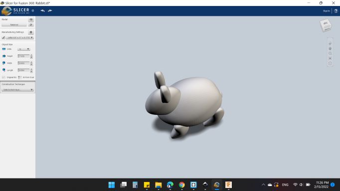
From Import, I opened my model.
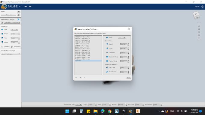
Notice that on the left side of the screen, there are the "Manufacturing Settings". I choose "unmanned _0" to write my board dimensions.
I decided to use a Cardboard with 6.2mm thickness. The size is based on the laser machine that I used, which is (500mm x 300mm).
On the "Object Size" I choose the Units "mm" and select "Orignal Size".
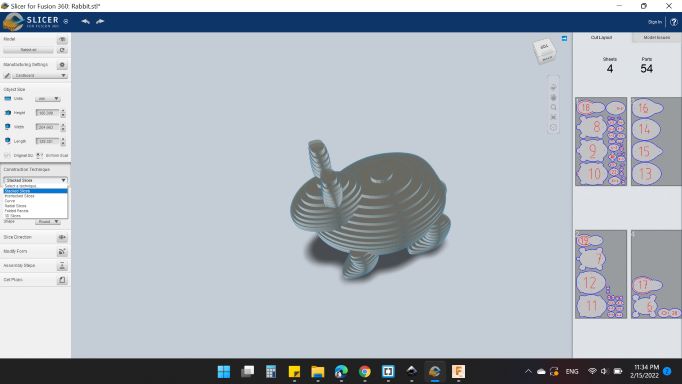
For the "Construction Technique" I choose "Stacked Slices". As you can see, there are 6 slicing modes that are available in the software. Each mode slices your 3D model in a different way.
Last but not least, For the "Assembly Steps" I choosed "Cardboard". This option enables you to see step by step how you will assemble the 2D parts that you will manufacturing in order to create a 3D model out of them.
Once you are done with slicing and you are sure about the final shape of your sliced 3D model, you can export the 2D plans. To do that, I selected the "Get Plans" option from the menu on the left side of the screen.
The available formats for the "File Type" are: EPS, PDF or DXF. I choose DXF formats. Then I selected the option "Export to My Computer" and downloaded the file.
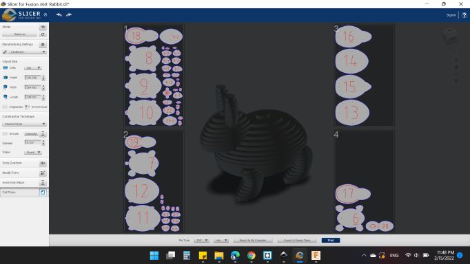
The model needs four sheets of cardboard.
After choosing the correct settings and arranging the pieces on the board. It's really good!
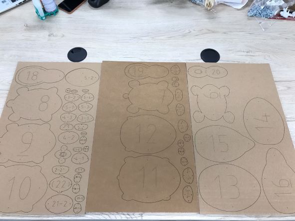
It's time to build the nice model.

Individual Assignment
Vinyl Cutter
A vinyl cutter is a type of computer-controlled machine. Like a printer controls a nozzle, the computer controls the movement of a sharp blade over the surface of the material. This blade is used to cut out shapes and letters from sheets of thin self-adhesive plastic (vinyl).
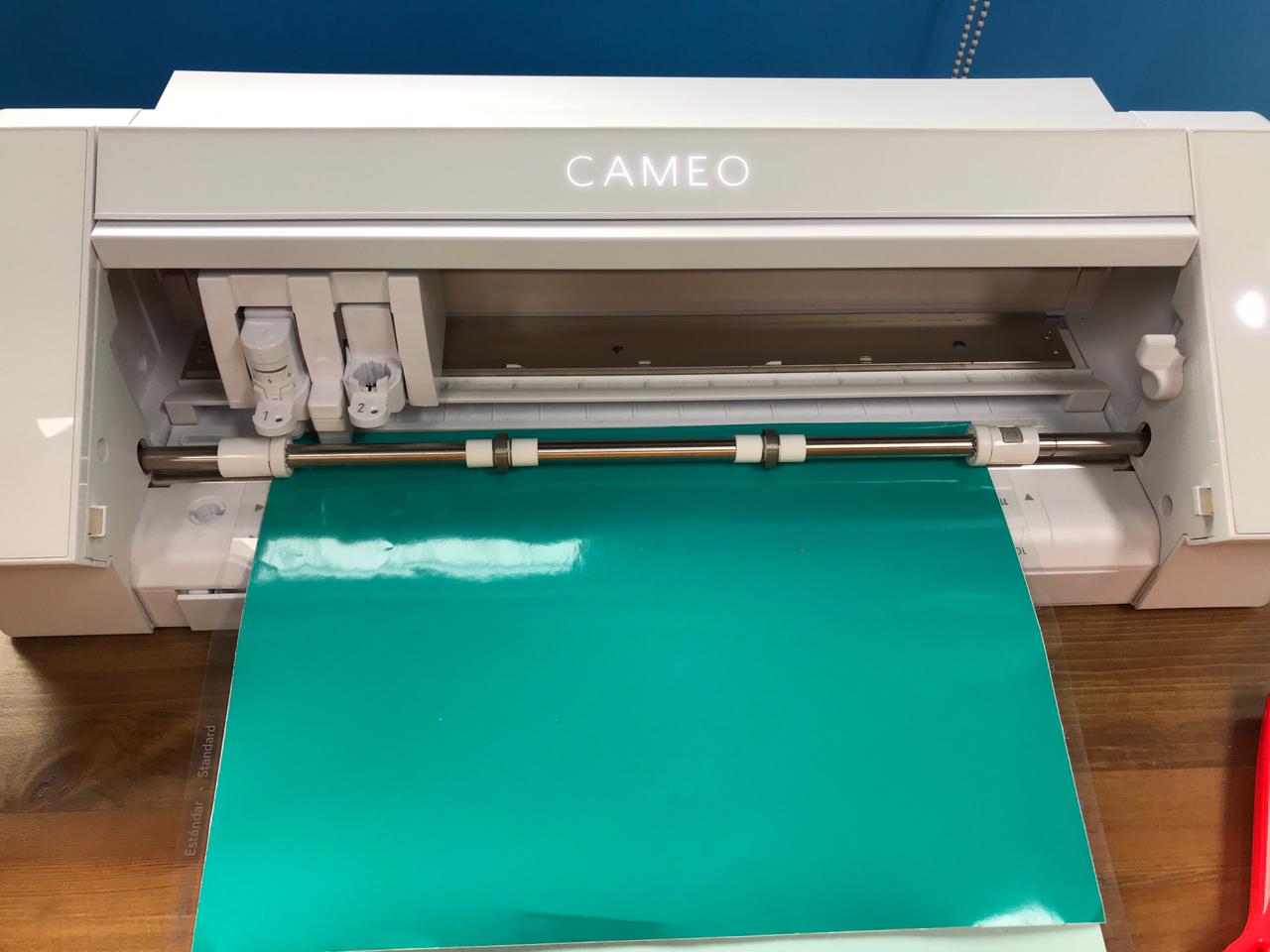
After cutting with a laser machine, and the dust from the effects of cutting, we needed a nice and beautiful machine to finish the assignment of this week, which is Silhouette Cameo 4 to perform the job.
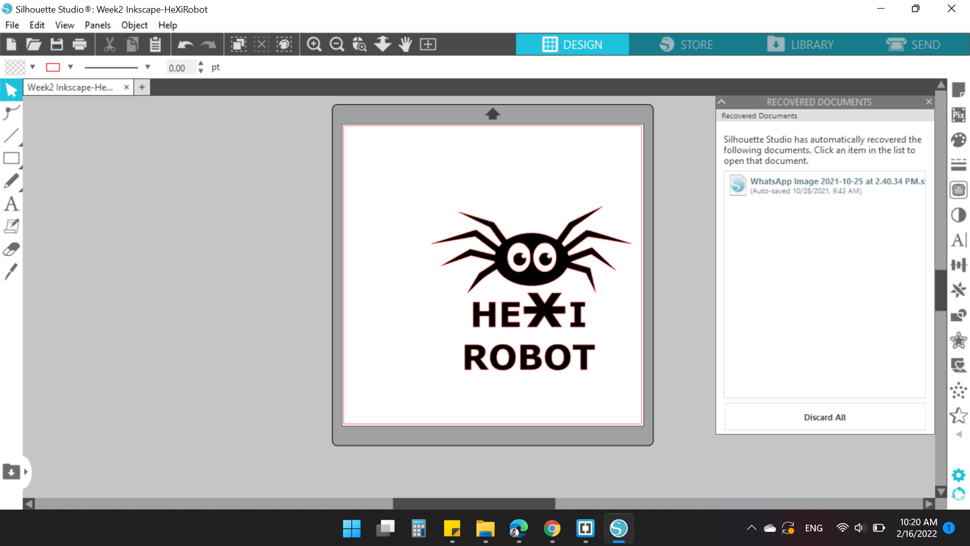
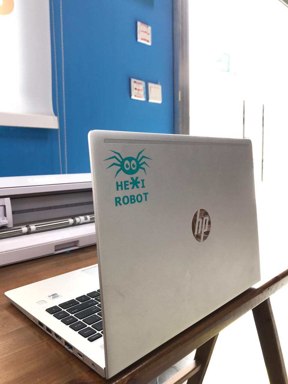
I wanted to make a HEXIRobot sticker that I designed last week.

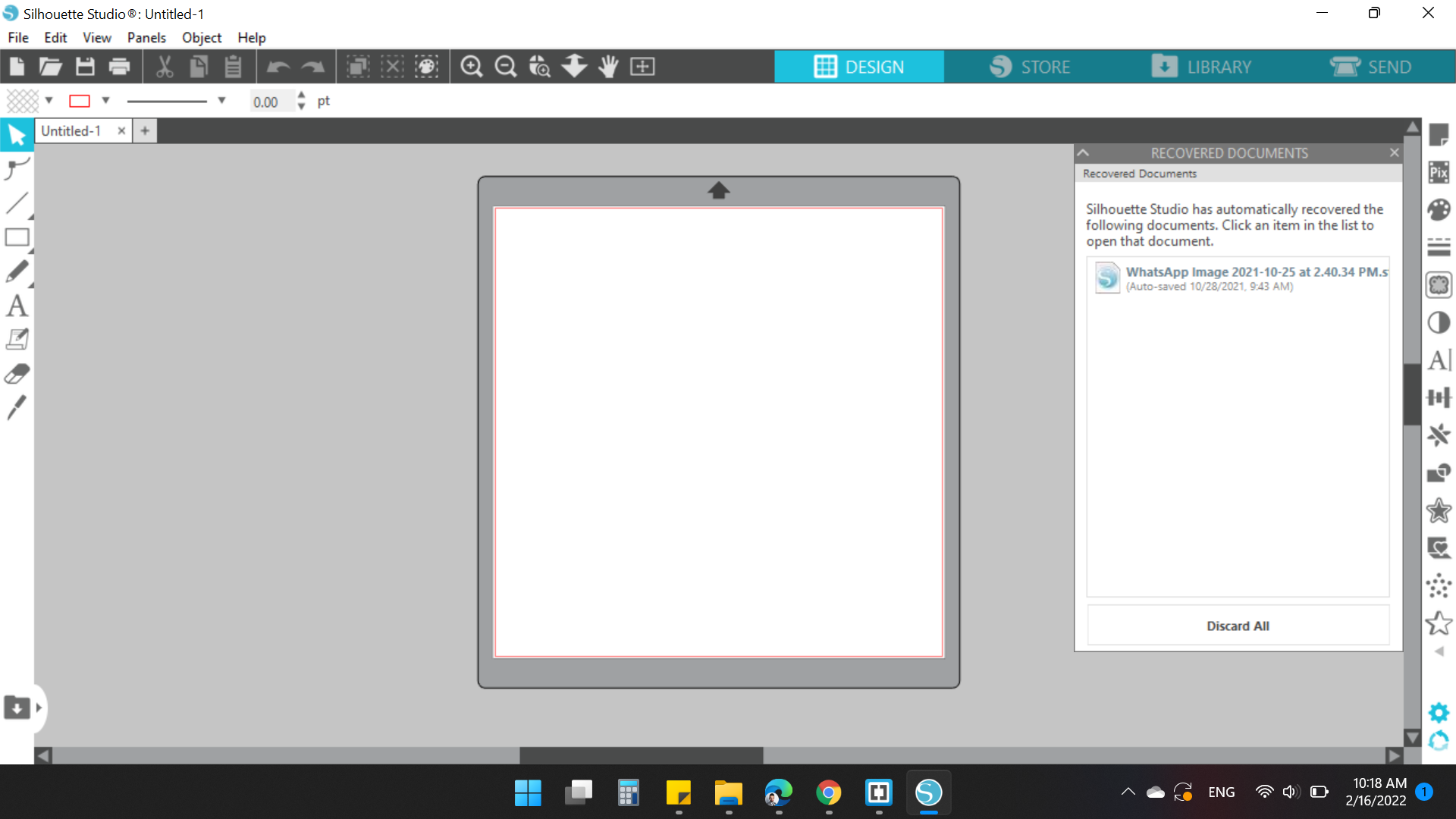
After saving the image as .png format, I opened the operation software, which is  . Silhouette Studio is a premium software that can meet all of your designing needs.
Before I work on my design, I must first make a test with it to determine the strength and depth of cutting with the tool, and to make sure of all calibres so that the cutting is appropriate and the machine works perfectly.
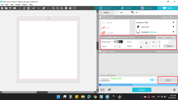
So, I clicked on SEND option at the right top of the software (Here you can send your design to the machine).
Also, you need to connect the printer to the laptop, either via a cable or via Bluetooth (and this is a great option as in a Muse laser machine).
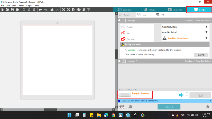
Before click the TEST option, you need to insert the vinyl sheet to the machine.
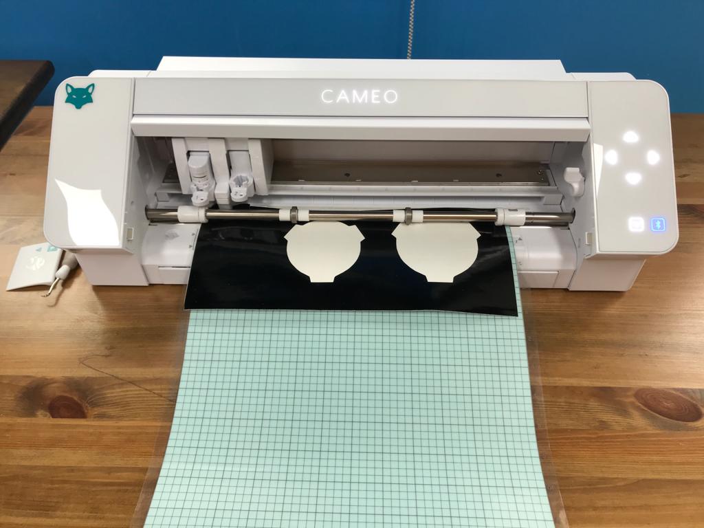
After the connection and inserting the sheet, I clicked on TEST option to test the cut parameters:
- Blade Depth = 1
- Passes = 1
- Force = 20
- Speed = 4
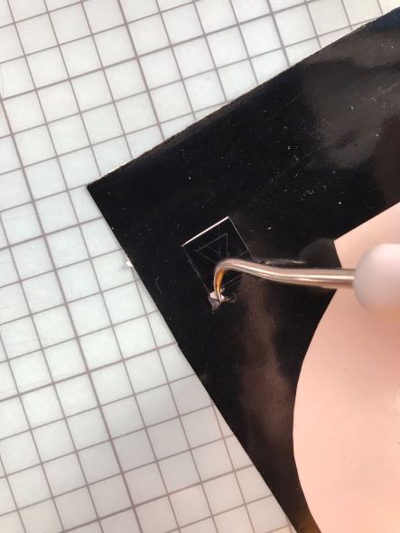
The result was not satisfactory, I could hardly get the cut piece out, I had to tear off the paper!
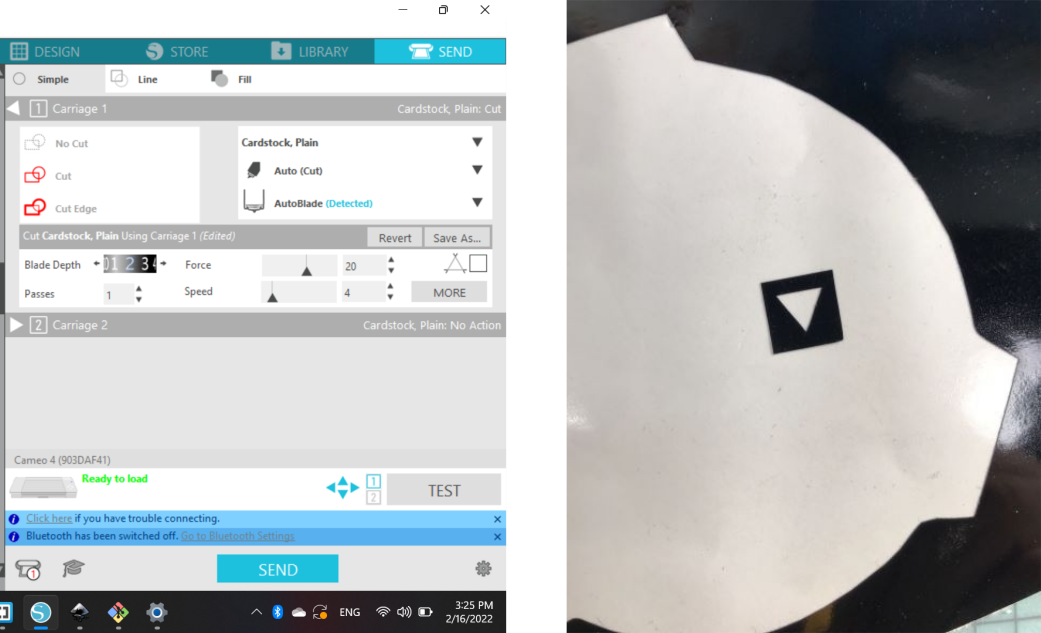
After several trials, I got a good result:
- Blade Depth = 2
- Passes = 1
- Force = 20
- Speed = 4
Now, it's time for my design.
I inserted the image into the workspace, and changed the image dimensions to (57.2mm x 70mm). Here in this cool software, you can edit your model as you want!
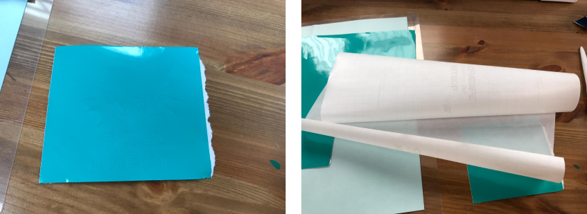
With the last cut parameters settings, I cutted my design with Turquoise color sheet, the color looks so nice!
After you're done, you can remove the cut-out design, and stick it on the surface you want. But, but if there are any spaces or intricate details it will be very difficult. So, you need a transfare tape.
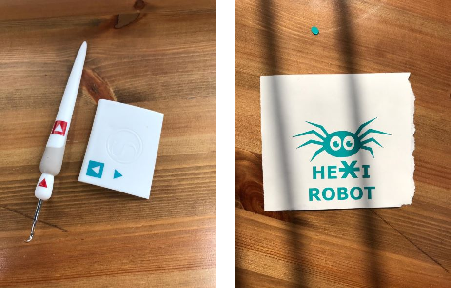
Hook Weeding Tool and Vinyl Scraper are your friend at this moment!
Here is the result after removing the background:
Here's the installation steps, hope you have fun!
You can download my files here:
- Week3: LS_PlywoodEngrave
- Week3: LS_BlackAcrylicEngrave
- Week3: LS_TransparentAcrylicEngrave
- Week3: LS_CardboardEngrave
- Week3: LS_ALLCut
- Week3: LS_ConstructionKit.f3d
- Week3: LS_ConstructionKit.svg
- Week3: LS_LivingHingeBox.f3d
- Week3: LS_LivingHingeBoxWithOffset.svg
- Week3: LS_LivingHingeBoxWithoutOffset.svg
- Week3: LS_Rabbit.f3d
- Week3: LS_Rabbit.stl
- Week3: LS_Rabbit.3dmk
- Week3: LS_Rabbit.dxf
- Week3: LS_Rabbit.svg
- Week3: LS_Rabbit.pdf