CAD (Computer Aided Design) is the use of computer programs to create two or three dimensional (2D or 3D) graphical representations of physical objects. CAD software may be specialized for specific applications.
CAD is widely used for computer animation and special effects in movies, advertising, and other applications where the graphic design itself is the finished product. CAD is also used to design physical products in a wide range of industries, where the software performs calculations for determining an optimum shape and size for a variety of product and industrial design applications.
I really love mechanisms and how mechanical systems work, so I decided to design a small part of my final project that contains movement points and joints, and to apply rendering, animation, and simulation.
Learning:
- Fusion 360
- Design
- Render
- Animation
- SolidWorks
- Design
-
Inkscape
- Design

Is a cloud-based CAD/CAM tool for collaborative product development from Autodesk.
Fusion 360 combines organic shapes modelling, mechanical design and manufacturing in one comprehensive package. It is functionally similar to other 3D software like Solidworks, Onshape, Rhino. etc.
Design
First of all, I have to say that, the interface is very beautiful and is easy to use. That's why I like it.
Last week I drew two robot shapes that I would like to be one of them my final project. After researching and studying the two designs, I decided to work on Hexapod Robot.
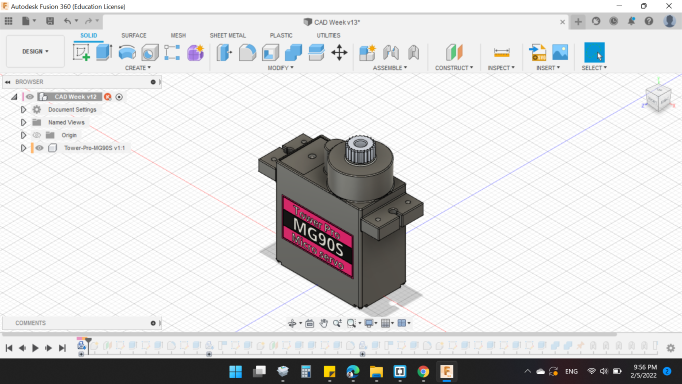
Each leg of the Hexapod Robot has 3 DOF, so 3 motor (servo motor probably). Instead of drawing the motor, I looked for a 3D model for it, to use in my design.
On  , I found what I was looking for, a MG90 Servo Motor.
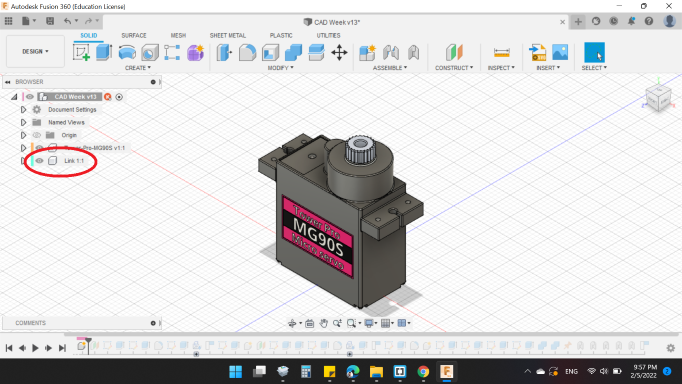
Always when I design a mechanical parts, I separated the parts in to components, in order for each one to contain the sketches and bodies individually, and so that I can animate the final shape.
First, I added a new component and named it "Link 1".
Then I created an "Offset Plane" in order to sketch on it, and add 10mm offset from XZ origine plane.
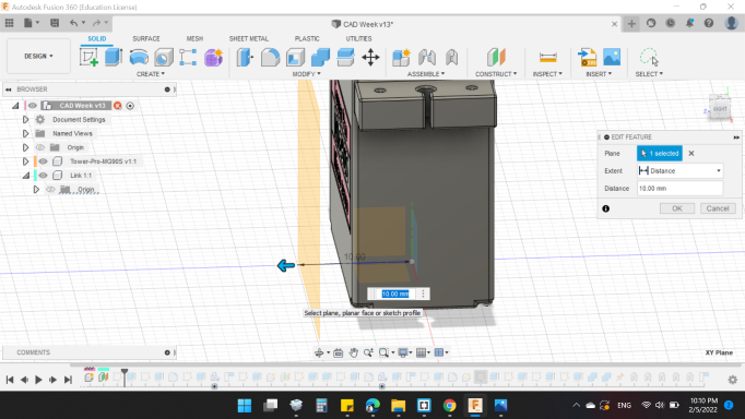
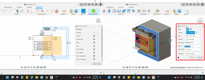
Then I drew rectangular shapes on the surface in order to make a piece connected to the motor. After that, I used Extrude command to add a third dimension to the sketch by 20mm.
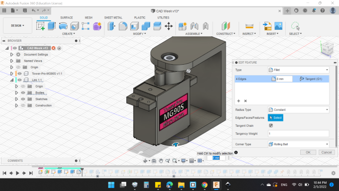
In order to reduce the stress concentration on the edges, and for appearance, I added "Fillet" by 8mm.
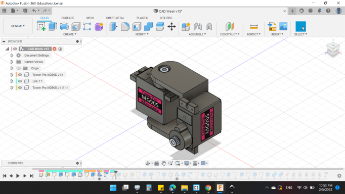
After that, I added the second servo motor next to Link 1.
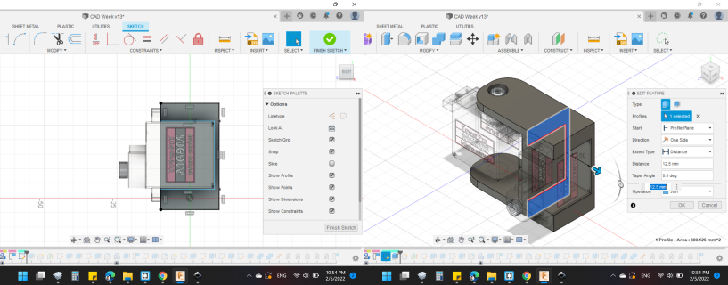
As I said right now, the second motor is next to the first link, so to install it, I sketched another rectangular shapes on the right side of Link 1. Then, extruded by 12.5mm.
Now it's time to make the second link. The way the Link 2 works is very similar to the Link 1.
Sketch a rectangular shapes, Extrude these shapes, Draw rectangular shapes, then Link 2 is born.
I realized later that I did not mention the red circles below. These circuits serve to connect the Links and the motors gear.
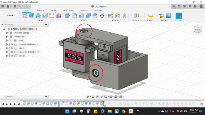
Link 2 is to connect the second and third motors, So I added a sketch to it and extruded it out like the rest, to become like a letter "H" (Also, by adding the circuit that I talked about to the third motor, and circular edges by fillets. The shape is about to complete).
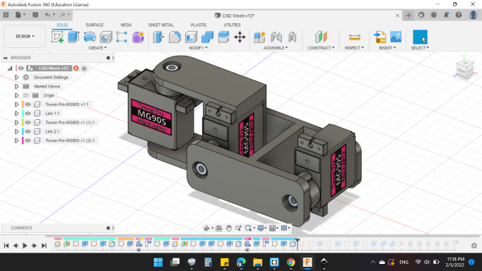
The connection of the third motor is to the last piece of the leg which is "Link 3".
I decided to sketch it in a triangular shape.
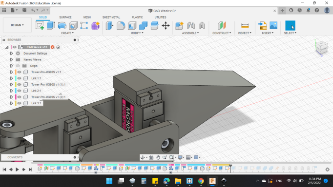
I emptied the triangle from the inside to reduce weight when fabricated. And here is the final look!
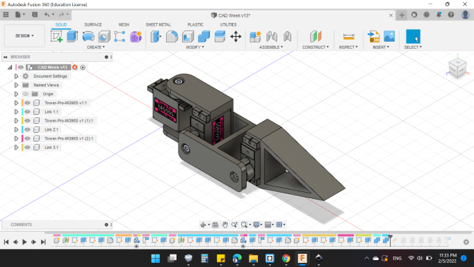
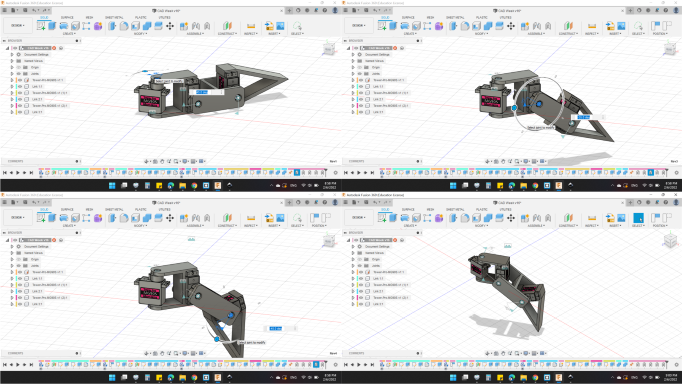
The fun part starts here. I'll move the leg!
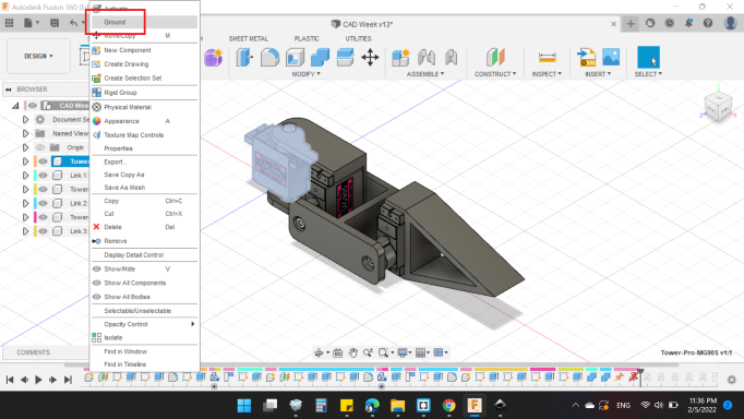
In order to activate the motion, joints must be added. First of all you need to ground one components to move the rest of the components accordingly. Right click on the desired component, and press ground. I grounded the first motor, because the movement of the leg depends on it.
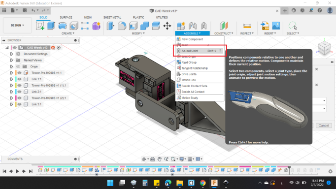
From "Assemble" press "As-built Joint"
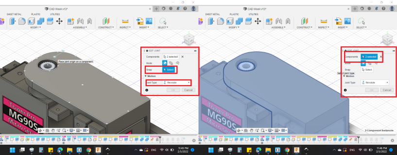
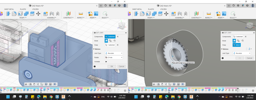
From the box that appeared, first you have to choose the two components, in my case, the first motor + Link 1.
Then the "Joint Type" from "Motion". I chose "Revolute", and "snapped" the rotation point to the center of the motor gear.
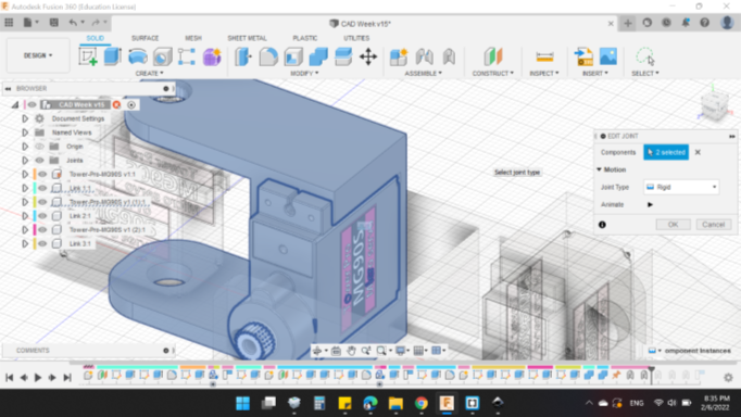
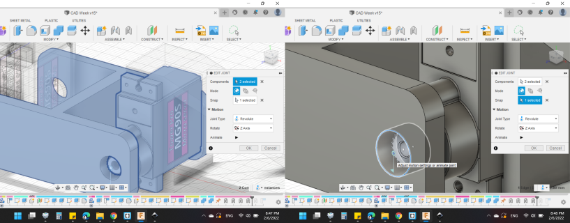
Next, I made another joint between Link 1 and the second motor. The "Joint Type" from "Motion" I chose "Rigid" to prevent the movement between them.
Next joint I made was for Link 2 and the second motor, to enable rotation. I chose "Revolute" from "Joint Type", and "snapped" the rotation point to the center of the motor gear.
Then another joint I made for Link 2 and the third motor to enable rotation too. I chose "Revolute" from "Joint Type", and "snapped" the rotation point to the center of the motor gear.
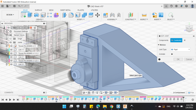
The last joint was between Link 3 and the third motor. The "Joint Type" from "Motion" I chose "Rigid" to prevent the movement between them.
Next step to be close to the fun part is here!
All you have to do is double press the rotation icons for the joints to enable the angle.
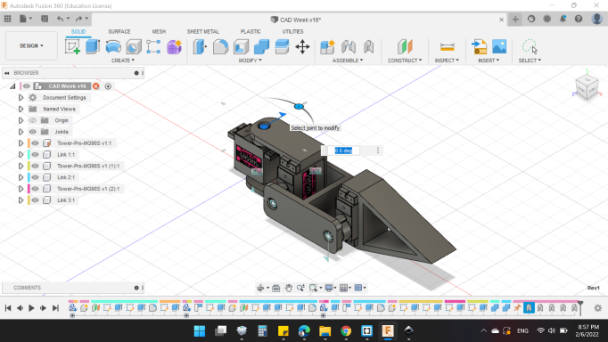
I changed all angles of the joints to get the shape of the leg. Really it looks good!
Here's my design in 3D view, you can rotate it and see it close.
In order to see the mechanical motion more clearly, and to know the angles for each motor, I made a Motion Study.
In Fusion 360, joints assemble components together to simulate the mechanical motion of an assembly. Different joints are used to drive the motion study. These joints are driven through time by either a distance or angle.
Briefly about the design;
- The first motor is attached to the body of the robot, and its goal is to move the whole leg forward and backward. Thus, moving the robot forward and backward.
- The second motor connects the first link with the second link, and its goal is to move the leg up and down.
- The third motor connects the second and third link, and the goal of it is to move the rest of the leg up and down.
To be able to record videos, I used  , easy to use and good for quick videos.
And the next video is to explain more:
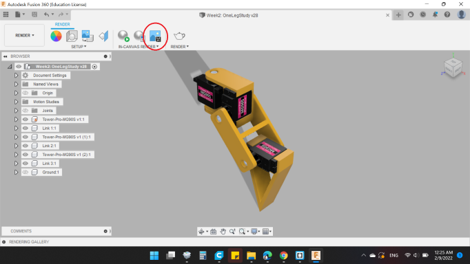
Render
3D rendering is basically the process of creating two-dimensional images (e.g. for a computer screen) from a 3D model. The images are generated based on sets of data dictating what color, texture, and material a certain object in the image has.
I didn't make changes in colors or lighting, I just got the picture from [Capture Image].
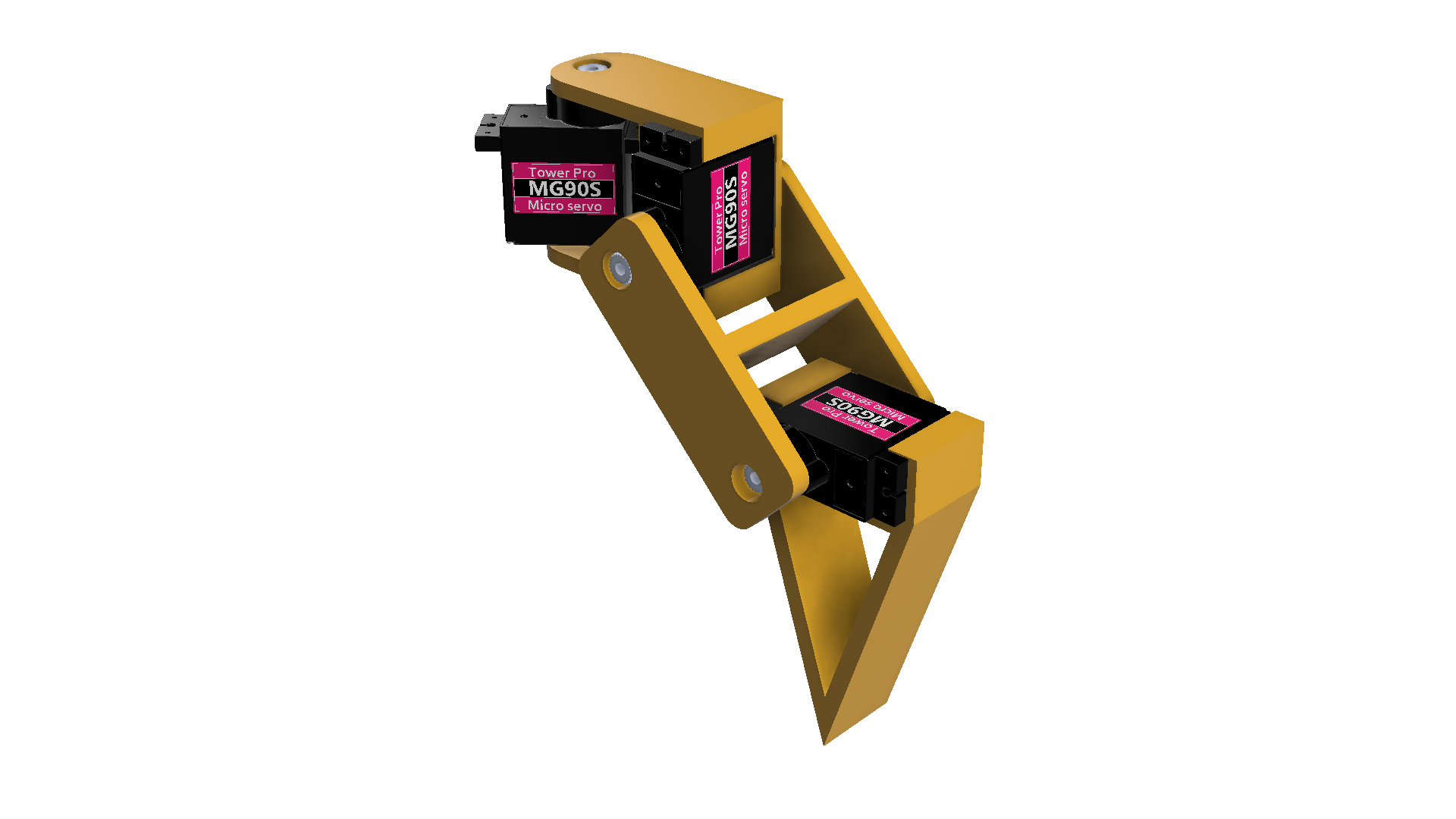
I resized the image to the appropriate size, which is [1920 x 1080 (16:9)] and enabled [Transparent Background] and disabled [Enable-Anti aliasing].
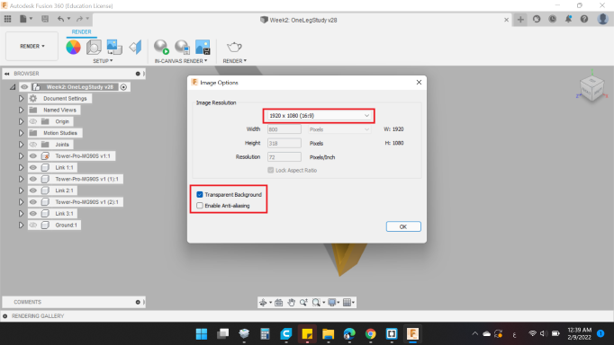
Here's the design picture.
Animation
As I said before, Fusion 360 is a powerful CAD software, it has many features that you usually find in separate programs not in one software.
Awesome thing I wanted to try is "Animation" in the workspace. The Animations workspace in Fusion 360 gives a dedicated toolset and environment specifically for generating exploded views and animations.

Is a powerful solid modeling Computer-Aided Design (CAD) and Computer-Aided Engineering (CAE) used to develop mechatronics systems from beginning to end.
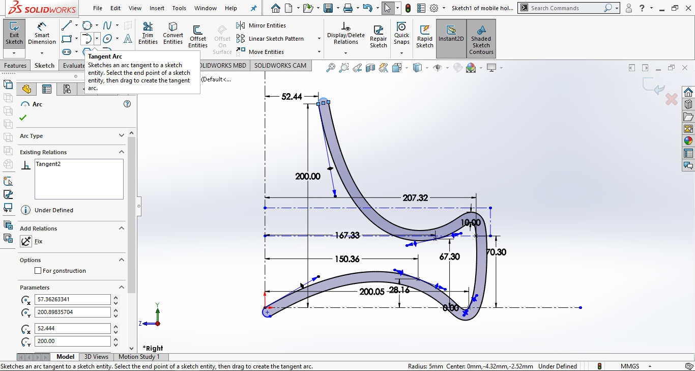
I want to make a holder for my mobile, I started with sketch at the right plane.
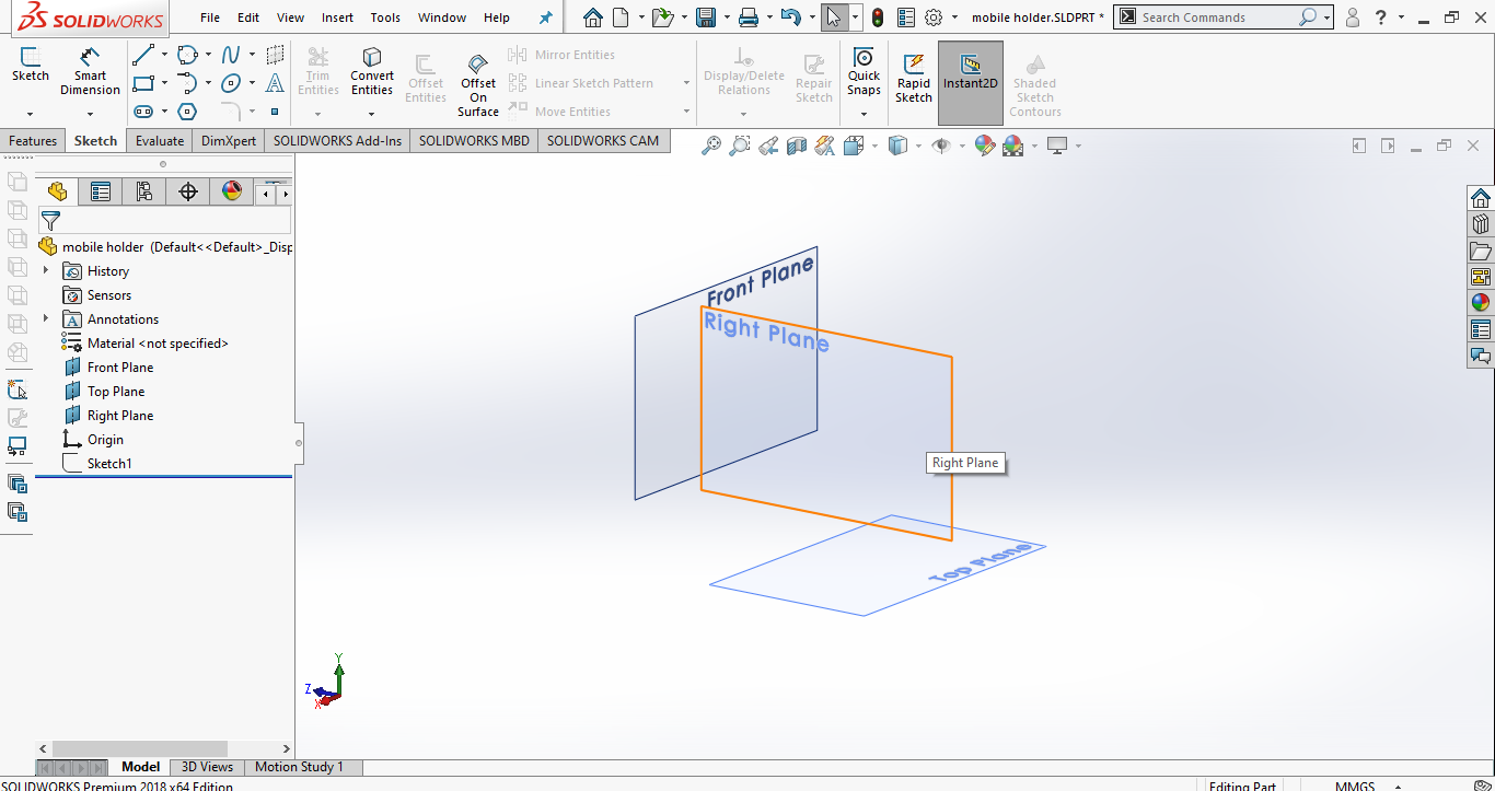
I sketched a Spline like the picture below, the curved shape represents the Mobile Stand.
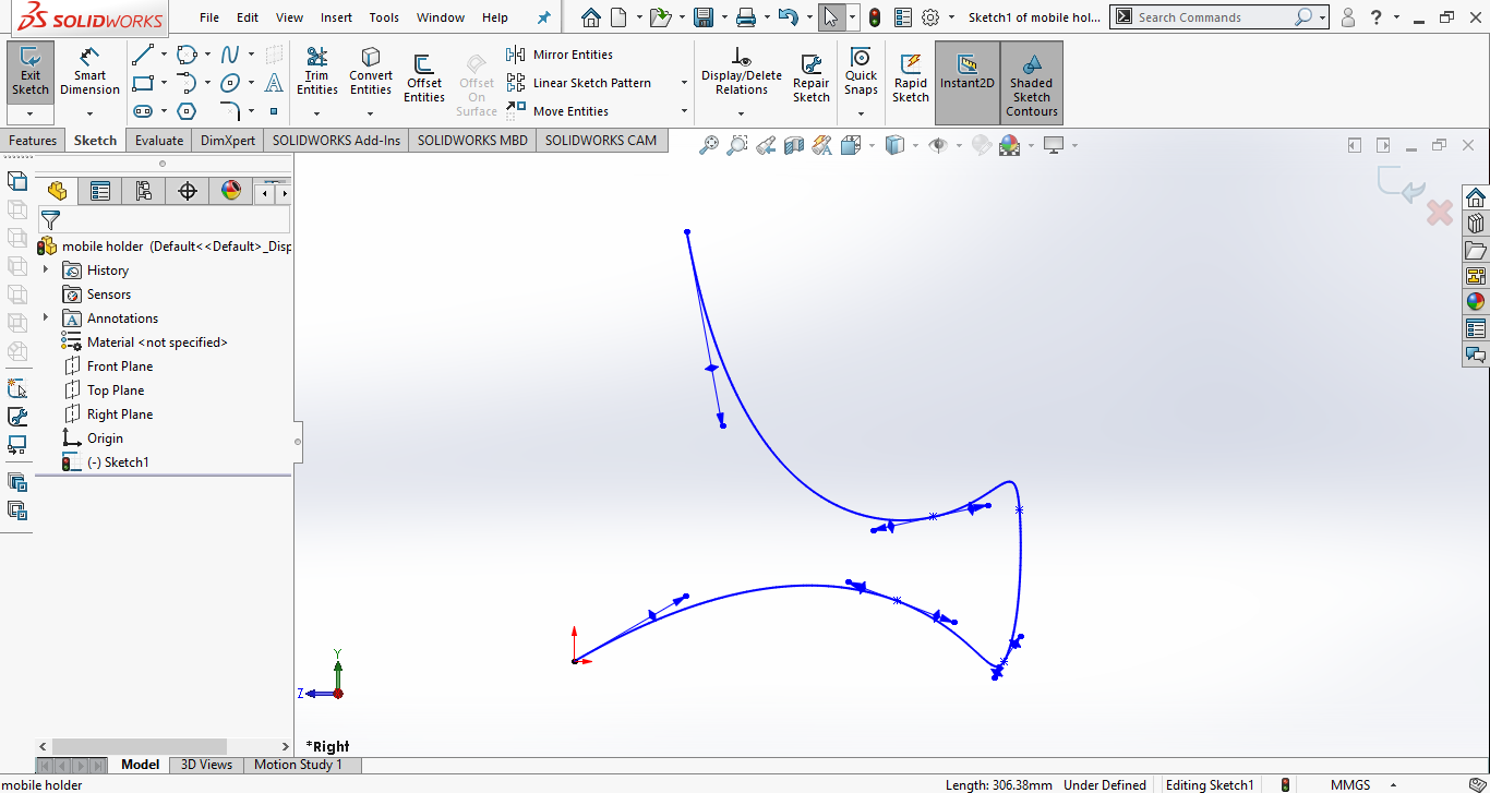
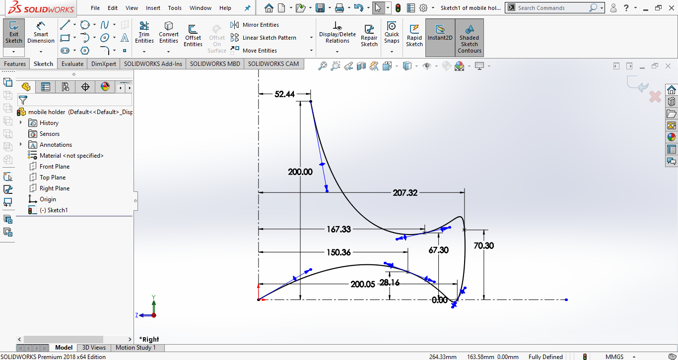
Like the Fusion 360, when the color is blue, it's means not fully defined, so I used Smart Dimension to add the dimensions, to be defined in black color as seen below.
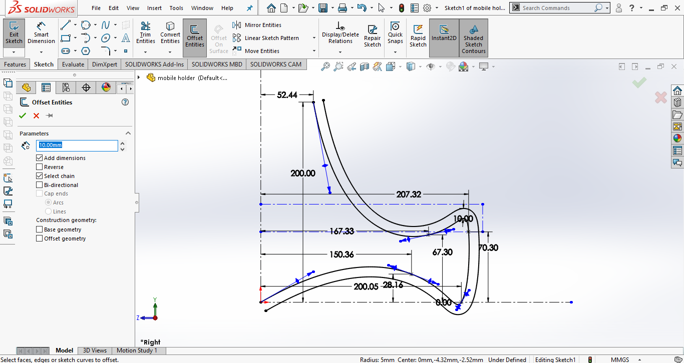
Then clicked on Offset Entities to have a thickness 10mm.
Then I used Tangent Arc on the start and the end of the shape to have a closed body.
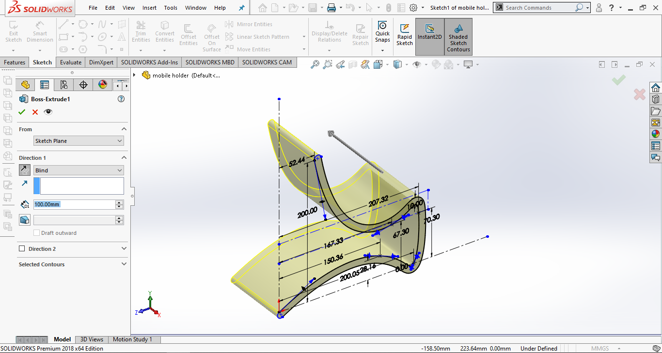
After the sketch is done, I clicked on Extruded to have a 3D body.
When the mobile is on the stand, a slot must be made in the stand to be able to extend the charger wire to charge the device. So, to do that, I built a Mid Plane to be able draw a sketch.
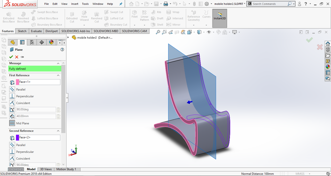
Then I drew a closed area to extend the charger wire.
After that, I chose Extruded Cut to empty the closed area by the two directions.
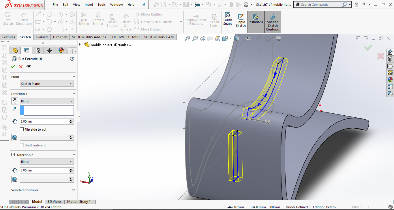
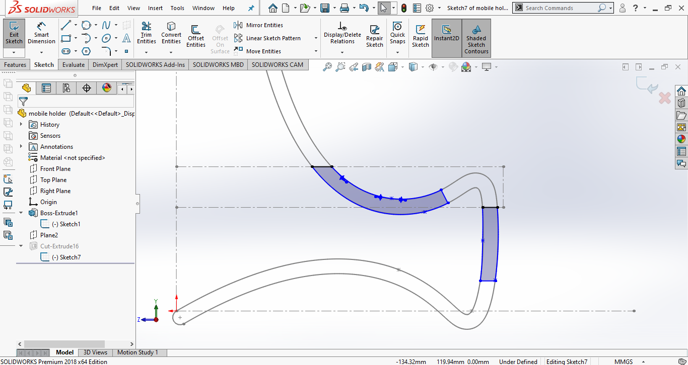
Then I clicked on the Fillet to have a circular edges.
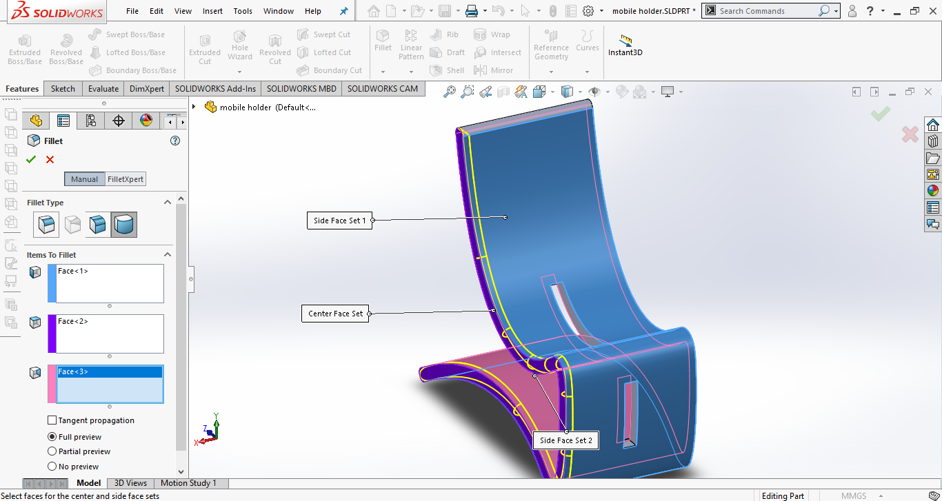
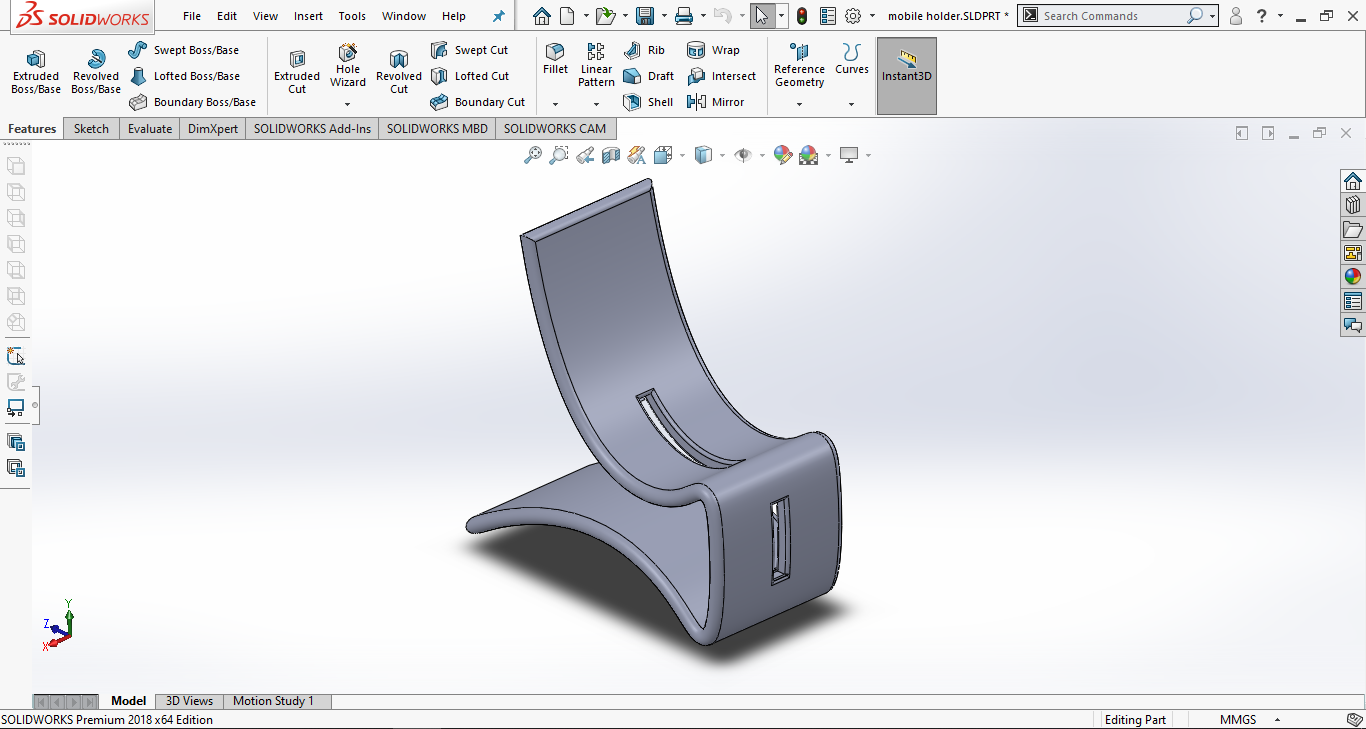
And the final design is done.

Is a free and open-source vector graphics editor used to create vector images, primarily in Scalable Vector Graphics format. Other formats can be imported and exported.
I decided to use it to make a logo for the final project; And by chance, as I thought about the logo, a name for the project came to my mind. I'll call my final project "HEXI ROBOT"
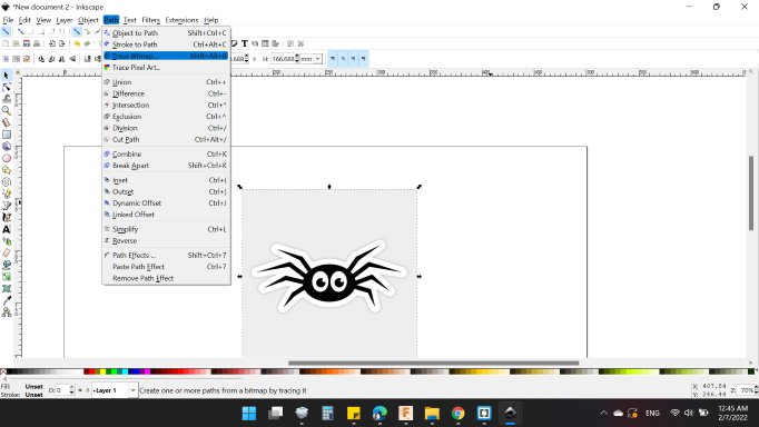
So, first I searched on sticker about spider with 6 legs to be similar to my project, found a nice one, and inserted it into the workspace.
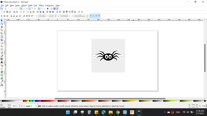
The image is not clear and need to remove the gray background, so it need to be converted from raster graphic to vector graphic to control the points and remove the unnecessary.
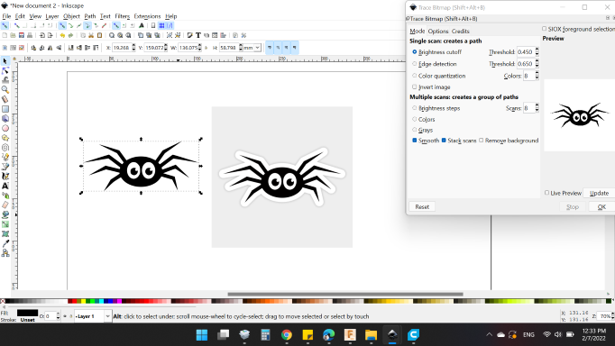
First, I selected the image and chose "Trace Bitmap".
Thus, I obtained the desired image.
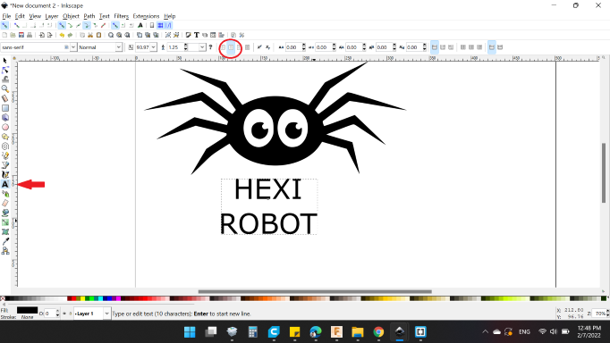
Next, I wanted to write the project name "HEXI ROBOT", So from "text" icon I written HEXI ROBOT and aligned the text in center position.
I thought a little, I also wanted to add an expression symbolizing the shape of the project in the project name.
The letter X has four sides (legs), I decided to add a horizontal line to make the shape with 6 sides (legs). And made the letter bigger.
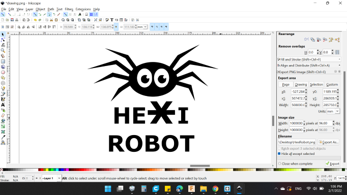
Here's the final design:

You can download my files here: