3D Printing is an additive technology used to manufacture parts. It is ‘additive’ in that it doesn’t require a block of material or a mold to manufacture physical objects, it simply stacks and fuses layers of material. It’s typically fast, with low fixed setup costs, and can create more complex geometries than ‘traditional’ technologies, with an ever-expanding list of materials. It is used extensively in the engineering industry, particularly for prototyping and creating lightweight geometries.
There are different technologies for 3D Printing but they all follow the same principle. Here in Techworks, We have many types of 3D printer technologies, which are:
- FDM: Fused Deposition Modeling.
- SLA: Stereolithography.
- SLS: Selective Laser Sintering.
- Delta WASP
Learning:
- Group Assignment
- Design Rules
- FDM / Original Prusa i3 MK3/S
- FDM / Ultimaker S5
- SLA / Form 3B+
- Delta WASP 3MT INDUSTRIAL 4.0
- Individual Assignment
-
3D Printing
-
FDM / Original Prusa i3 MK3/S
-
FDM / Ultimaker S5
-
SLA / Form 3B+
- 3D Scanning / Sense
-
3D Printing
Group Assignments
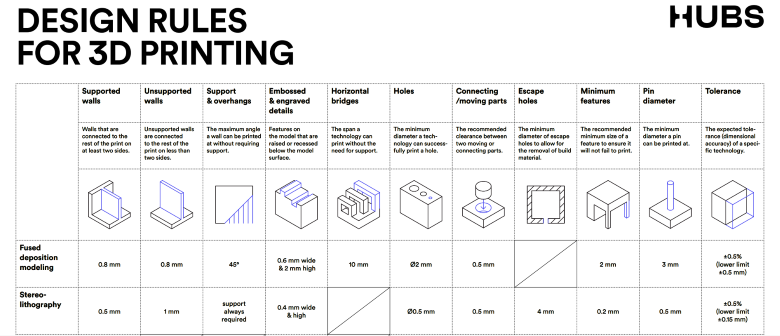
Design Rules

First of all, I recommend checking out the 3D Hubs. It is a site rich in information and important references for CNC and 3D printing, etc.
FDM / Original Prusa i3 MK3/S

Our first printer is Original Prusa i3 MK3/S.
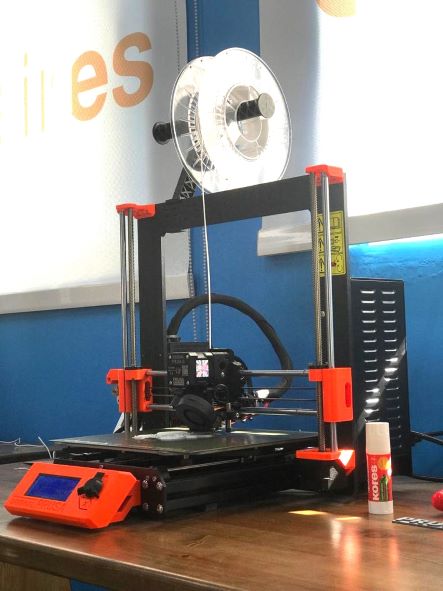
We did a All In One 3D Printer test to measured the settings.
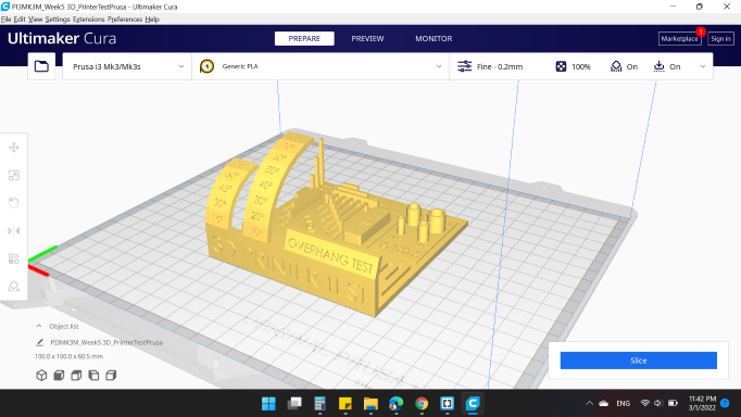
All settings have been made as defaults:
- Quality
- Layer Height: 0.15 mm. (The height of each layer in mm)
- Walls
- Wall Thickness: 0.8 mm. (The thickness of the walls in the horizontal direction)
- Infill
- Infill Density: 20 %. (Adjusts the density of infill of the print)
- Infill Pattren: Grid. (The pattern of the infill material of the print)
- Travel
- Enable Retraction: "YES". (Retract the filament when the nozzle is moving over a non-printer area)
- Z Hop When Retracted: "NO". (The build plate is lowered to create clearance between the nozzle and the print)
- Support
- Generate Support: "NO". (Generate structures to support parts of the model which have overhangs)
- Build Plate Adhesion
- Build Plate Adhesion Type: Skirt. (Different options that help to improve both priming your extrusion and adhesion to the build plate. Brim adds a single layer flat area around the base of your model to prevent warping)
The model needs:
- 5 hours 34 minutes
- 38g
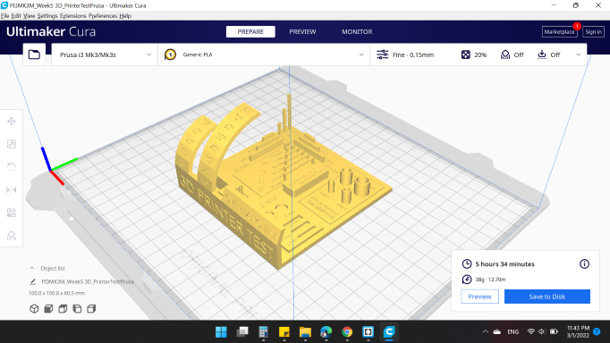
Here's the results.
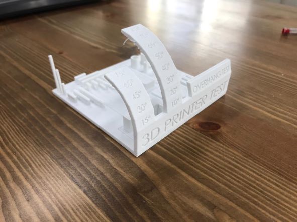
All print settings are correct, and observed that after the angle 60, there is some strings.
That's normal, because over angle 60, we need support to carry the part.
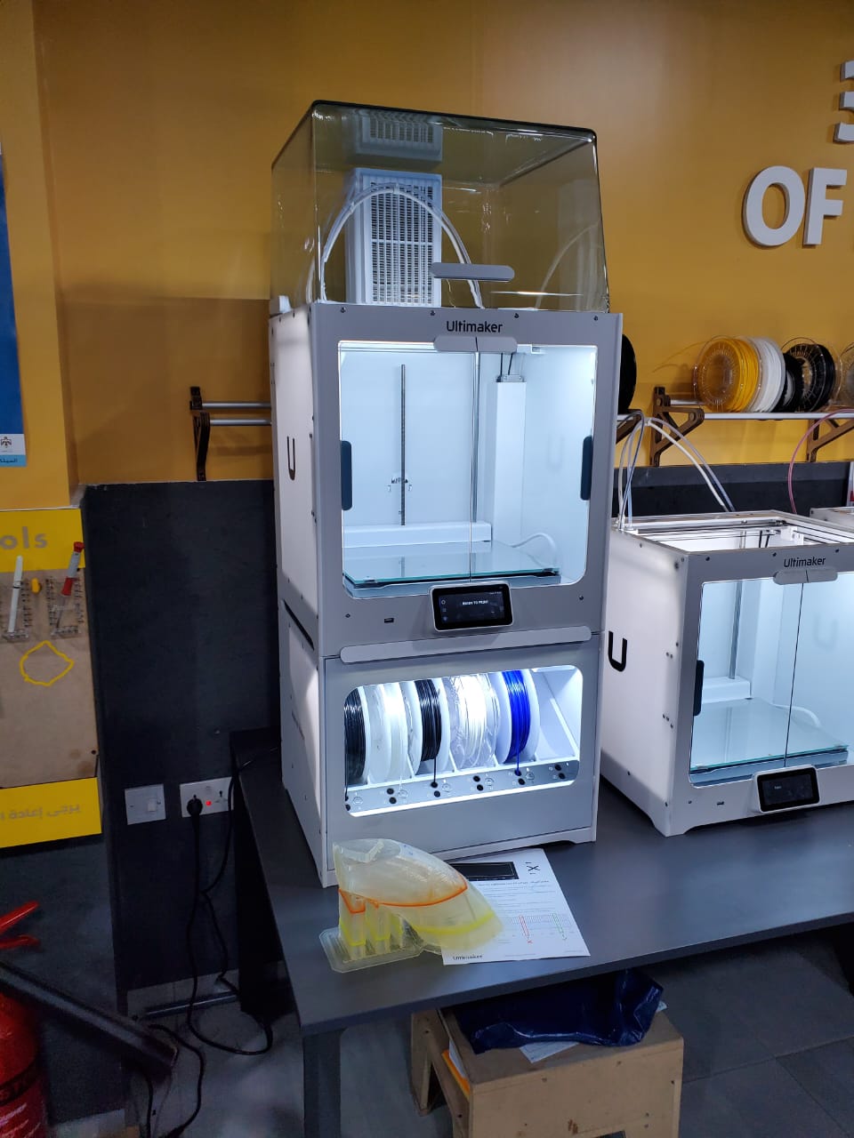
FDM / Ultimaker S5

Our second printer is Ultimaker S5
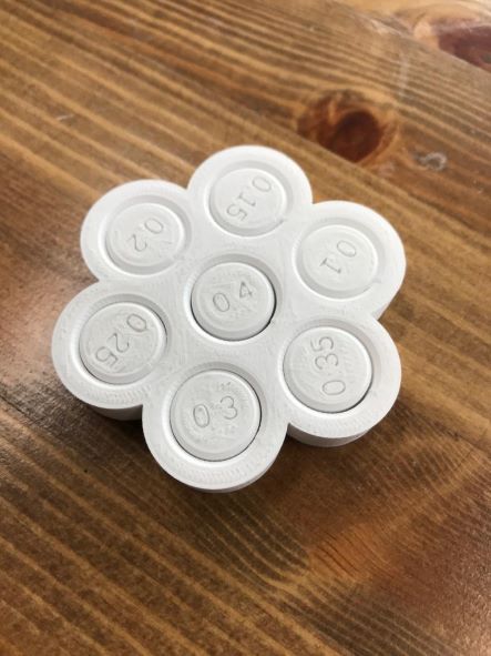
We did a Customizable 3D Clearance Test to measured the clearance.
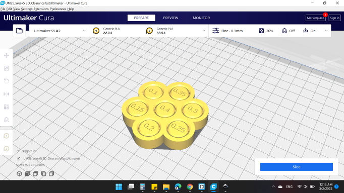
All settings have been made as defaults, and here's the result.
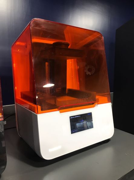
SLA / Form 3B+

Our third printer is Form 3B+.
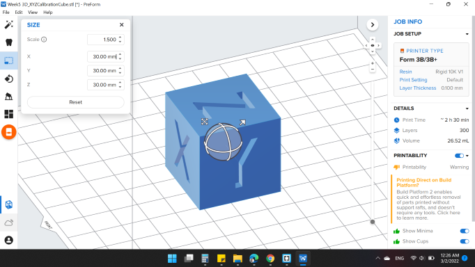
We did a XYZ Calibration Cube to measured the tolerance.
We raised up the scale to 1.5 in order to become 30 mm.
And applied Auto Generate Support.
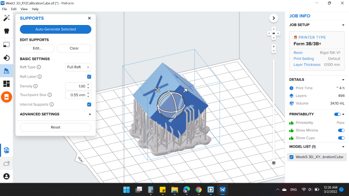
Here's the result.
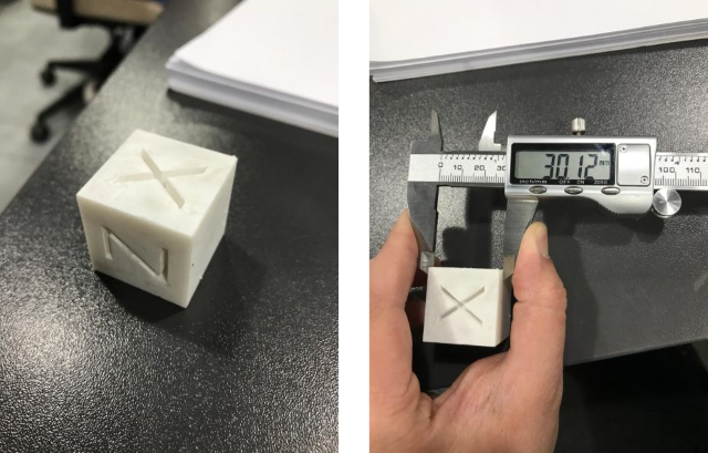
The cube is 30 mm dimensions, we got 30.12 mm when we measured with the caliper. That means tolerances by 0.12.
Delta WASP 3MT INDUSTRIAL 4.0

Techworks has a very large printer and its movement mechanism is awesome, which is Delta WASP 3MT INDUSTRIAL 4.0.
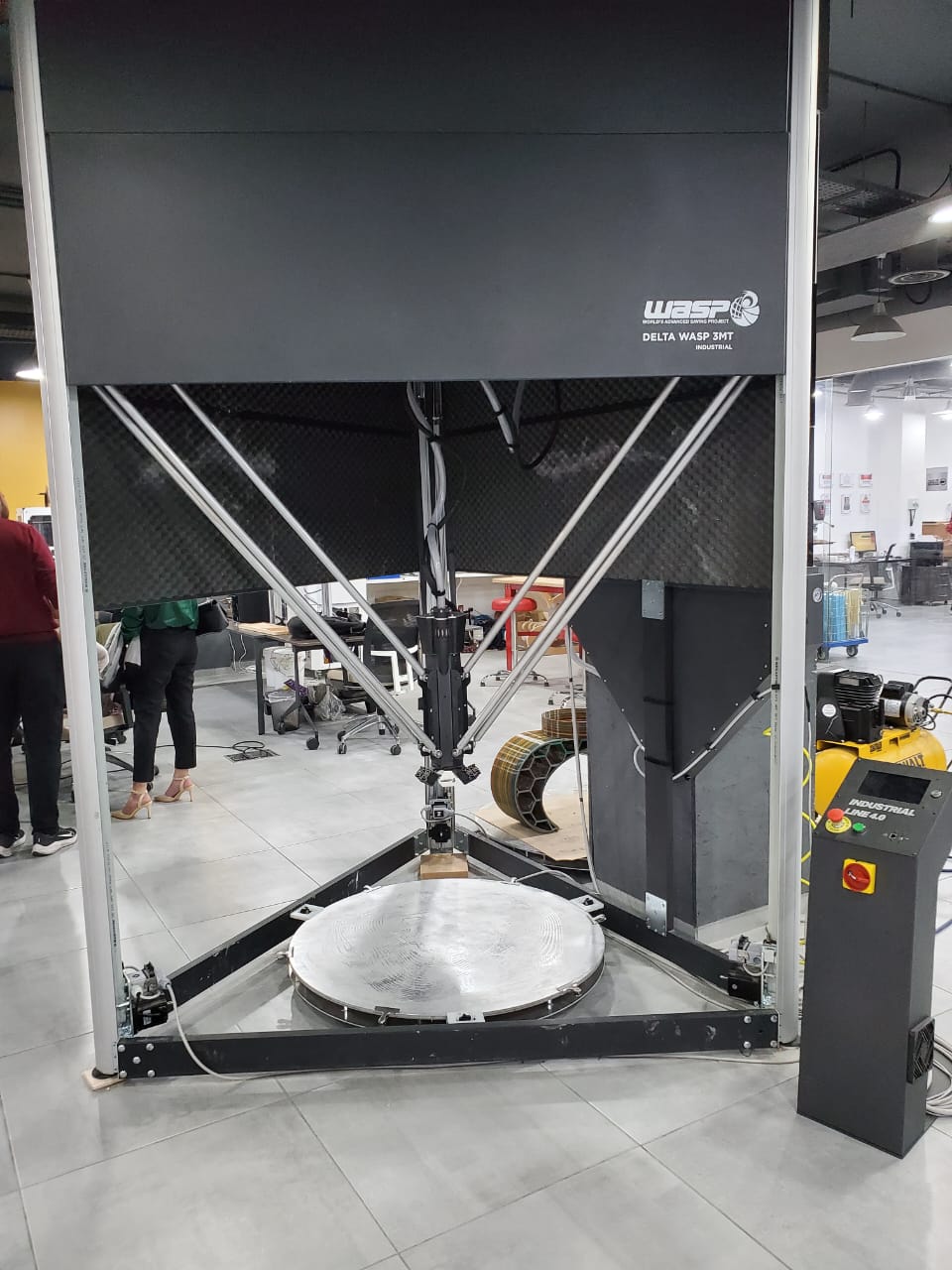
We wanted to see how it works, so the team helped us and showed us the process.
The slicer software it's special for the printer and can't be download unless you have the machine. Which is  .
.
We drew a cylinder using a CAD software, then exported as stl format, and imported in Simplify3D slicer.
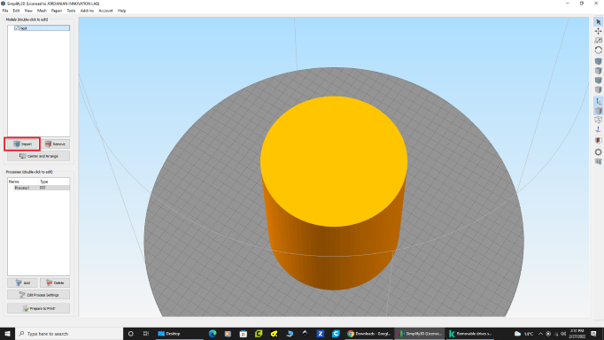
From Processes I double clicked on it to edit.
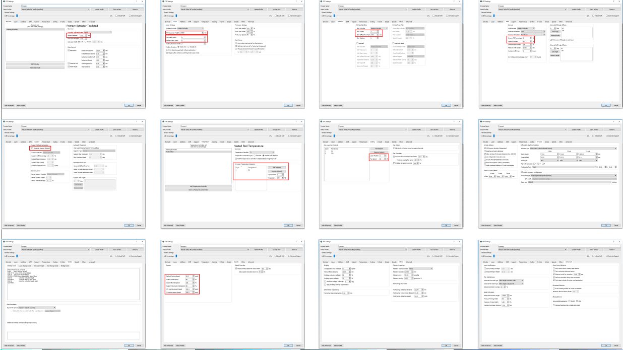
The print settings are:
- Extruder
- Nozzel Diameter: 3 mm.
- Layer
- Primary Layer Height: 1 mm.
- Top Layer Height: 0.
- Bottom Layer Height: 0.
- Additions
- Skirt Layers: 1.
- Skirt Offset From Part: 5 mm.
- Infill
- Interior Fill Percentage: 0 %.
- Outline Overlap: 20 %.
- Support
- Generate Support Material: "NO".
- Temperature
- Temperature: 200 C.
- Cooling
- Fan Speed: 60 %.
- Speeds
- Default Printing Speed: 40 mm/s.
From Prepare to Print!, you can observe your model and how long will it take to print.
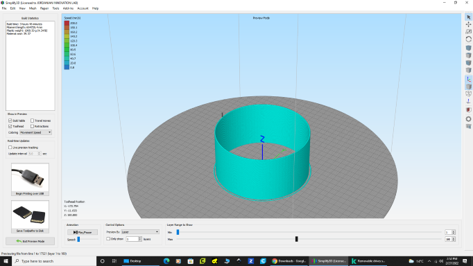
Here's the printer progress.
And here's the print : ).
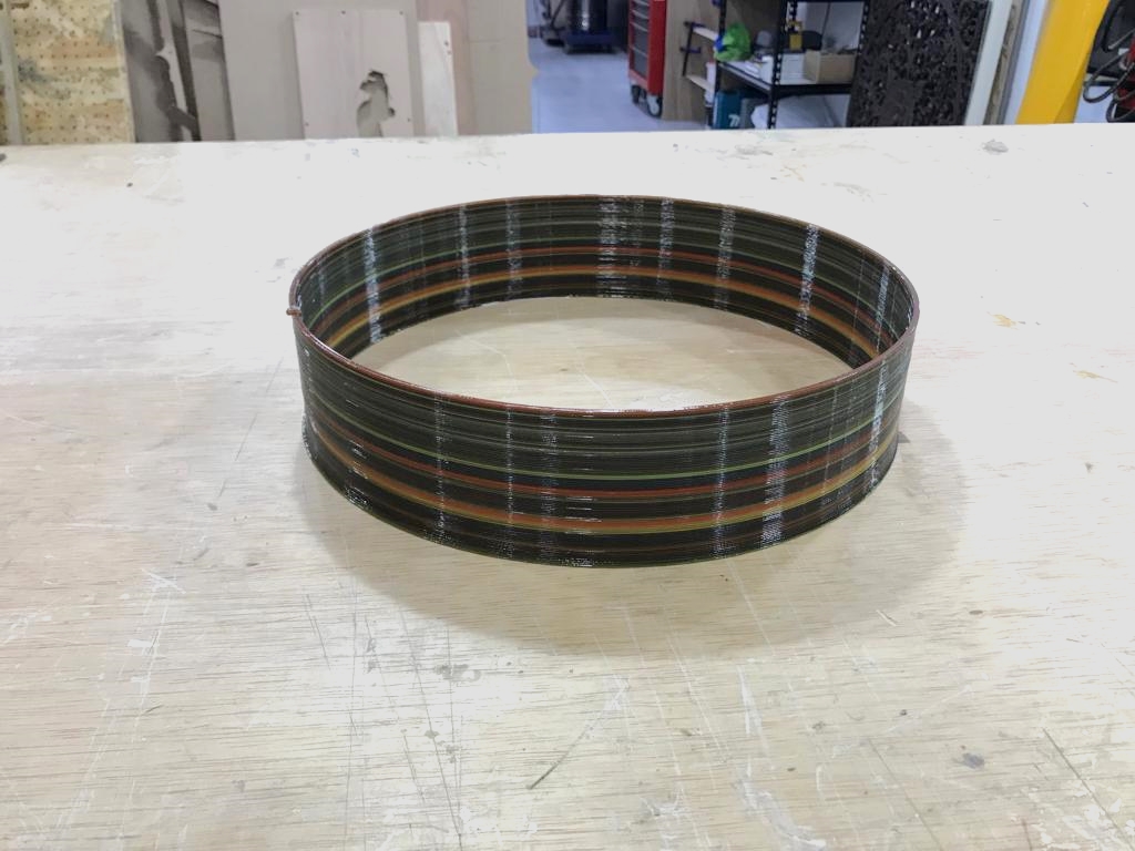
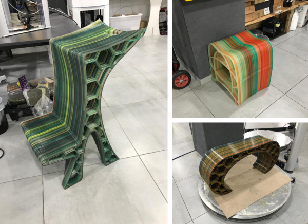
There was a workshop, and here are some models that have been printed.
Individual Assignments
FDM / Original Prusa i3 MK3/S
Regarding the individual assignment, I decided to make something nice using Fusion 360 and  as to learn about it.
Autodesk meshmixer is a fantastic free software for creating and manipulating 3D files for 3D printing. Whether you need to clean up a 3D scan, do some 3D printing or design an object, meshmixer can help.
So, let's start first with my friend Fusion 360.
Usually when we want to draw a symmetrical figure on an one axis, we go with revolve option.
So, I started drawing a cross section for the model.
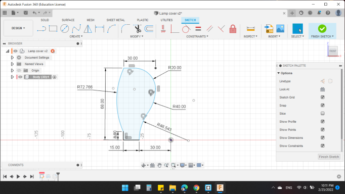
Then, by revolve option, I revolved by 360 degree.
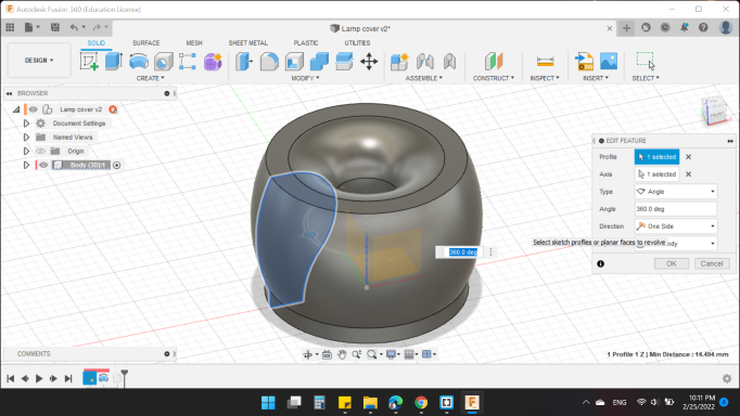
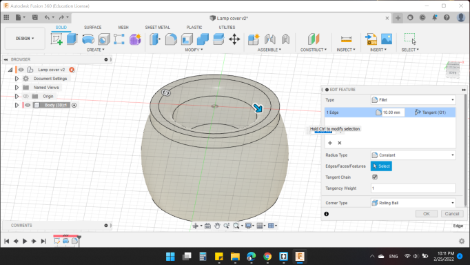
And to make the shape beautiful and free from sharp edges, I added fillet to the bottom.
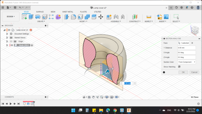
Here's the model in section view.
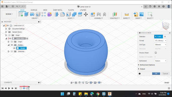
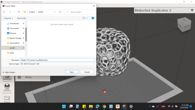
Last but not least, saved as STL format.
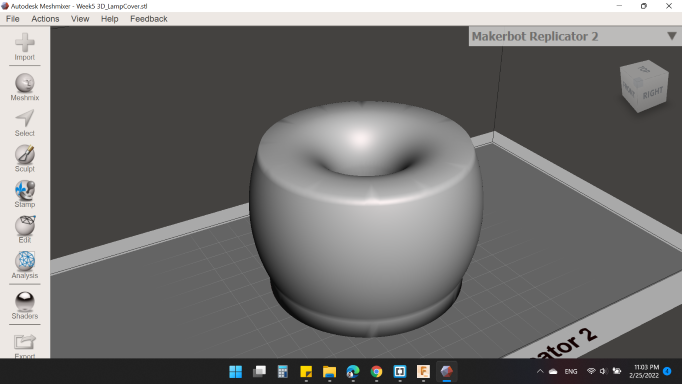
After prepared the stl file, opened Meshmixer software
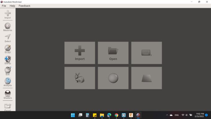
From import, I opened the model as stl format.
I wanted to emptying the model, so from Sculpt > Brushes > Reduce.
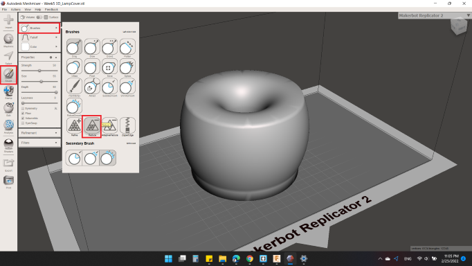
I started clicked on the model several times as the video below:
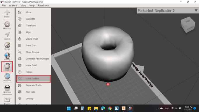
Then, from Edit > Make Pattern we can choose the emptying shape and make some modifications.
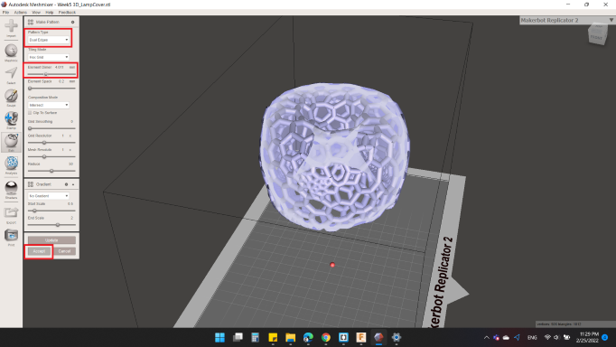
From Pattern Type I choose Dual Edges, and raised up the thickness by Element Dimensions.
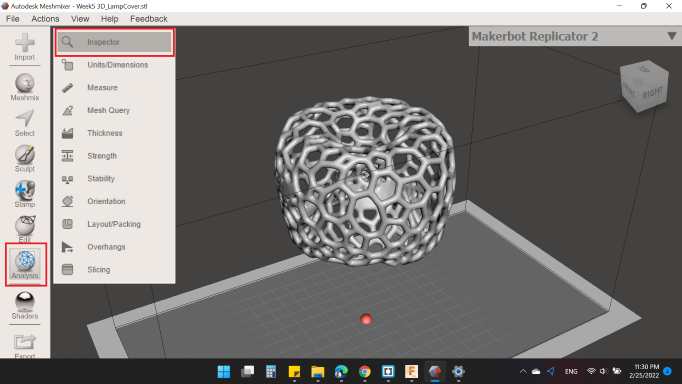
Before finished the process, to make sure that your model is correct and there is no damage, I clicked on Analysis > Inspector, then Auto Repair All.
Last but not least, Export.
Here's my design in 3D view, you can rotate it and see it close.
The process of obtaining the model is almost complete, one last thing is slice the model by a slicing software. Of course  is the best one to perform the job.
Cura is an open source slicing application for 3D printers.
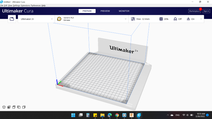
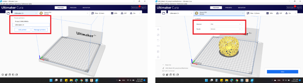
First at all, I opened the model and selected the printer that I want to use, last choose the Material PLA and Nozzle 0.4mm.
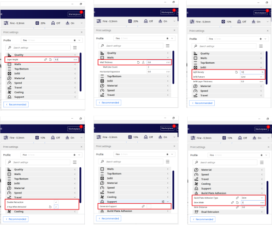
Nest, the print settings:
- Quality
- Layer Height: 0.3 mm. (The height of each layer in mm)
- Walls
- Wall Thickness: 0.8 mm. (The thickness of the walls in the horizontal direction)
- Infill
- Infill Density: 10 %. (Adjusts the density of infill of the print)
- Infill Pattren: Grid. (The pattern of the infill material of the print)
- Travel
- Enable Retraction: "YES". (Retract the filament when the nozzle is moving over a non-printer area)
- Z Hop When Retracted: "YES". (The build plate is lowered to create clearance between the nozzle and the print)
- Support
- Generate Support: "NO". (Generate structures to support parts of the model which have overhangs) / "No" because my model is self supporting itself.
- Build Plate Adhesion
- Build Plate Adhesion Type: Brim. (Different options that help to improve both priming your extrusion and adhesion to the build plate. Brim adds a single layer flat area around the base of your model to prevent warping)
- Brim Width: 3 mm. (The distance from the model to the outermost btim line)
My model needs:
- 3 hours 33 minutes
- 29g
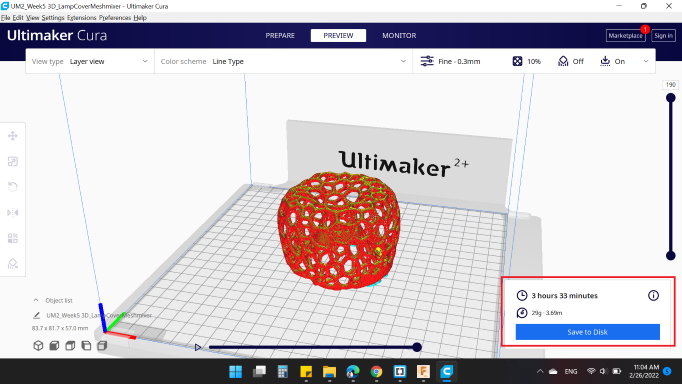
Finally, saved the g-code.
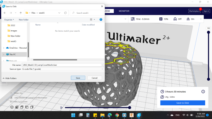
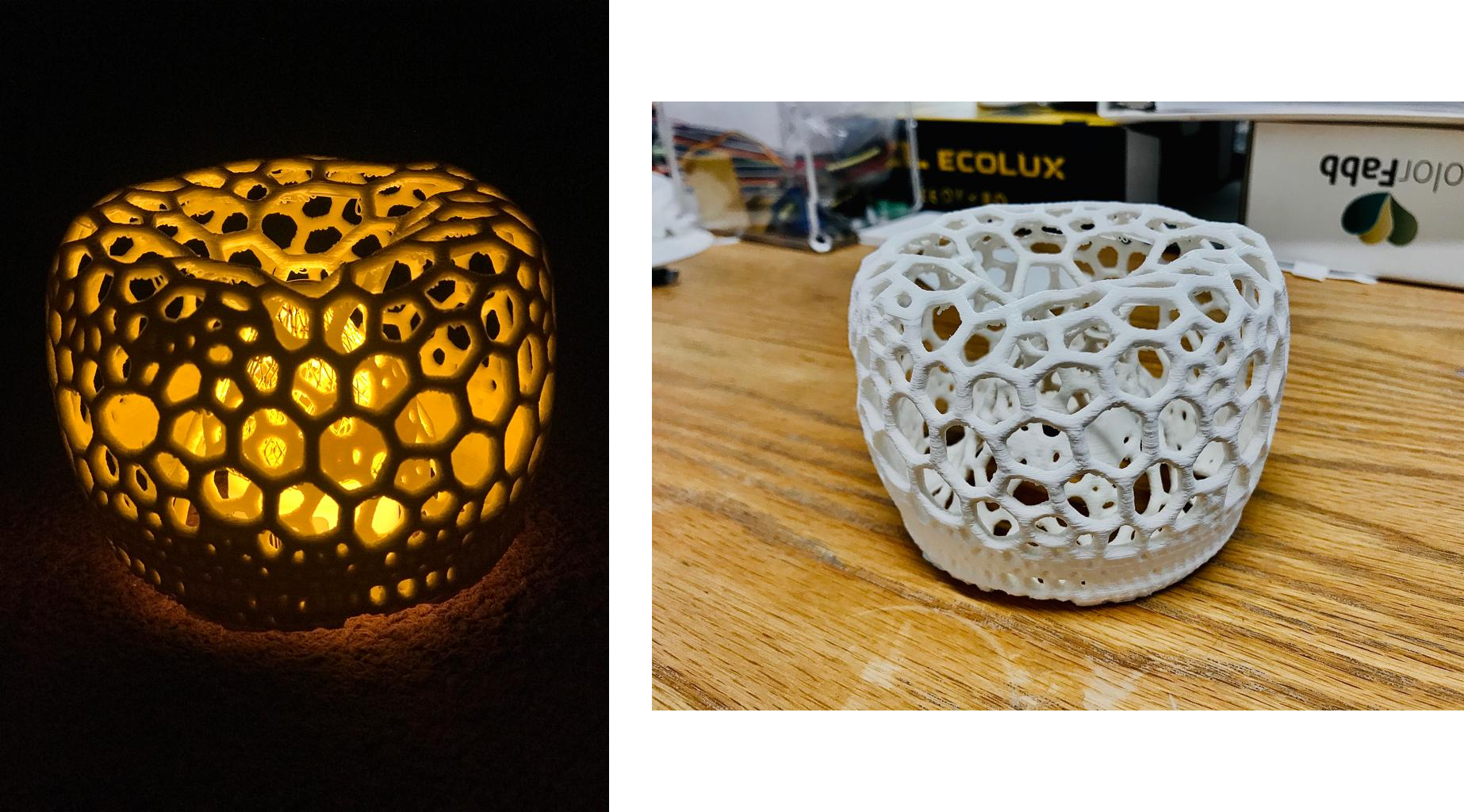
Here's my Lamp Cover : ).
FDM / Ultimaker S5
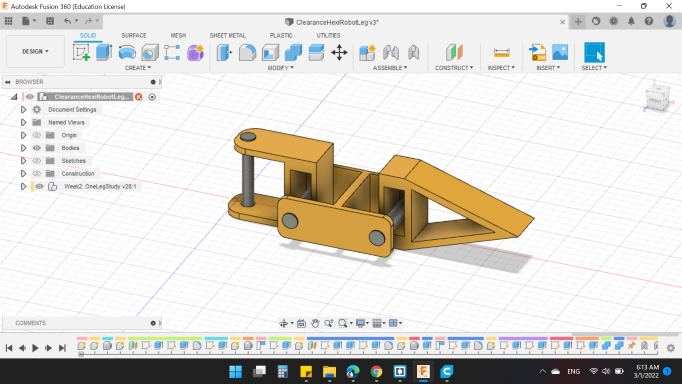
I wanted to print the HexiRobot leg that I designed in CAD week, so that I could visualize the movement and thus move forward, but I wanted to add something new for me.
I wanted to print the model in two different colors using Ultimaker S5.
I modified some simple things in the design, where the servo motors were replaced to rods, which performs the same job for now.
Because I want to print each part in color, I saved the Links together, and I saved the Rods separately (Actually I should save the rods together but when I designed them, I forget to create a new comonent contain the 3 rods)
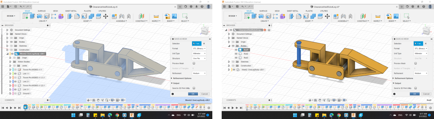
Next, I opened Cura and import the 4 files (1 Links, 3 Rods).
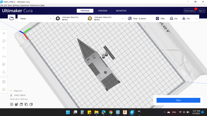
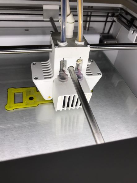
Then, I changed the material type and color for both nozzles.
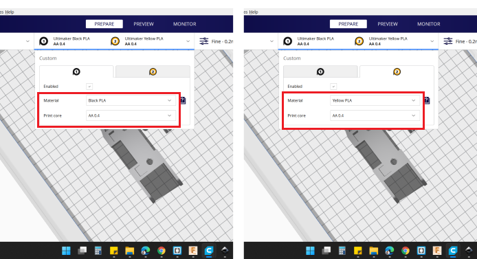
Next, right click on the Links to select the nozzel with the color, which was Extruder 2: Yellow PLA.
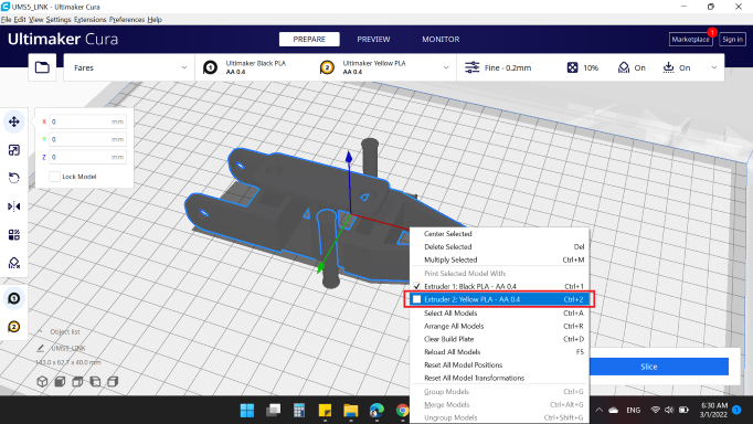
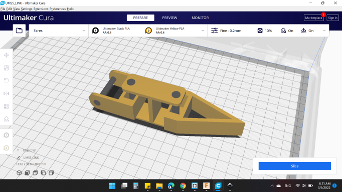
Then, I selected all parts, and right click to Merge Models. Here you will notice that the parts will be installed in the same position you drew them.
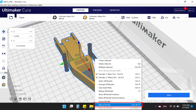
Here's the results.
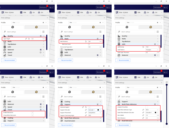
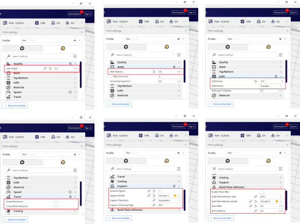
Next, to print settings.
Because here the 2 extruder are use, 2 different settings will be applied.
Extruder 1
- Quality
- Layer Height: 0. mm.
- Walls
- Wall Thickness: 0.8 mm.
- Infill
- Infill Density: 10 %.
- Infill Pattren: Grid.
- Travel
- Enable Retraction: "YES".
- Z Hop When Retracted: "YES".
- Support
- Generate Support: "YES".
- Build Plate Adhesion
- Build Plate Adhesion Type: Brim.
- Brim Width: 3 mm.
Extruder 2
- Quality
- Layer Height: 0. mm.
- Walls
- Wall Thickness: 0.8 mm.
- Infill
- Infill Density: 10 %.
- Infill Pattren: Grid.
- Travel
- Enable Retraction: "YES".
- Z Hop When Retracted: "YES".
- Support
- Generate Support: "YES".
- Build Plate Adhesion
- Build Plate Adhesion Type: Brim.
- Brim Width: 3 mm.
My model needs:
- 6 hours 5 minutes
- 40 g
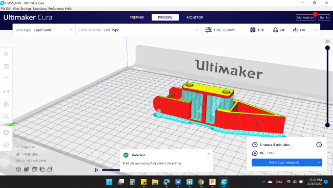
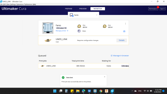
I clicked on Print Over Network as it has a Wi-Fi feature.
Here in Monitor window, you can observe you model and open the Camera.
After I sent the form to the printer, the printer displayed a notification about Calibrate XY Offset.
Everytime you use the 2 extruder, you should calibrated.
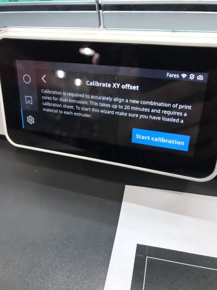
You can take advantage of the Ultimaker Support.
Click on the photo below, to open the pdf file to print the sheet:
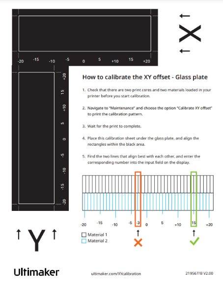
To start the calibration:
- Go to System > Maintenance > Calibration > Calibrate XY offset
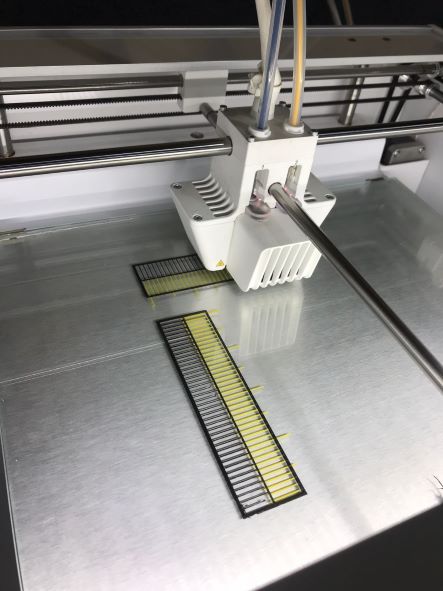
- The Ultimaker S5 will now print a grid structure on the build plate. Wait until it is finished
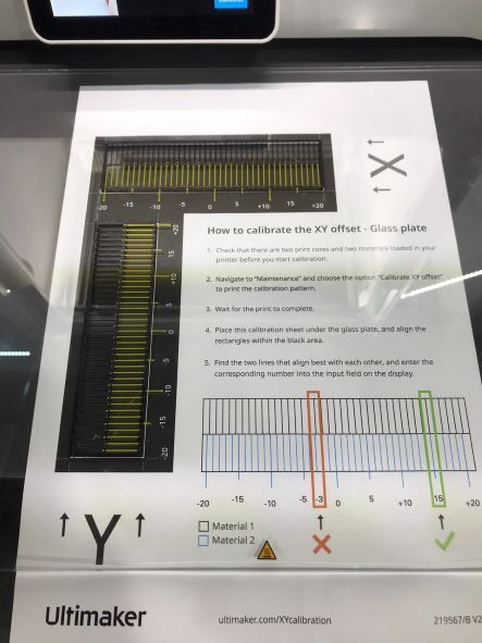
- Once the Ultimaker S5 has cooled down, remove the glass plate from the printer and place it on the XY calibration sheet. Ensure the printed grid it is exactly placed on the two rectangles on the sheet
- Find the aligned lines on the printed X grid and look which number belongs to these lines. Enter this number as the X offset value on your Ultimaker S5
- Find the aligned lines on the printed Y grid and look which number belongs to these lines. Enter this number as the Y offset value on your Ultimaker S5
After the calibration finished, I returned to my model.
Here's the printer begins.
And finally, my model is done : ).

SLA / Form 3B+
I decided to make another model and printed using SLA technology.
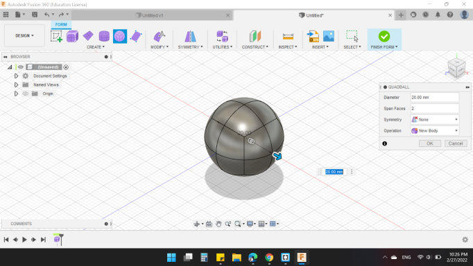
So again, I'm back on my favorite CAD software "Fusion360" : ).
I went to Form design and start with Quadball shape with 20mm diameter as the body of my design.
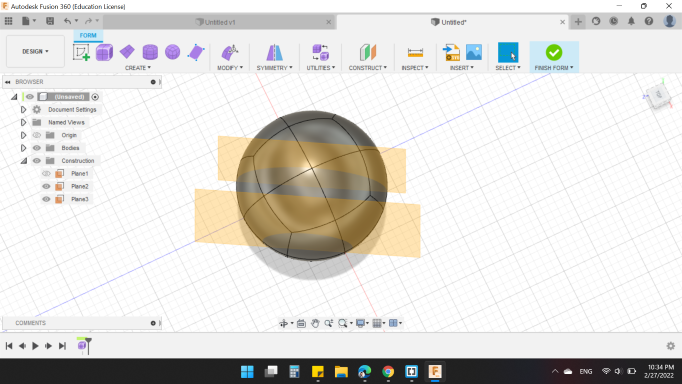
Then, created a Plane at angle from Z Axis and Offset Plane from that.
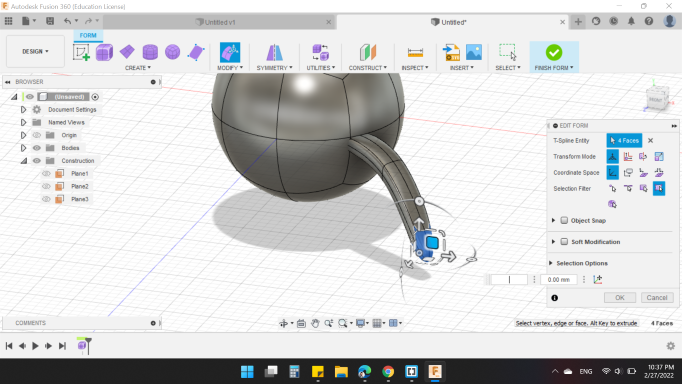
Next, to make legs, I used Box shape form the new plane, and pulled with change surface shape to looks like a leg.
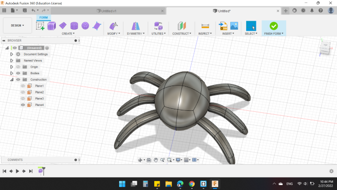
For the rest of the legs, I drew the middle leg, then a Mirror for the first leg from X,Z plane, and Mirror for the 3 legs from the left side to the right side to looks like below.
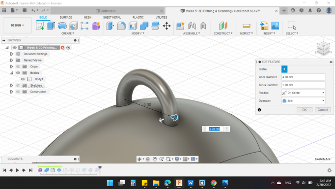
I decided to make an upper loop so I could hang it up.
From Torus with 4mm Inner diameter and 1 mm Torus diameter.
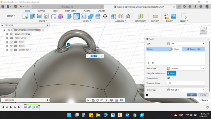
And support the whole legs and ring with 0.5mm Fillet.
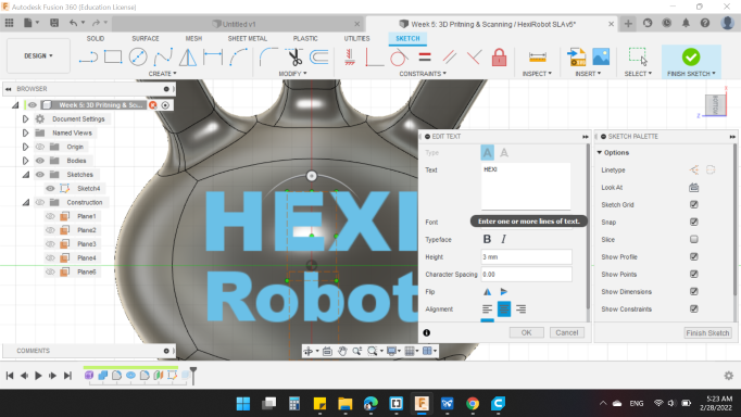
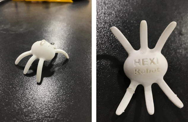
Also, I added text on the lower body.
Finally, Extruded backward to cut the body.
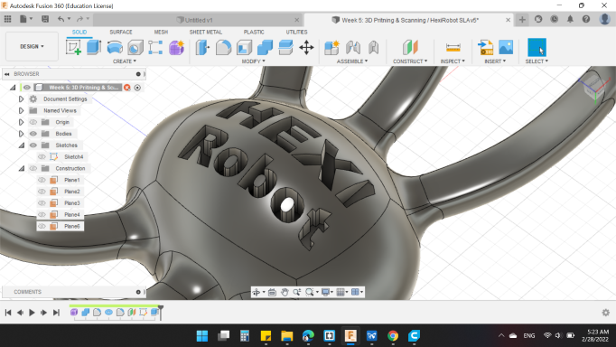
Here's my design in 3D view, you can rotate it and see it close.
CAM software for Form 3B+ printer is ![]() PreForm .
PreForm .
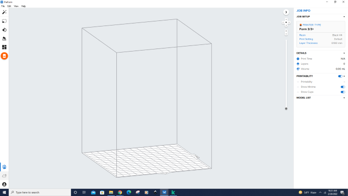
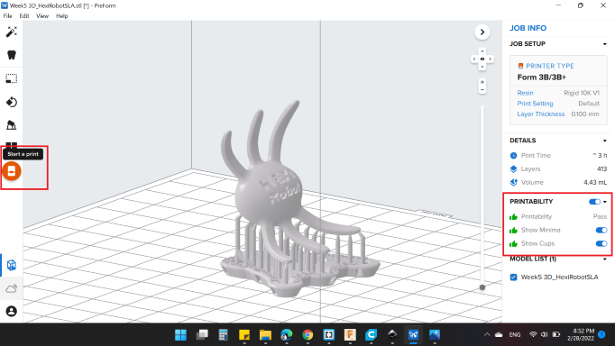
First, I opened the model.
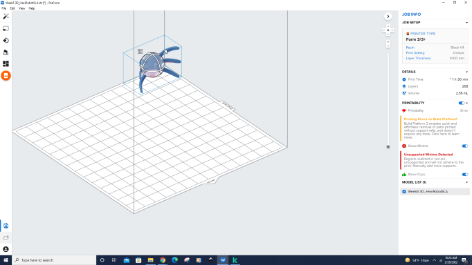
Then, rotate the model to be in an angle that reduce the surface area touched the bed plate.
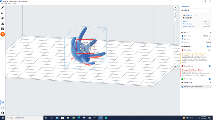
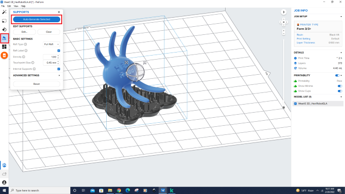
Then from Support on the left, I clicked on Auto Generate All to create support.
At the right side, from JOB INFO> JOB SETUP here all required settings.
- Choose Printer Type: Form 3B/3B+
- Choose Material: Rigid 10K
- Choose Layer Thickness: 0.100 mm
- Choose Print Settings: Defualt
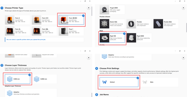
Last but not least, make sure that PRINTABLITY settings are all green "Thumb Up".
Finally, Start a print.
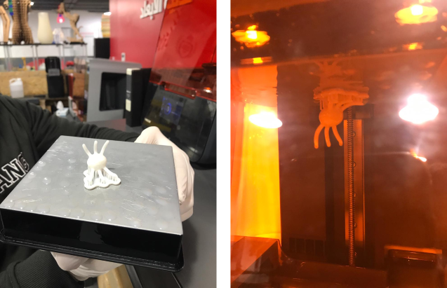
Now, Let's go to use the printer!
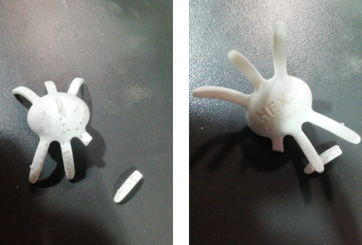
After send the file to the printer and a few hours have passed, here's the model :)
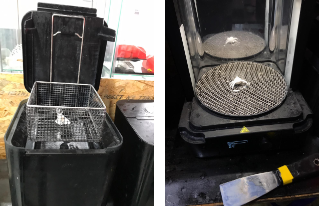
The model also will definitely need some Post-Processing to remove the support and clean the model with some ethanol.
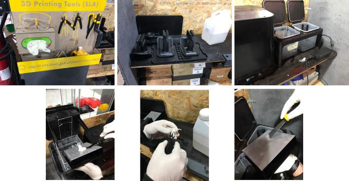
With the Washing & Curing Machines, I completed the Post Processing
Unfortunately, one of the model legs broke : ( , I will glued it.
Here's the final results : ).
3D Scanning / Sense
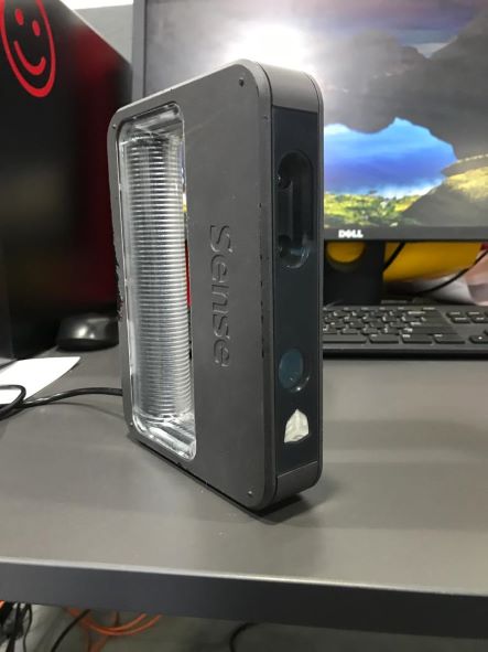
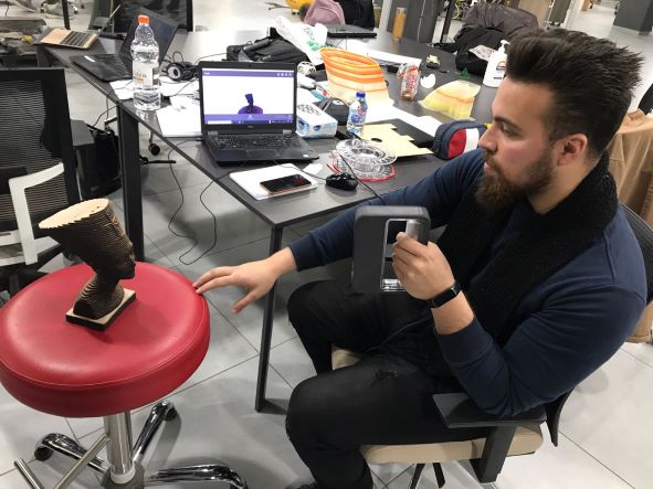
We have 3D Sense Scanner by 3D Systems
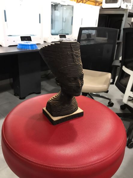
I found a nice object in the lab to scan. It's Nefertiti.
I chose Head because I was only going to scan his head, then I pressed start scan. It gives you a 3 seconds timer beofre it starts capturing.
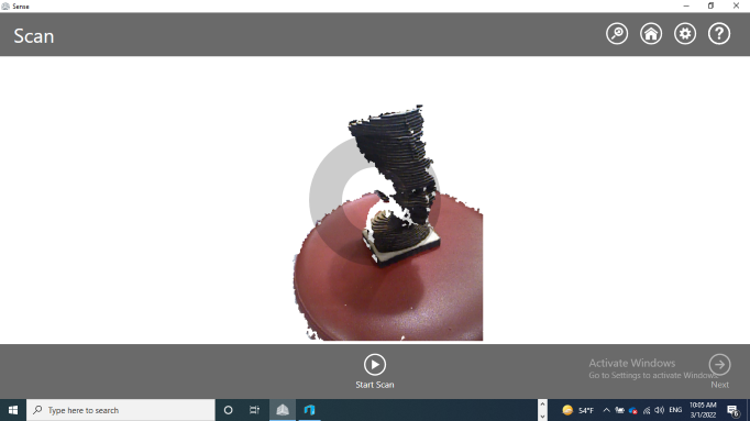
I started slowly rotating the chair to fill the white gaps that shows in the software.
My finished scan looked really good, so I pressed Soldify to make it into a solid.
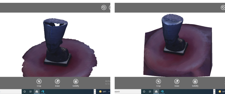
Then, I observed that the base are too large, so I used Trim tool to reduced and modified it.
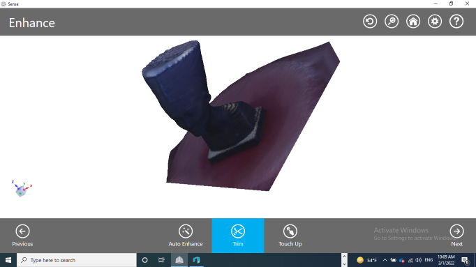
Here's the final look. Last step, I saved as STL format.
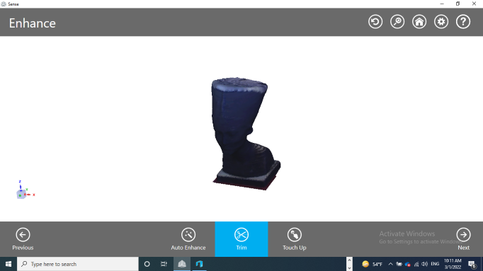
Here's my design in 3D view, you can rotate it and see it close.
You can download my files here: