Networking and communications
Group assignment
Send a message between two projects Overview of Chip to Chip Communication Protocols Nearly all PCBs contain multiple ICs, which necessary to the boards to communicate with each other, usually users need data transfer along multiple PCBs. SPI, I2C, and UART are the most often used protocols in these kinds of connections. Here, some of these protocols' main characteristics and certain design principles for ensuring high-fidelity communication are presented.
SPI (Serial Peripheral Interface)
he SPI is a high-speed synchronous serial input/output port that allows a serial bit stream of programmed length (2 to 16 bits) to be shifted into and out of the device at a programmed bit-transfer rate. The SPI is normally used for communication between the device and external peripherals. Typical applications include interface to external I/O or peripheral expansion via devices such as shift registers, display drivers, SPI EPROMS, and analog-to-digital converters .source
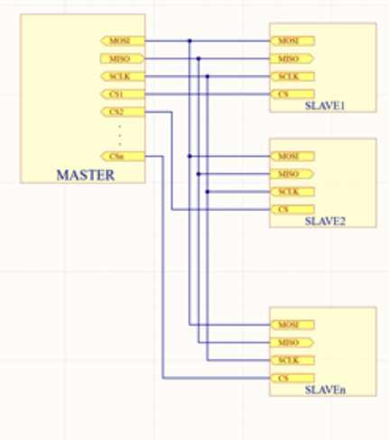
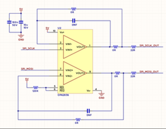
Multiple slaves can communicate with one master, but each slave needs a chip select signal. This indicates that the master will need n+3 pins for every n slaves. SPI communication may occur at speeds of up to 100MHz. However, various extra circuitry may be required to communicate quickly. Overshoot and ringing are the high speed SPI signal's most typical issues. By adding a modest series resistance to the signal route, this issue may be solved easily. The output and clock lines should be buffered if the communication distance is great. Below is an example buffer circuit: In the image below, n is depicted.
I2C (Inter-Integrated Circuit)
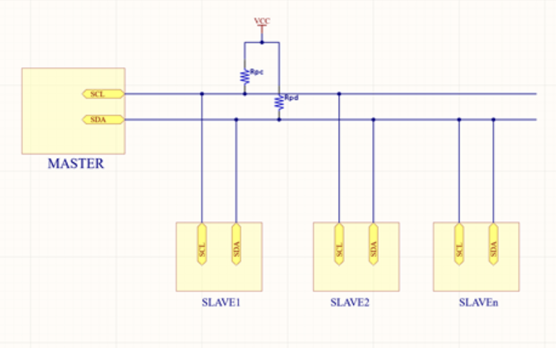
The I2C bus consists of two signals − SCL and SDA. SCL is the clock signal, and SDA is the data signal. The current bus master always generates the clock signal. Some slave devices may force the clock low at times to delay the master sending more data (or to require more time to prepare data before the master attempts to clock it out). This is known as “clock stretching”.
UART (Universal Asynchronous Receiver Transmitter):
Two chips are linked directly via the UART protocol. One chip's Tx is linked to the other's Rx, and vice versa. Because this protocol is not scalable, only two chips can communicate with one another over a single UART line. The following is a block diagram of UART communication:
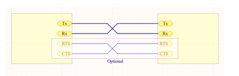
Since there is no clock transmitted, the receiving chip must be aware of the speed of the other chip's transmission. The UART line should have a series resistor added, similar to how SPI is done to account for overshoot and ringing. The single-ended nature of the signals makes them more susceptible to noise, particularly over long distances. To increase the integrity of the connection, two additional signals, CTS (Clear to Send) and RTS (Request to Send), are occasionally introduced. source
Group assignment
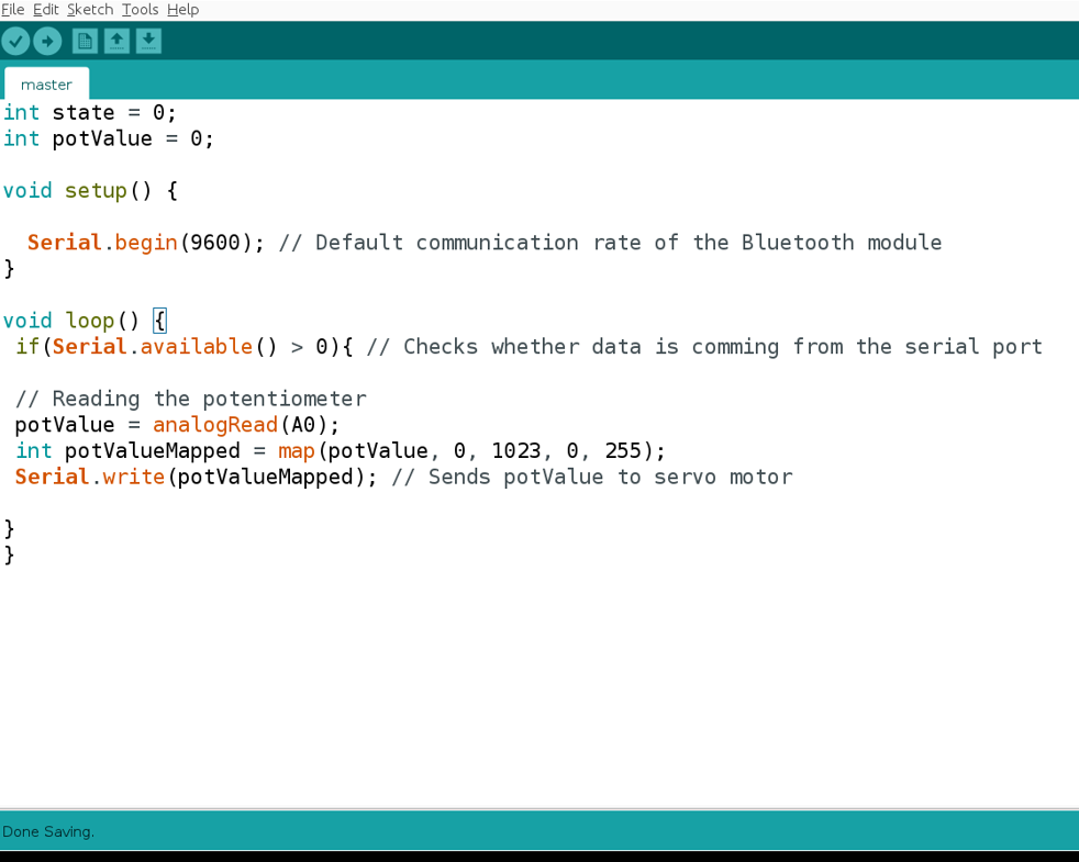
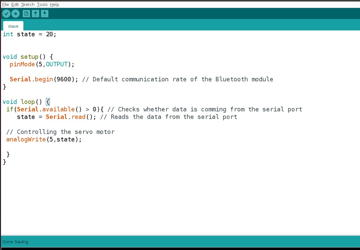
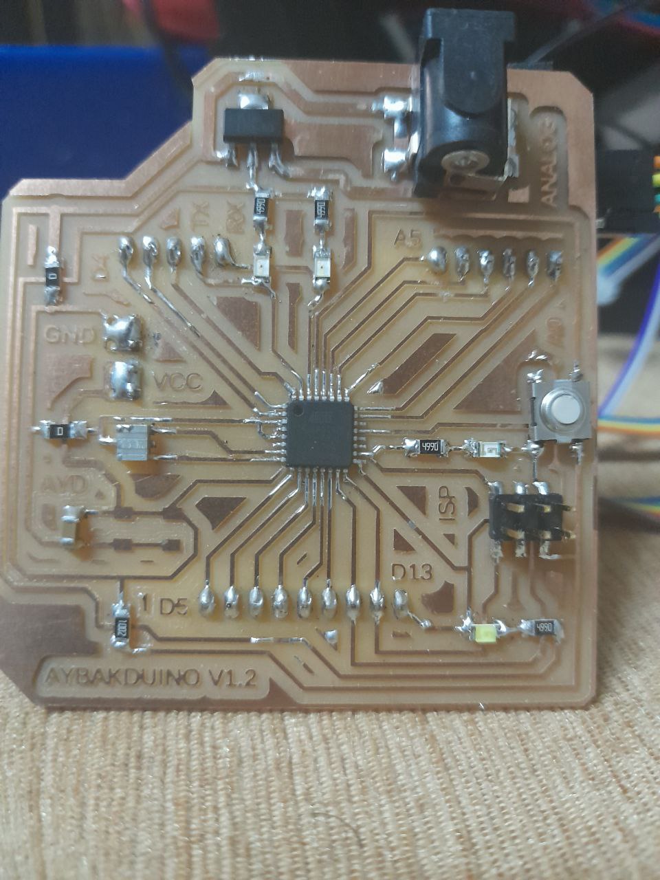
We work in group assignment to control led intensity with potentiometer, the led connected with slave controller board my board and potentiometer with master controller board amin-yousef Wiring connect the potentiometer signal with pin number A0 in master board and connect the led with pin number 5 in slave board, finally connect TX in master board with RX in slave board and RX in master board with TX in slave board.
File to Download.
Note : the baud rate must be the same in master and slave board Code for Master board
Code for Slave board.
Hero Shot !
Wireless communication (Bluetooth)
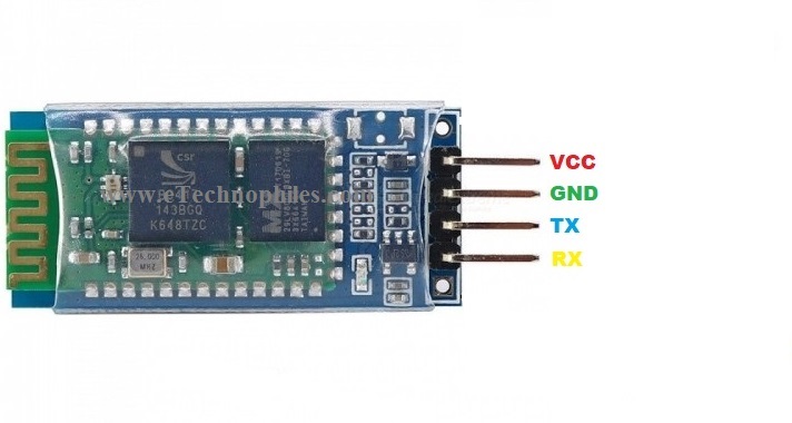
this week i use HC 06 bluetooth module which is a "Bluetooth module designed for establishing short range wireless data communication between two microcontrollers or systems. The module works on Bluetooth 2.0 communication protocol and it can only act as a slave device. This is cheapest method for wireless data transmission and more flexible compared to other methods and it even can transmit files at speed up to 2.1Mb/s. HC-06 uses frequency hopping spread spectrum technique (FHSS) to avoid interference with other devices and to have full duplex transmission. The device works on the frequency range from 2.402 GHz to 2.480GHz." reference
HC-06 Features and Electrical characteristics
- Bluetooth protocol: Bluetooth V2.0 protocol standard
- Band: 2.40GHz—2.48GHz, ISM Band
- Receiver sensitivity: -85dBm
- USB protocol: USB v1.1/2.0
- Operating voltage range:+3.3V to +6V
- Operating temperature range: -20ºC to +55ºC
- Operating Current: 40mA
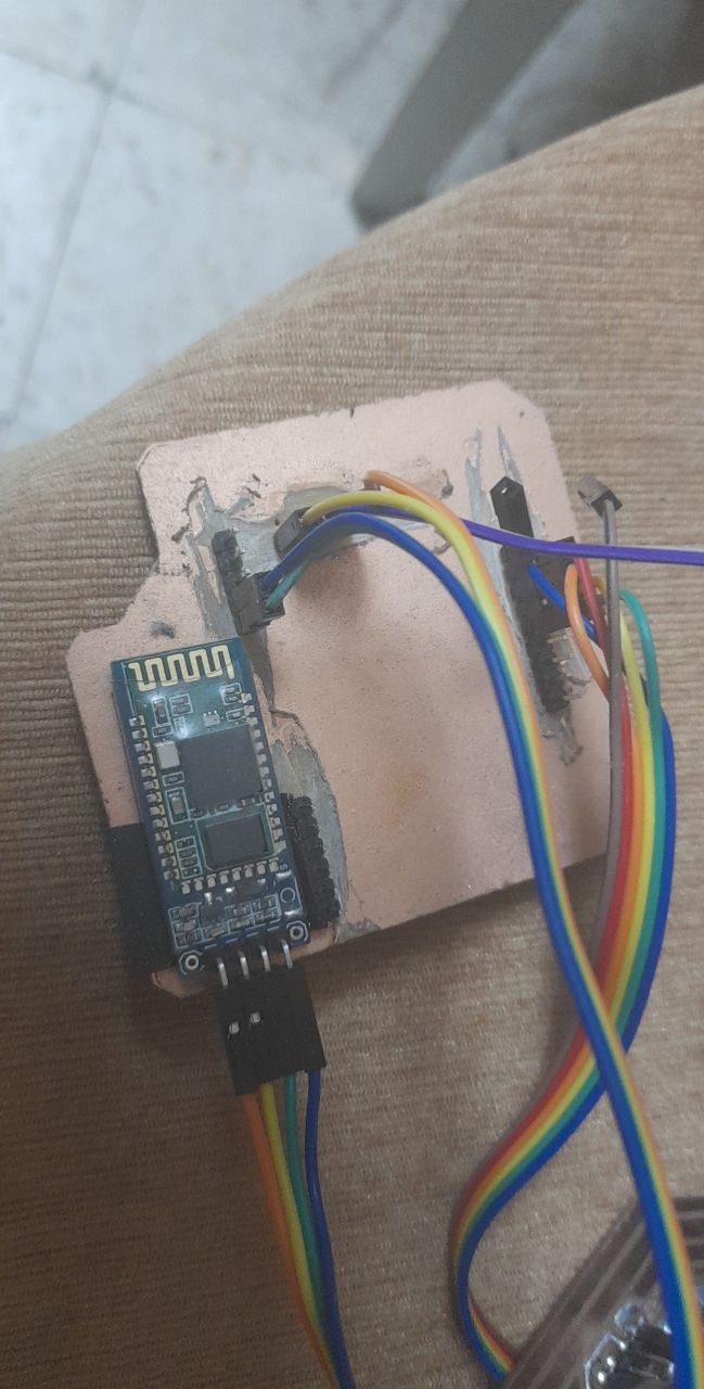
here is the pinout for the HC 06 bluetooth module and I will connect the Tx pin to the RX pin on Aybakduino board and the RX oin to the Tx pin on Aybakduino board.
| Aybakduino | HC 06 bluetooth module |
|---|---|
| VCC | VCC |
| GND | GND |
| TX | RX |
| RX | TX |
down below you will see the code to test the bluetooth connection and the main purpose for this code is to test the stepper motors for my final project
// Define pin connections & motor's steps per revolution
const int dirPin = 5;
const int stepPin = 6;
const int dirPinA = 7;
const int stepPinA = 8;
const int dirPinB = 9;
const int stepPinB = 10;
const int dc_enable1 = 11;
const int dc_enable2 = 12;
const int stepsPerRevolution = 200;
char Incoming_value ;
void setup()
{
	Serial.begin(9600);
// Declare pins as Outputs
pinMode(stepPin, OUTPUT);
pinMode(dirPin, OUTPUT);
pinMode(stepPinA, OUTPUT);
pinMode(dirPinA, OUTPUT);
}
void loop()
{

 if(Serial.available() > 0)
{
	Incoming_value = Serial.read();
// Set motor direction clockwise

if(Incoming_value == '0') {
	Incoming_value = Serial.read();
// Spin motor slowly
for(int x = 0; x < stepsPerRevolution; x++)
{

			 digitalWrite(dirPin, HIGH);
 // digitalWrite(dirPin, HIGH);
	digitalWrite(stepPin, HIGH);
	delayMicroseconds(1000);
	digitalWrite(stepPin, LOW);
	delayMicroseconds(100);
}

}
// Set motor direction counterclockwise

if(Incoming_value == '1') {
// Spin motor quickly
	Incoming_value = Serial.read();
for(int x = 0; x < stepsPerRevolution; x++)
{
 digitalWrite(dirPin, LOW);
	digitalWrite(stepPin, HIGH);
	delayMicroseconds(1000);
	digitalWrite(stepPin, LOW);
	delayMicroseconds(100);
} }
if(Incoming_value == '2') {
	Incoming_value = Serial.read();
// Spin motor slowly
for(int x = 0; x < stepsPerRevolution; x++)
{

			 digitalWrite(dirPinA, HIGH);
 // digitalWrite(dirPin, HIGH);
	digitalWrite(stepPinA, HIGH);
	delayMicroseconds(1000);
	digitalWrite(stepPinA, LOW);
	delayMicroseconds(100);
}

}
// Set motor direction counterclockwise

if(Incoming_value == '3') {
// Spin motor quickly
	Incoming_value = Serial.read();
for(int x = 0; x < stepsPerRevolution; x++)
{
 digitalWrite(dirPinA, LOW);
	digitalWrite(stepPinA, HIGH);
	delayMicroseconds(1000);
	digitalWrite(stepPinA, LOW);
	delayMicroseconds(100);
} }
if(Incoming_value == '4') {
	Incoming_value = Serial.read();
// Spin motor slowly
for(int x = 0; x < stepsPerRevolution; x++)
{

			 digitalWrite(dirPinB, HIGH);
 // digitalWrite(dirPin, HIGH);
	digitalWrite(stepPinB, HIGH);
	delayMicroseconds(1000);
	digitalWrite(stepPinB, LOW);
	delayMicroseconds(100);
}

}
// Set motor direction counterclockwise

if(Incoming_value == '5') {
// Spin motor quickly
	Incoming_value = Serial.read();
for(int x = 0; x < stepsPerRevolution; x++)
{
 digitalWrite(dirPinB, LOW);
	digitalWrite(stepPinB, HIGH);
	delayMicroseconds(1000);
	digitalWrite(stepPinB, LOW);
	delayMicroseconds(100);
} }
if(Incoming_value == '6') {

	Incoming_value = Serial.read();

 digitalWrite(dc_enable1, LOW);
	digitalWrite(dc_enable2, HIGH);
	delay(5000);

 }
if(Incoming_value == '7') {

	Incoming_value = Serial.read();

 digitalWrite(dc_enable1, LOW);
	digitalWrite(dc_enable2, LOW);

}
}}
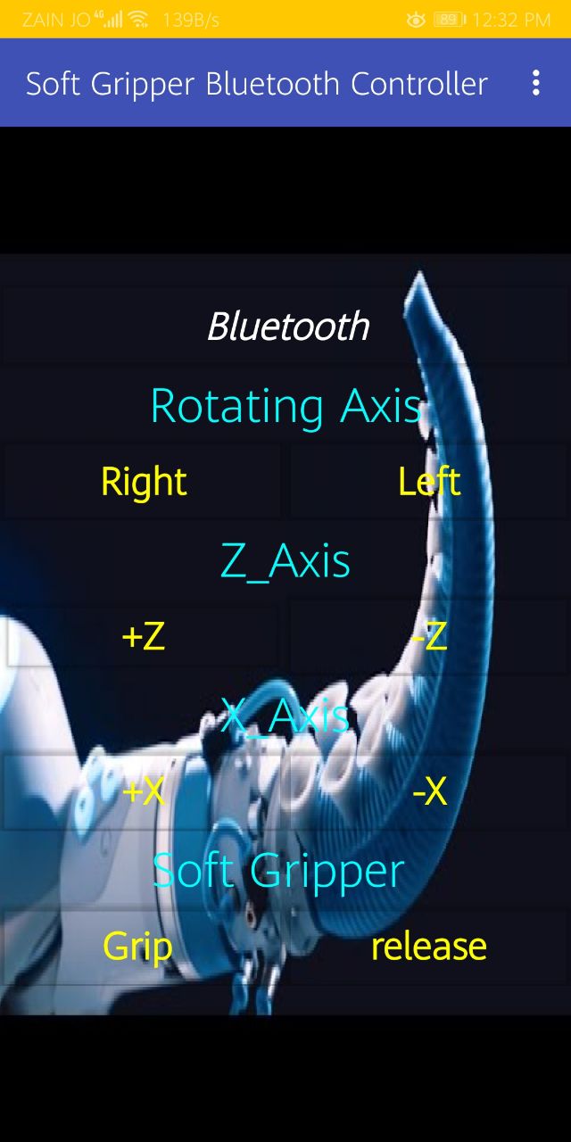
and to send the commands i will use the application that I have designed to control my soft gripper you can see the full documentation for this application here .