Input devices
Group Assignment
- Probe an input device(s)'s analog and digital signals.
- Document your work to the group work page and reflect on your individual page what you learned.
Digital Signal
digital signals are just two-state signals (0,1) when it has the state of 0 that's the means 0V but when the state is 1 that's the means( 1.8V or 3.3v or 5v ) and that depends on the logic voltage on this system .

Encoder
"The rate of an electric motor may be checked using this Encoder Sensor Module Digital Output. This module may be used in conjunction with a microcontroller to detect motor speed, count pulses, and set a position restriction. Any rate meter, in theory, merely monitors the rate at which an event occurs. Typically, this is accomplished by counting the events over a specified time interval (integration interval) and then dividing the number of events by the duration to obtain the rate ""Source
we test the digital encoder sensor which is usually LOW (0V) but when an object is cutting the infrared light the output signal will turn into HIGH (5V). so we connected the decoder to the oscilloscope and We watched the digital signal
Analog Signal
"The signal whose amplitude takes any value in a continuous range is called analog signal. Analog Signals are continuous in nature which vary with respect to time. They can be periodic or non-periodic. Voltage, current, frequency, pressure, sound, light, temperature are the physical variables that are measured with respect to their changes with respect to time to obtain information. When voltage versus time graph is plotted we see curve with continuous values like sine waves."Source

Potentiometer
Potentiometer or variable resistor is a type of position sensor and the working principle of this sensor is basically like a voltage divider so it will give a variable voltage depending on the position of the shaft .

here we tested a potentiometer and we watched the signal which is varying based on the shaft position
Individual Assignment
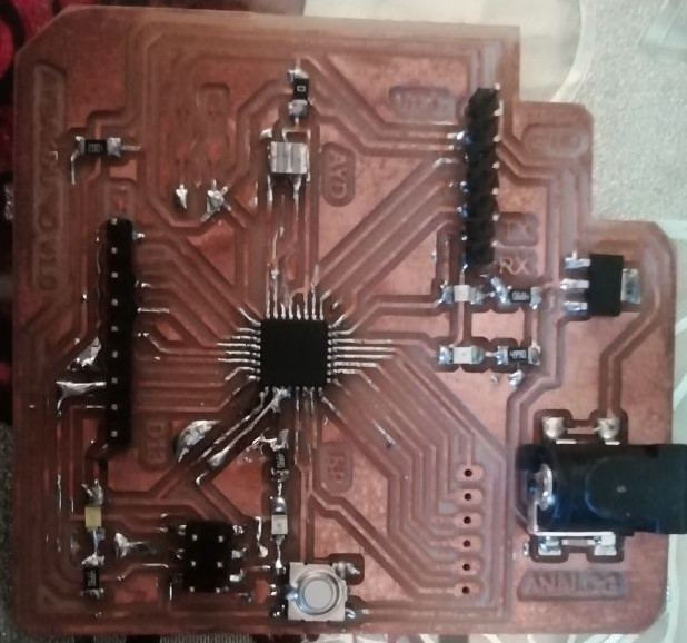
this week i have designed a new board which is based on atmega328p chip and I named this board Aybakduino V1.0
this will work as general board so it can be used on so many application (input, output, communication )
Note :to learn how to design the board using EAGLE software check out the Electronics Design week
as you see on the schematic down below there is:
- analog input pins
- PWM output pins
- digital input pins
- digital output pins
- serial communication pins
- SPI communication pins


Board layout

check the Electronics Production week to know how to fabricate the PCB and how to deal with (MODS and RML files ) step by step

for this week assignment i will use ultrasonic sensor which is a distance sensor.
The ultrasonic sensor sends ultrasonic bursts and mesures the time difference of the signal comming back
this is the pinout for the HC-04 ultrasonic sensor .
| Aybakduino | HC-04 ultrasonic sensor |
|---|---|
| VCC | VCC |
| GND | GND |
| D5 | Echo |
| D6 | Trig |

how to calculate distance?

distance = speed*time
The speed of sound waves is 343 m/s.
total distance =343*Time/2
Total distance is divided by 2 because signal travels from HC-SR04 to object and returns to the module HC-SR-04.
Code
to upload this code to the controller board you can follow this way from Embedded Programming week.
#define echoPin 5
#define trigPin 6

long duration;
int distance;

void setup() {
  pinMode(trigPin, OUTPUT);
  pinMode(echoPin, INPUT);
  Serial.begin(9600);
  Serial.println("Ultrasonic Sensor HC-SR04 data input week");
  Serial.println("using aybakduino V1.0");
  delay(2000);
}
void loop() {

  digitalWrite(trigPin, LOW);
  delayMicroseconds(2);
  digitalWrite(trigPin, HIGH);
  delayMicroseconds(10);
  digitalWrite(trigPin, LOW);
  duration = pulseIn(echoPin, HIGH);
  distance = duration * 0.034 / 2;
  Serial.print("Distance: ");
  Serial.print(distance);
  Serial.println(" cm");
}
to read the ultrasonic sensor data via serial monitor you can connect Arduino with FTDI cable with following pinout
| Aybakduino | FTDI cable |
|---|---|
| VCC | VCC |
| GND | GND |
| TX | RX |
| RX | TX |