Embedded Programming

Group assignment
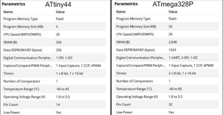
We will compared two AVR families in this section: ATtiny44 from the tinyAVR family and ATmega328P from the megaAVR family.
Feature Comparison
in the table below there is a comparison between two of the most commonly used MCUs and the comparison is about (program memory type, program memory size, CPU speed, GPIOs count, etc...) and you can choose between these two MCUs based on the application that you want to use on
Programming using avr-dude
"avrdude is a program that is used to update or read the flash and EEPROM memories of Atmel AVR microcontrollers on FreeBSD Unix. It supports the Atmel serial programming protocol using the PC's parallel port and can upload either a raw binary file or an Intel Hex format file. It can also be used in an interactive mode to individually update EEPROM cells, fuse bits, and/or lock bits (if their access is supported by the Atmel serial programming protocol.) The main flash instruction memory of the AVR can also be programmed in interactive mode, however this is not very useful because one can only turn bits off. The only way to turn flash bits on is to erase the entire memory (using avrdude's -e option)."
Programming Using Arduino IDE
"Arduino IDE is a special software running on your system that allows you to write sketches (synonym for program in Arduino language) for different Arduino boards. The Arduino programming language is based on a very simple hardware programming language called processing, which is similar to the C language."
C Vs. Arduino C
the main difference between the C language and Arduino C language is that the Arduino C language Is a contest of some prebuilt functions and library and that will make the programming process easier compared to the C language but in terms of execution speed the C language is faster than Arduino C language .
individual assignment
this week I program my board that I already make it in electronics design week . first of all, I read the datasheet then programed the board using the programer that I had made in electronics production week , in the programming process, I used Arduino IDE and the avrdude.
let's take a look at the attiny44 data sheet
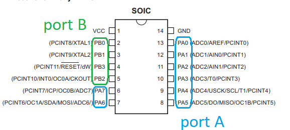
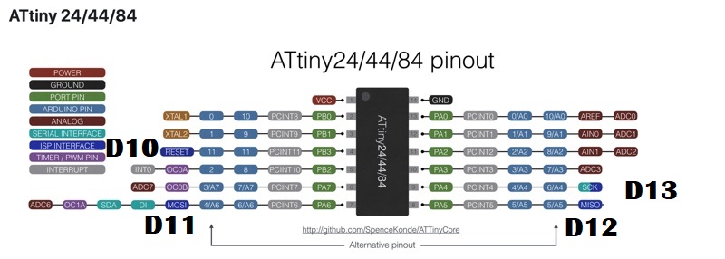
attiny44 Pin Configurations
It is important to know that Attiny44 has 2 ports, port A has 8 pins and port B has 4 which means that we have 12GPIO (General Purpose Input Output) pins.
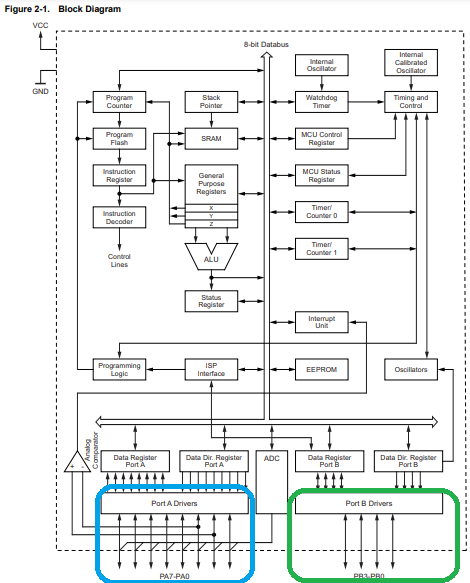
when we look at the block diagram down below we will see that port B and port A were connected to data registers before the data bus which will specify ports purpose based on the program that you upload it.
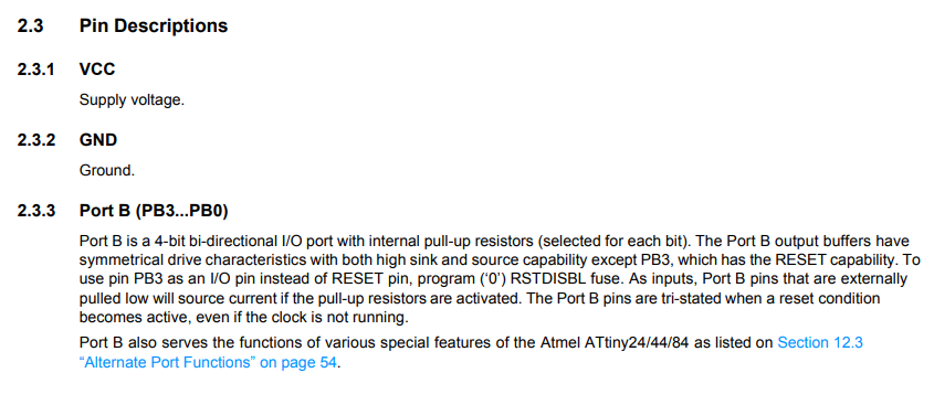
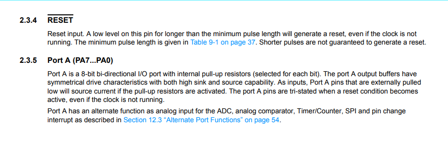
here are the Pin Description quoted from the datasheet .
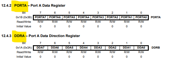
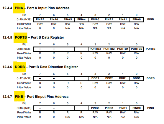
Digital I/O Ports Registers
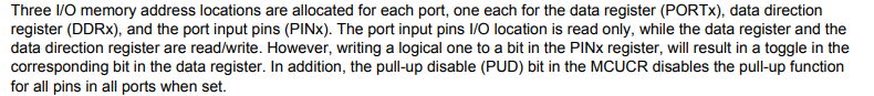
Each port pin consists of three register bits: DDxn, PORTxn, and PINxn. As shown down below, the DDxn bits are accessed at the DDRx I/O address, the PORTxn bits at the PORTx I/O address, and the PINxn bits at the PINx I/O address. The DDxn bit in the DDRx Register selects the direction of this pin. If DDxn is written logic one, Pxn is configured as an output pin. If DDxn is written logic zero, Pxn is configured as an input pin. If PORTxn is written logic one when the pin is configured as an input pin, the pull-up resistor is activated. To switch the pull-up resistor off, PORTxn has to be written logic zero or the pin has to be configured as an output pin. The port pins are tri-stated when reset condition becomes active, even if no clocks are running. If PORTxn is written logic one when the pin is configured as an output pin, the port pin is driven high (one). If PORTxn is written logic zero when the pin is configured as an output pin, the port pin is driven low (zero).
Arduino IDE with Fab ISP
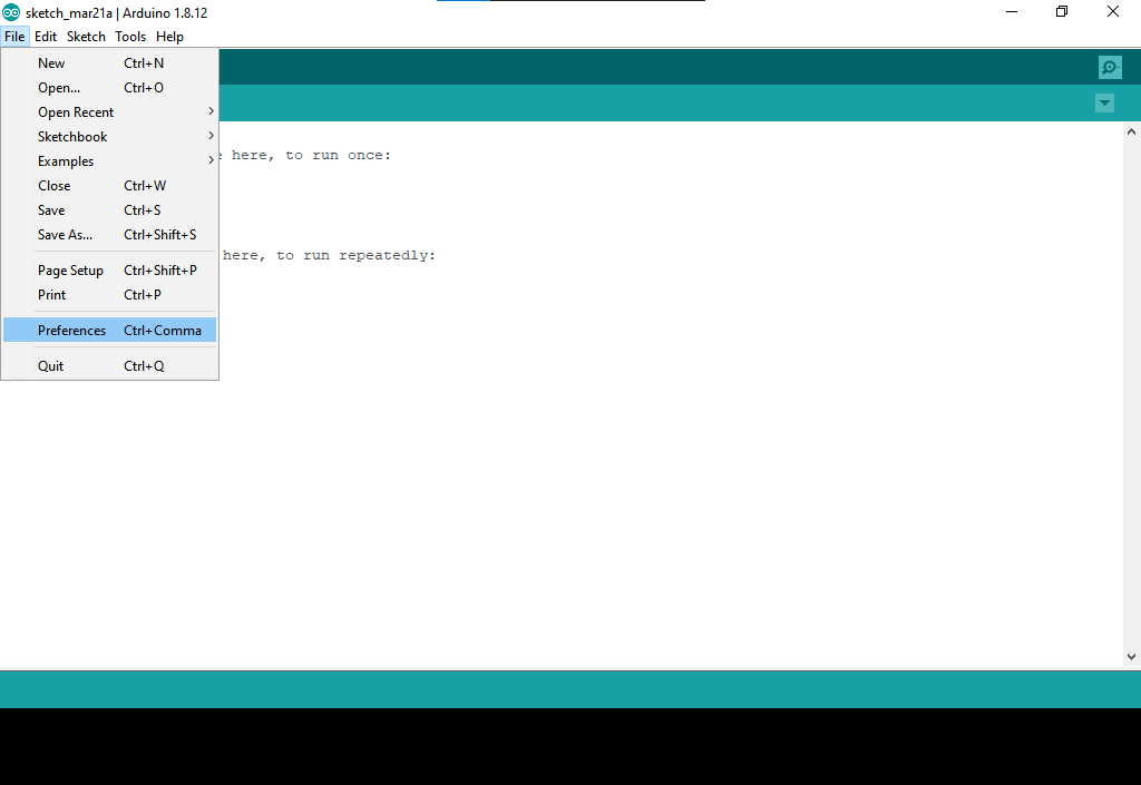
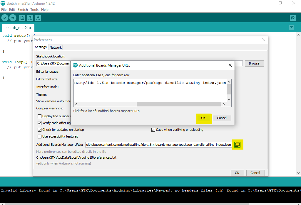
to program my board I use Arduino IDE which is an integrated development environment that is fully computable with Arduino boards but if you want to program another microcontroller you have to do some steps before beginning. the first step is to install the microcontroller, in our case the microcontroller is attiny44, to do so go to file>>preferences>> then pest the below link to additional board manager URLs then click on the yellow-colored icon then press ok
https://raw.githubusercontent.com/damellis/attiny/ide-1.6.x-boards-manager/package_damellis_attiny_index.json
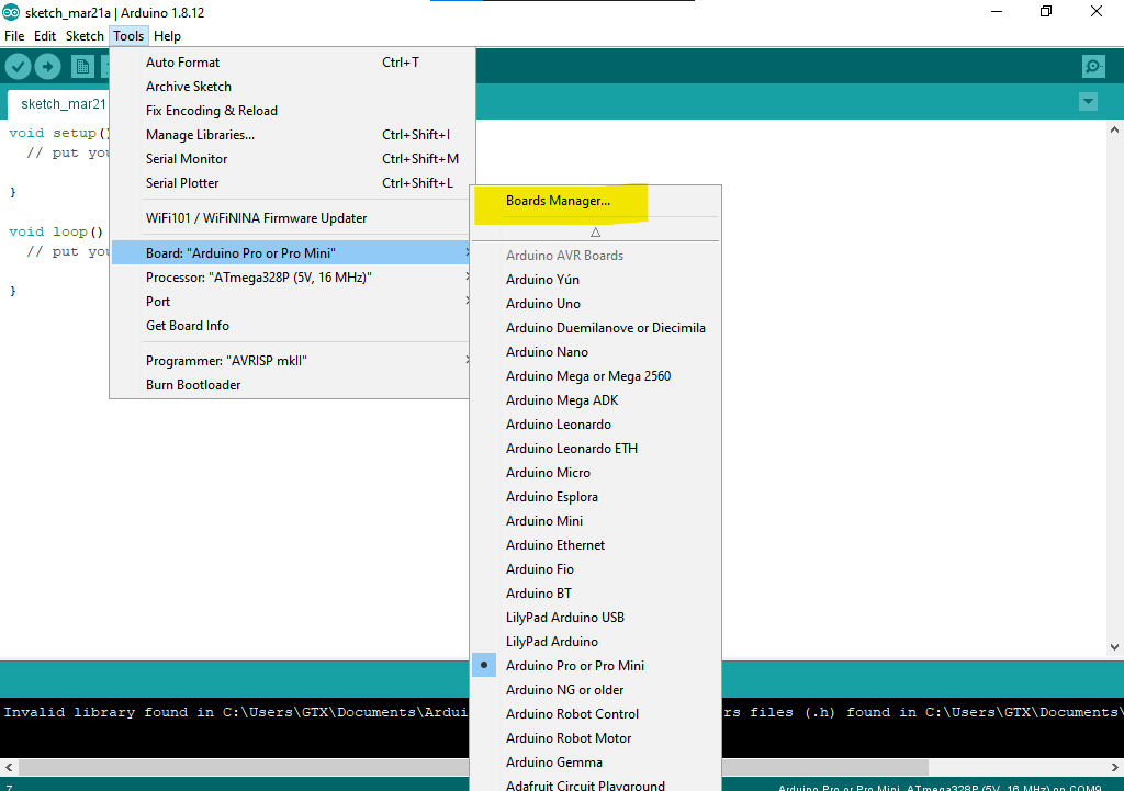
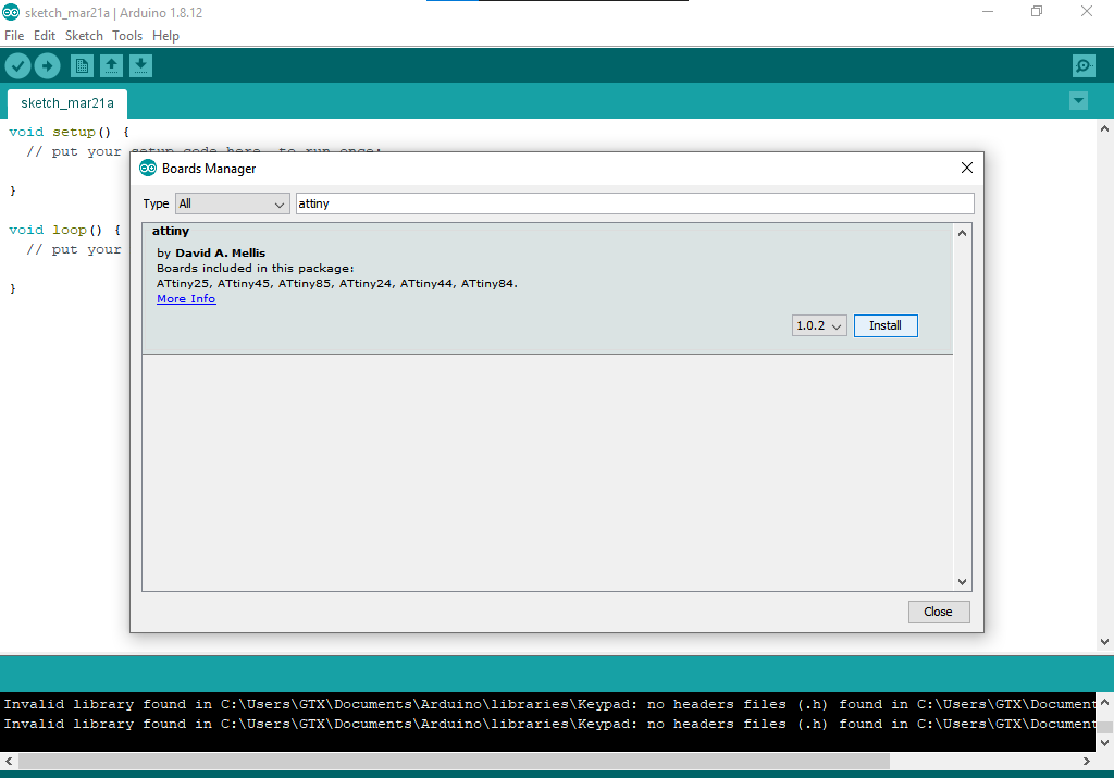
now go to tools>>board>>boards manager, search for attiny then click install.
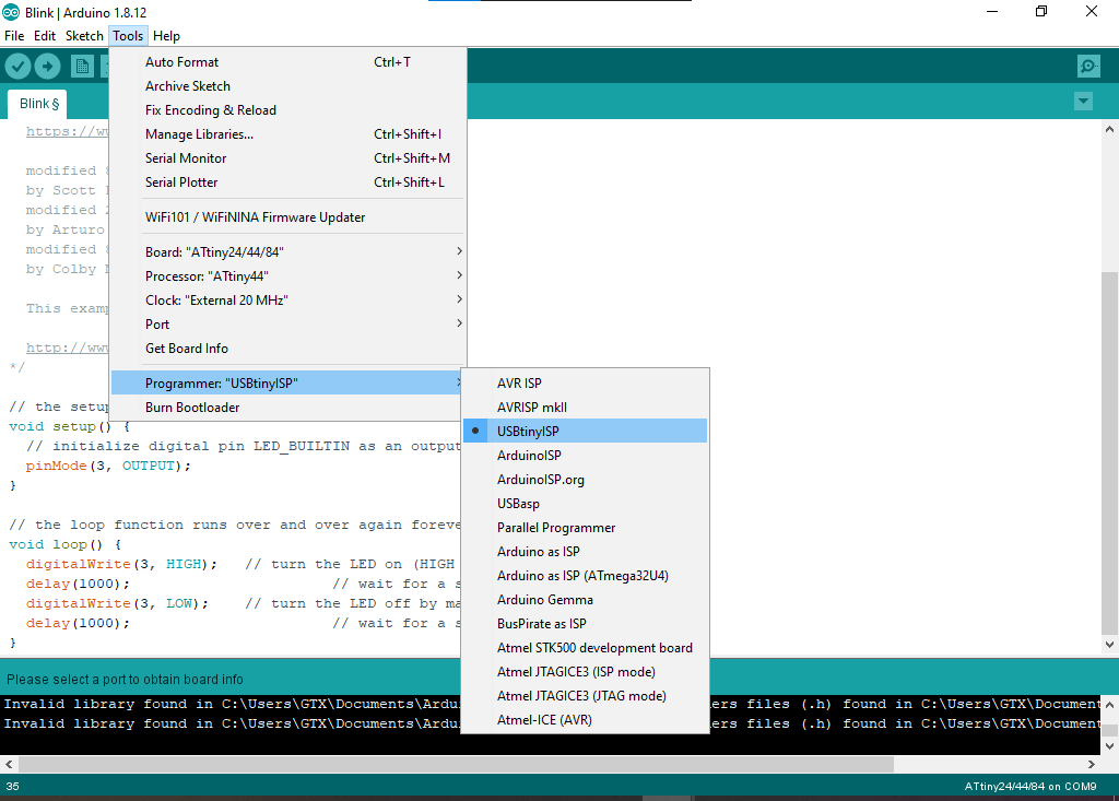
now let's upload simple code to make sure that the setup is working, first, we have to select USBtinyISP as a programer .
so let's take a look at the code, here I will upload the blink example just for testing but I edit the sketch and add my LED pin number as shown in the figure is pin number 3 when you are programming using Arduino IDE which is port A pin3
void setup() {
  // initialize digital pin LED_BUILTIN as an output.
  pinMode(3, OUTPUT);
}

// the loop function runs over and over again forever
void loop() {
  digitalWrite(3, HIGH);   // turn the LED on (HIGH is the voltage level)
  delay(1000);                       // wait for a second
  digitalWrite(3, LOW);    // turn the LED off by making the voltage LOW
  delay(1000);                       // wait for a second
}
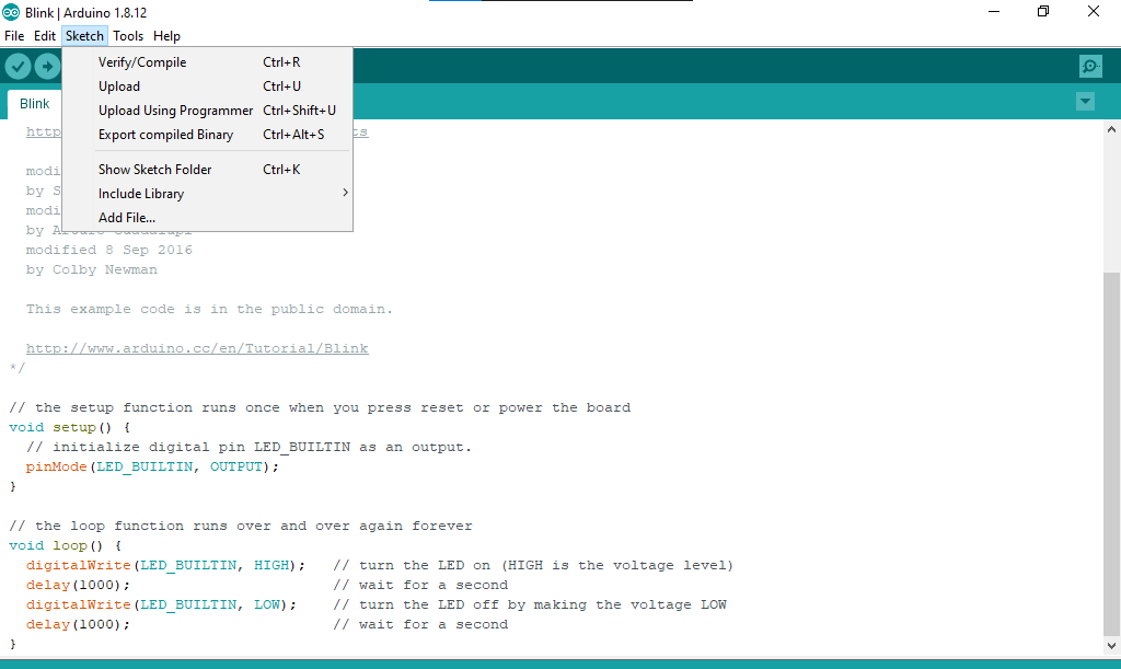
now let's upload the code using usptiny, so go to sketch>> upload using programmer .
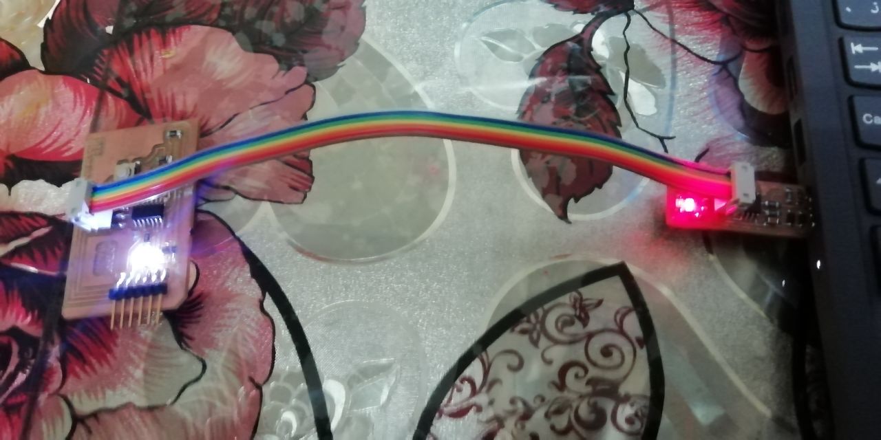
and it works
now let's write a new code, this time we will use a push button and the strategy is when pressing the button the LED start flashing with a 50ms delay.
#define LED 3
#define button 2
void setup() {
  // put your setup code here, to run once:
 pinMode(LED, OUTPUT);
}
void loop() {
  // put your main code here, to run repeatedly:
 if(digitalRead(button)==LOW){
  digitalWrite(LED,HIGH);
  delay(50);
    digitalWrite(LED,LOW);
    delay(50);

 }
 else{
    digitalWrite(LED,LOW);

 }
}
avrdude with Fab ISP
The makefile
Makefile defines some settings and commands used to program the microcontroller in our case (ATtiny44). The Makefile code below stores ceramic resonator speed in our case (20MHZ), project name, programmer, target board, lfuse value which can be calculated using a fuses calculator and two commands used to program ifuse (program-avr-fuses) value and upload hex file (program-avr).