Electronics Design
Group assignment
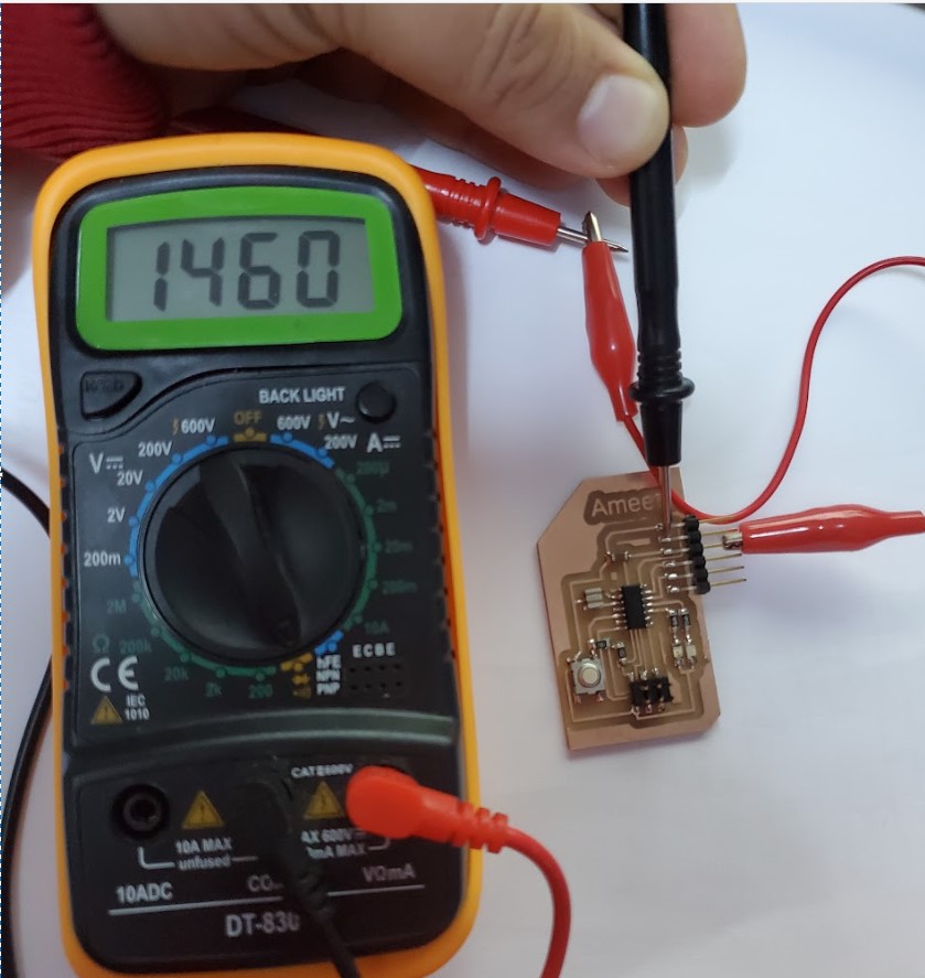
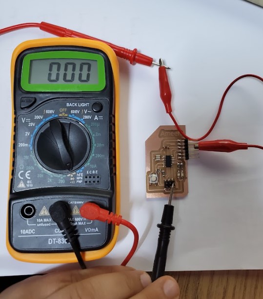
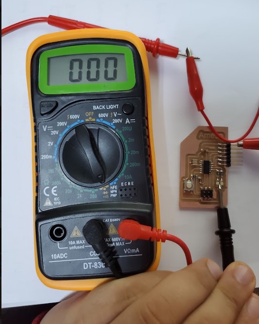
in this part of the assignment, we test the trace's connectivity of the Amin Yousef board using the digital multimeter.
VCC-GND
here we check the connectivity between VCC and GND and to do so we buy the digital multimeter in connectivity mode (it should make a sound like beeeeep when you select this mode) then we butt the poles on VCC and GND it should not make any sound and the number that appear on the screen represent the resistance between VCC and GND inside the controller which is a good indicator that tells us that the controller works probably , other if the multimeter make any sound that means that there is a short ciruct between VCC and GND
after that we check the VCC to VCC connectivity and GND to GND connectivity and the communication pins connectivity
GND to GND connectivity
VCC to VCC connectivity
Individual Assignments
Design Echo Hello Board
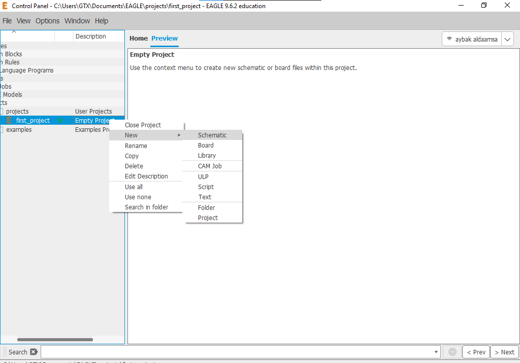
this week we have an assignment to design, mill a PCB, and upload a code into it so I decide to use EAGLE software to design the board . the design is a two-step process first you have to draw the schematic and arrange the terraces then you have to layout your PCB. so let's learn how to design PCBs and how to deal with EAGLE software the first step is to make a new project that will contain the schematic and board layout to start a new project right click on "projects" then a new project
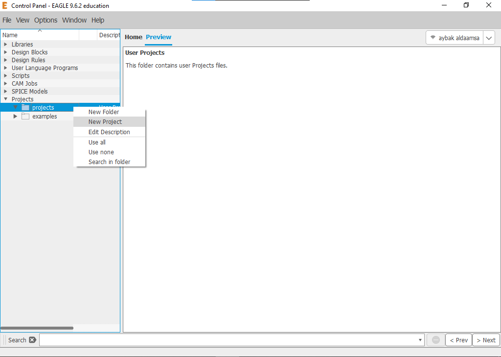
after making a new project and naming it as in my case "first_project" let's start our first schematic. right-click on the project that we make it then new>> schematic
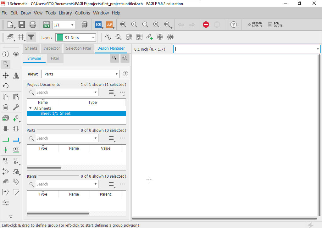
this screen will appear
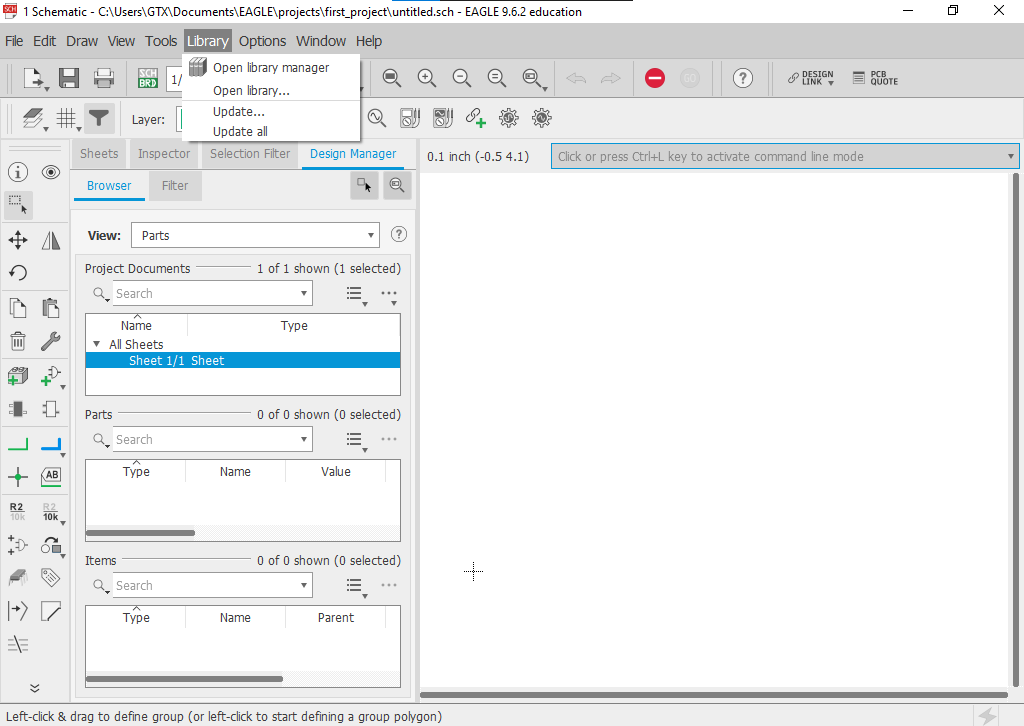
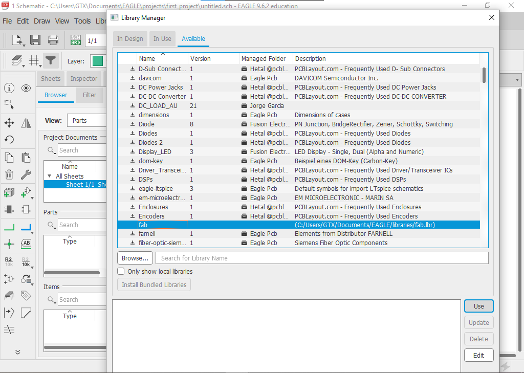
now it's important to import fab labs library to make the design with the right footprint dimensions.
you can install the component library from here then you have to move the library to “..\Documents\EAGLE\libraries”.
now from Library then Open library manager.
then select “Available” tab Click on “Browse” and locate fab.lbr on your drive. Click “Open”. This will add fab.lbr to “Available” libraries list.
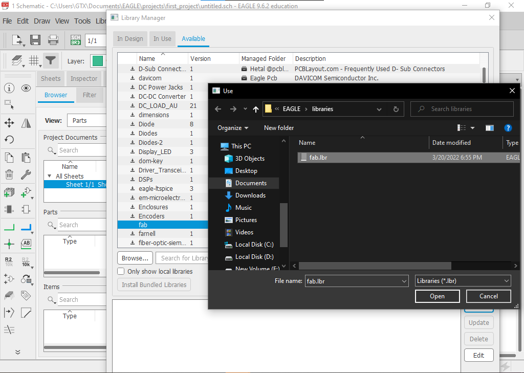
now you can make it usable by selecting the library then clicking use.
Schematic
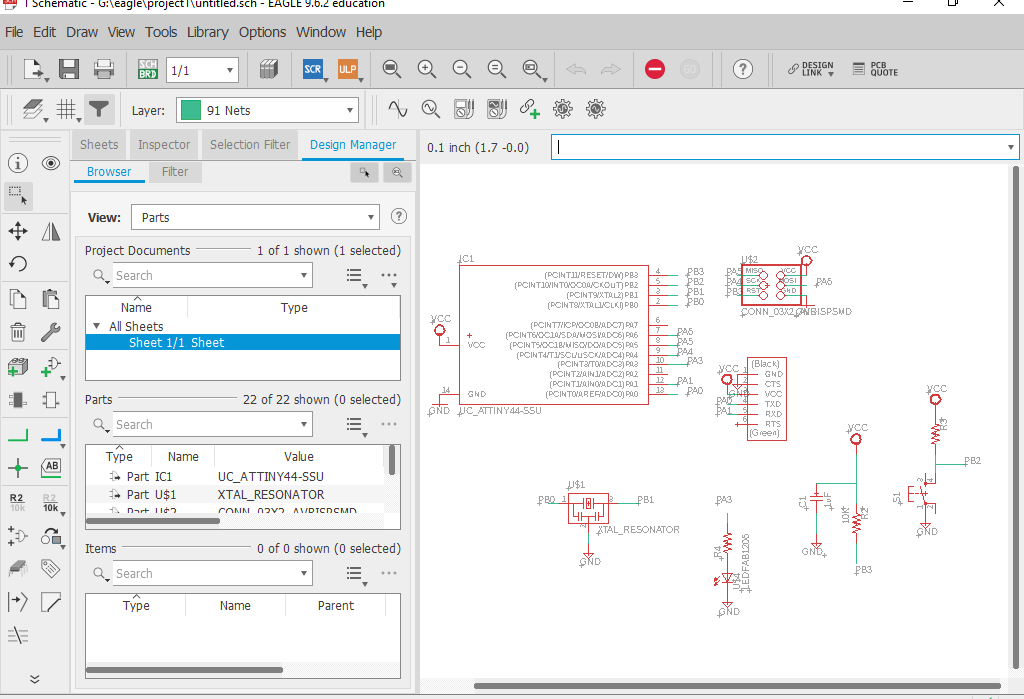
after including the library lets import the component that we will need to redraw the schematic for this circuit and add a push button with LED
| component | Lib Name | Qty |
|---|---|---|
| ATtiny44 | UC_ATTINY44-SSU | 1 |
| Crystal 20MHz | XTAL_RESONATOR | 1 |
| Header 3x2 ISP | CONN_03X2_AVRISPSMD | 1 |
| Header 1x6 FTDI | CONN_06_FTDI-SMD-HEADER | 1 |
| Capacitor unpolarized 1uF | CAP_UNPOLARIZEDFAB | 1 |
| Resistor 10kOhm | R1206FAB | 3 |
| Push button | SW_SWITCH_TACTILE_6MM6MM_SWITCH | 1 |
| LED | LEDFAB1206 | 1 |
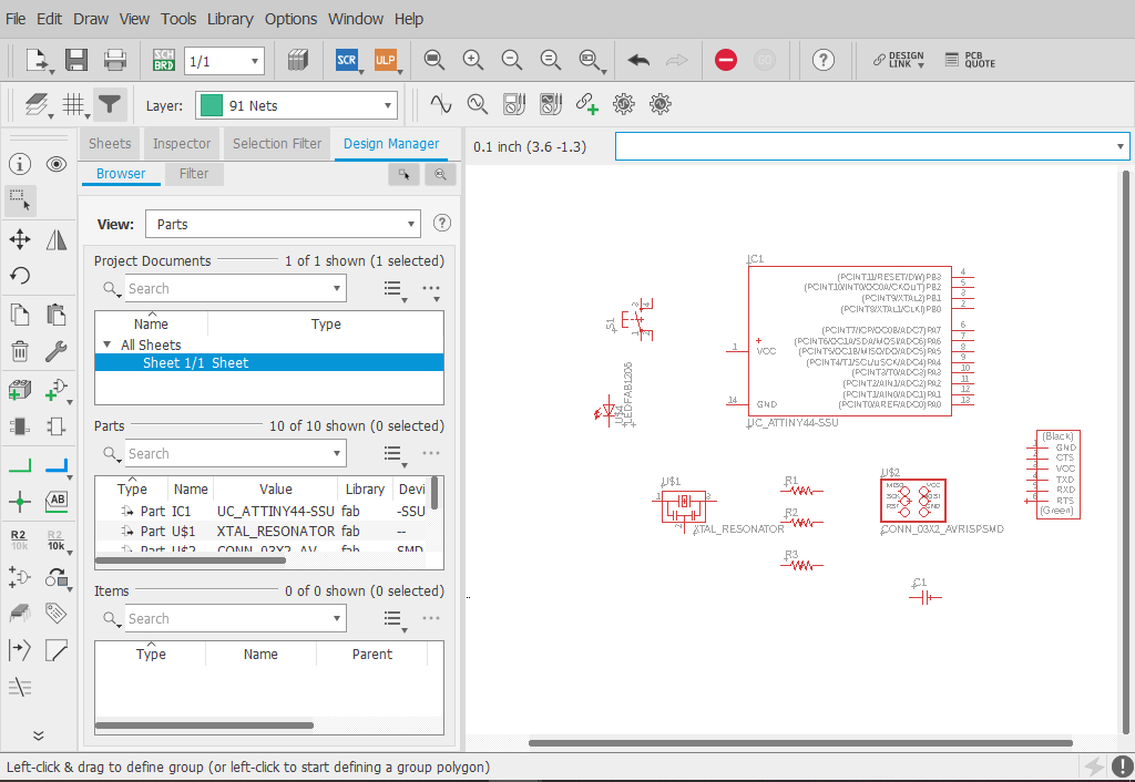
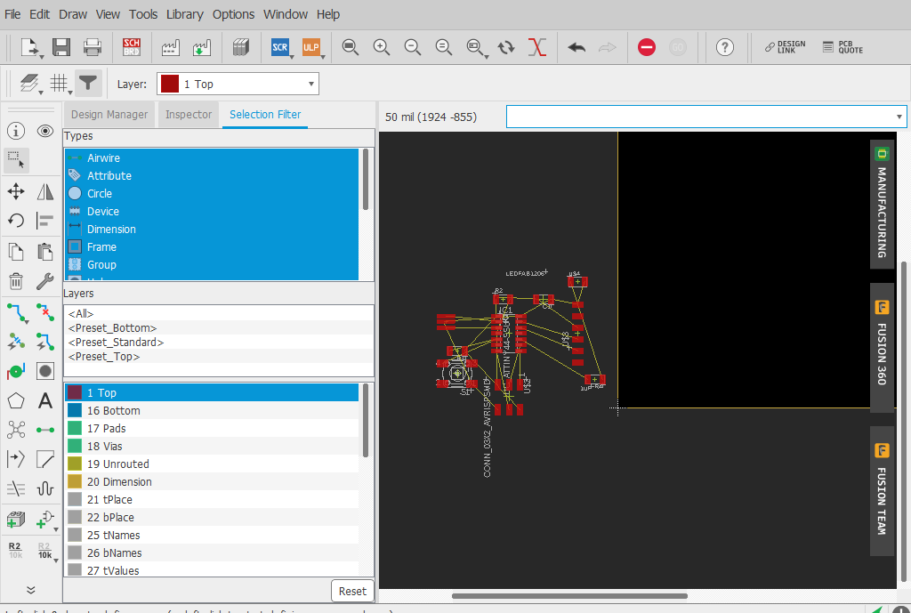
now after adding all the components that we need lets to connect it using the "NAME " tool **  ** to keep the schematic clear and understandable
after drawing the schematic let's generate the board to make the traces by pressing " generate/switch to board " **  ** that's will make this screen down below appears
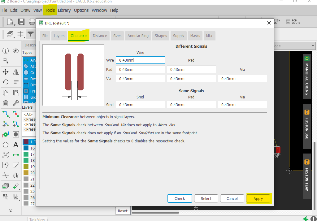
before starting making the traces, we have to define clearance parameters Based on the traces milling tool that we will use later to mill the PCB.
so go to tools DRC **  ** clearance tap then define your parameters in my case I'm using 1/64” (0.4 mm) milling bit so I define all my signals to 0.43mm and the increase
0.03mm was a safety offset
** clearance tap then define your parameters in my case I'm using 1/64” (0.4 mm) milling bit so I define all my signals to 0.43mm and the increase
0.03mm was a safety offset
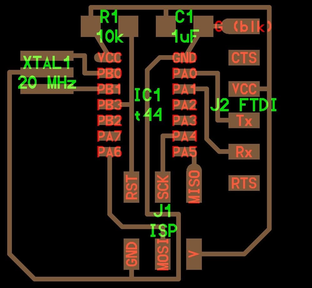
so now we can start routing using the Route Airwire tool **  ** of course you can change the position and orientation of the components to find the easiest way to make the PCB without making a mess. an additional point to make your PCB special is to write some things on it like your name or a special sentence that represent you using text tool
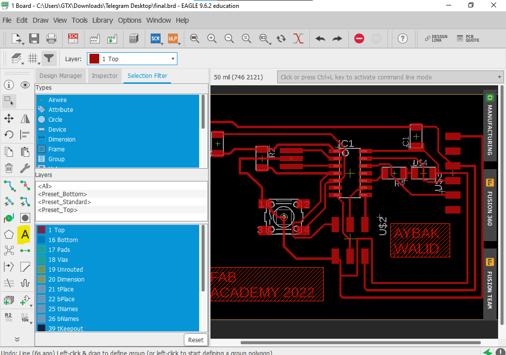
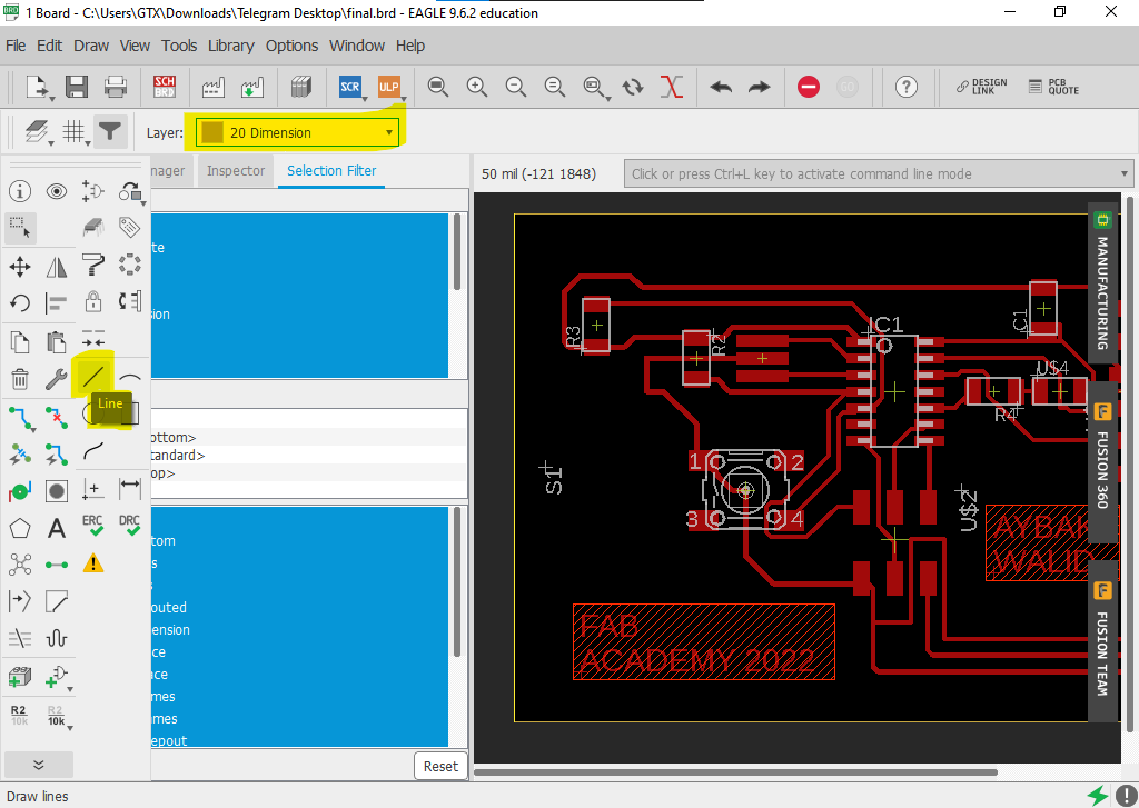
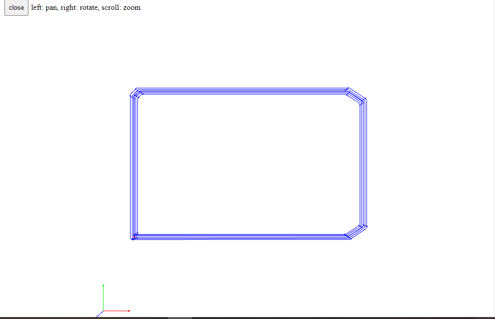
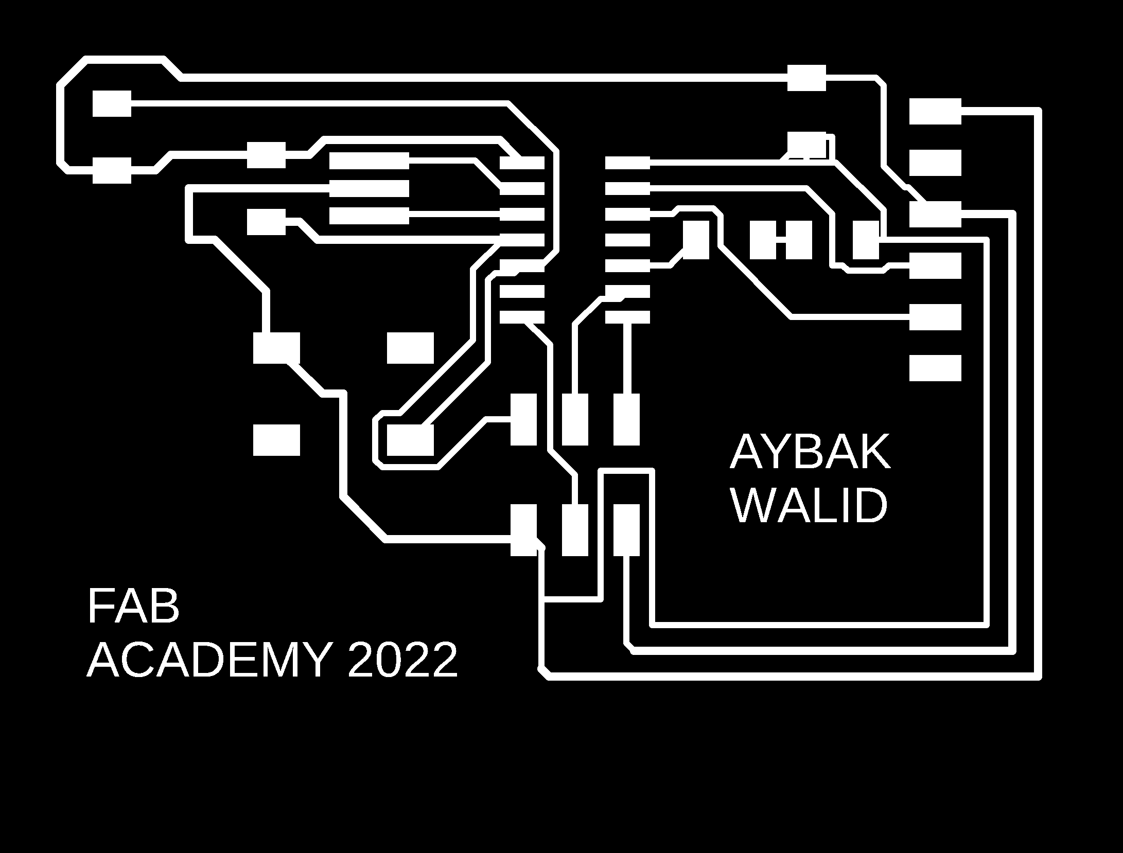
the next step is to draw the PCB layout. first of all, you have to select the "dimension" layer instead of the "top" layer or any layer else. now you can select the shape that you want to draw personally I use simple lines and some curves put you can use more complex shapes to draw the layout.
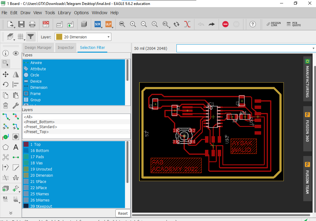
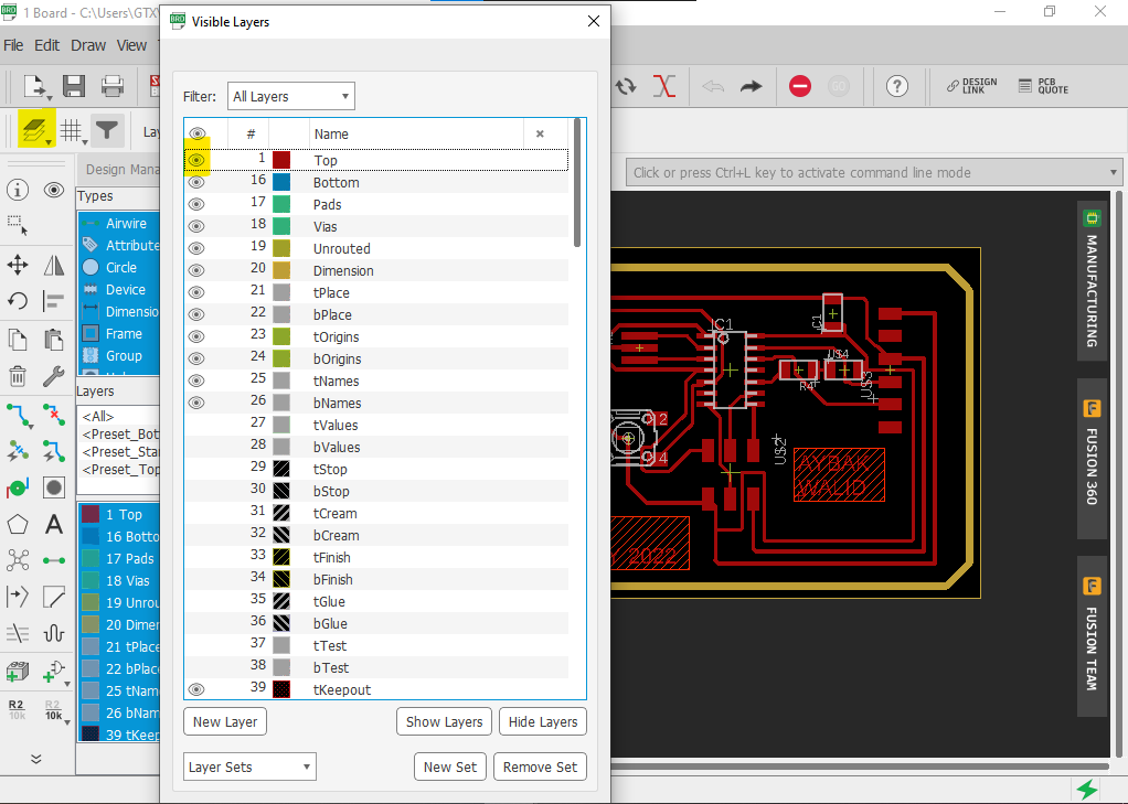
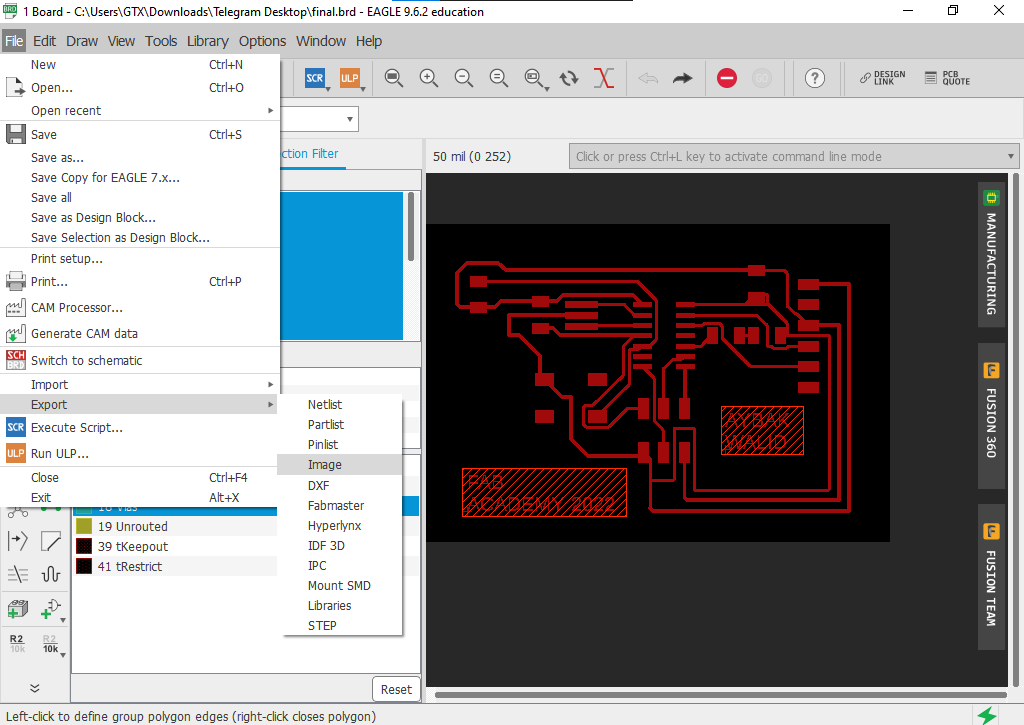
its time to export our design . we will export the traces and layout separately because each one has a different milling tool . so let's start with traces, to export only the traces hide all layers except the top layer, by clicking on the layer then on eye icon to hide the layers
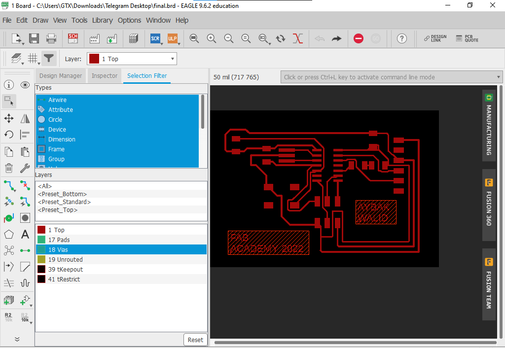
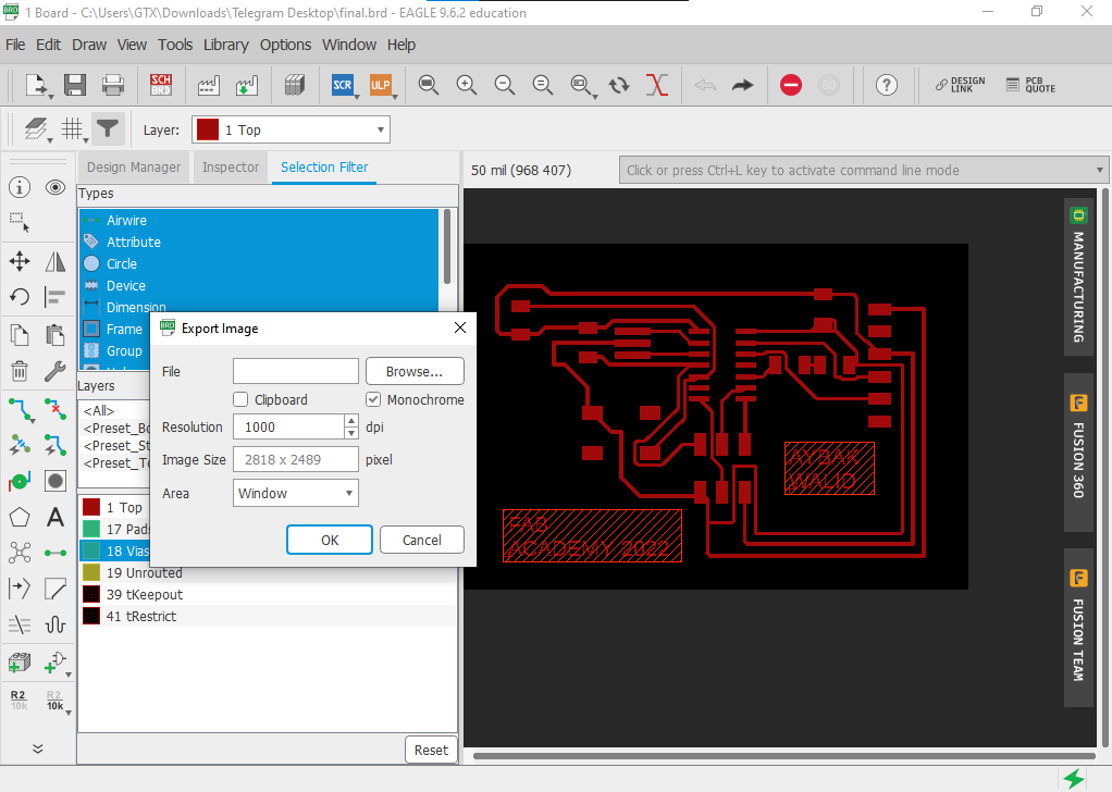
go to file>>export>>image then chose a prober resolution and check the monochrome box to have a two-color image
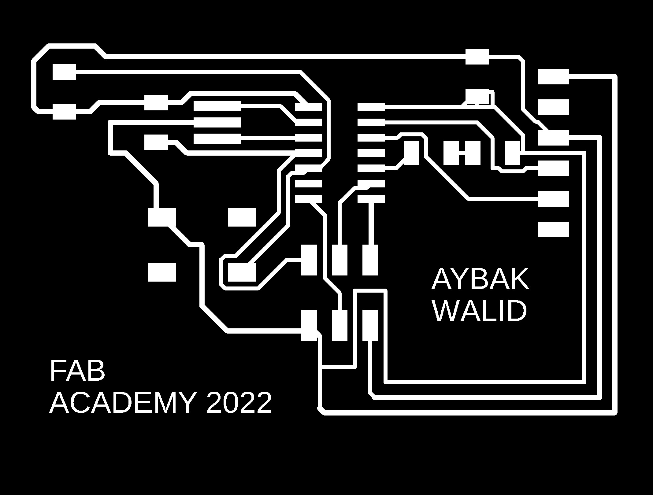
and this will be the result
by applying the same steps on the outline we will get

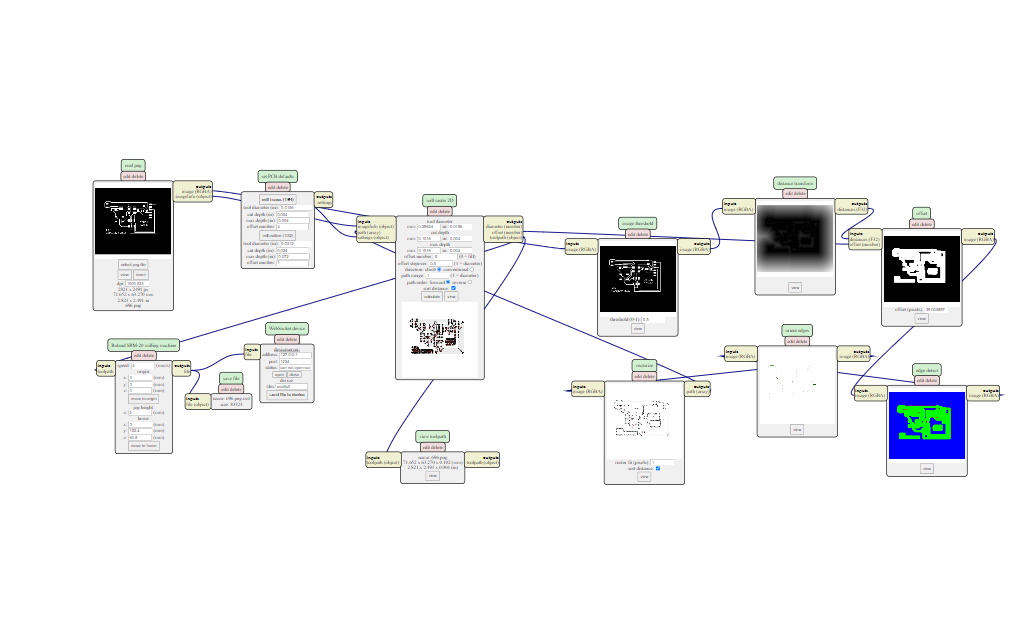
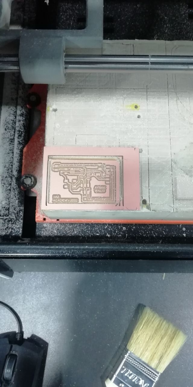
MODS
before cutting we have to make the tool path using MODS so I use the following settings to mill the traces and the outline
| description | Tool Diameter | Cut Depth | Max Depth | Offset Number | Speed | Origin |
|---|---|---|---|---|---|---|
| Mill Traces (1/64) | mm: 0.39624 / in: 0.0156 | mm: 0.1016 / in: 0.004 | mm: 0.1016 / in: 0.004 | 5 | 4 mm/s | x = 0 mm, y = 0 mm, z = 0 mm |
| Mill Outline (1/32) | mm: 0.79248 / in: 0.0312 | mm: 0.6096 / in: 0.024 | mm: 1.8287999999999998 / in: 0.072 | 1 | 4 mm/s | x = 0 mm, y = 0 mm, z = 0 mms |
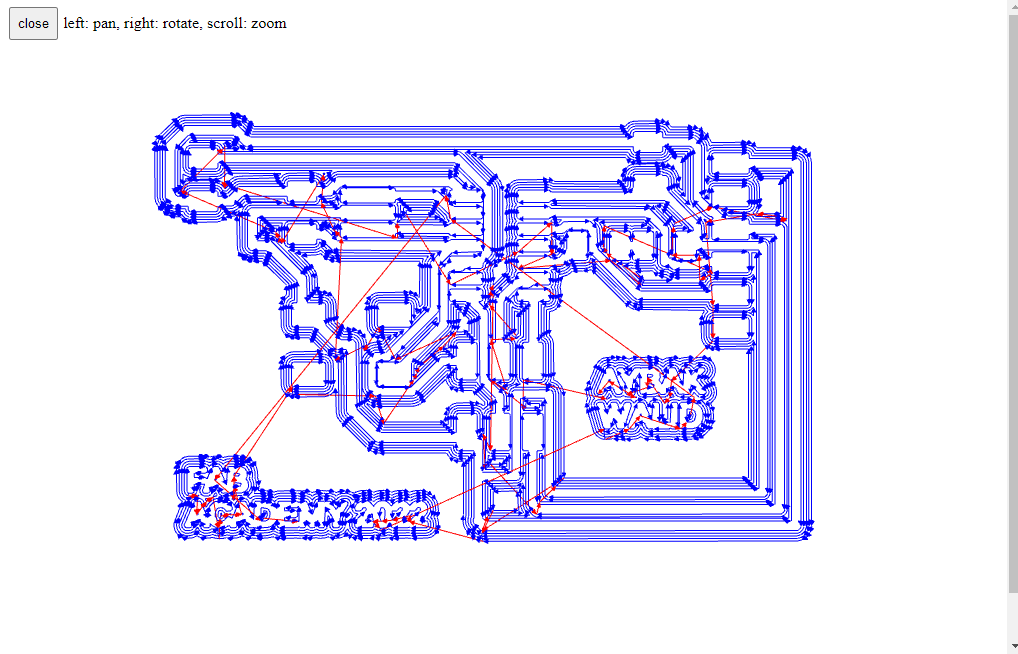
after applying the values in the table these was the results.
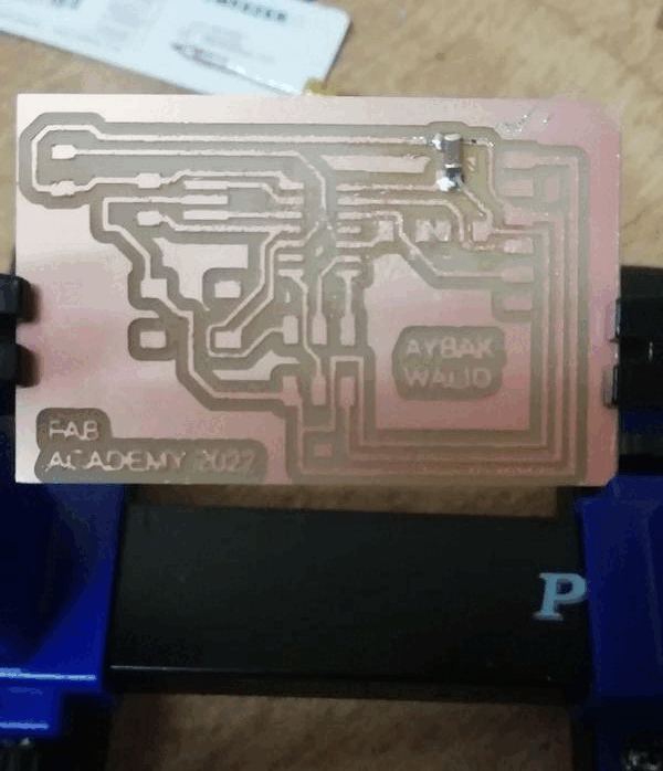
Soldering
Programming
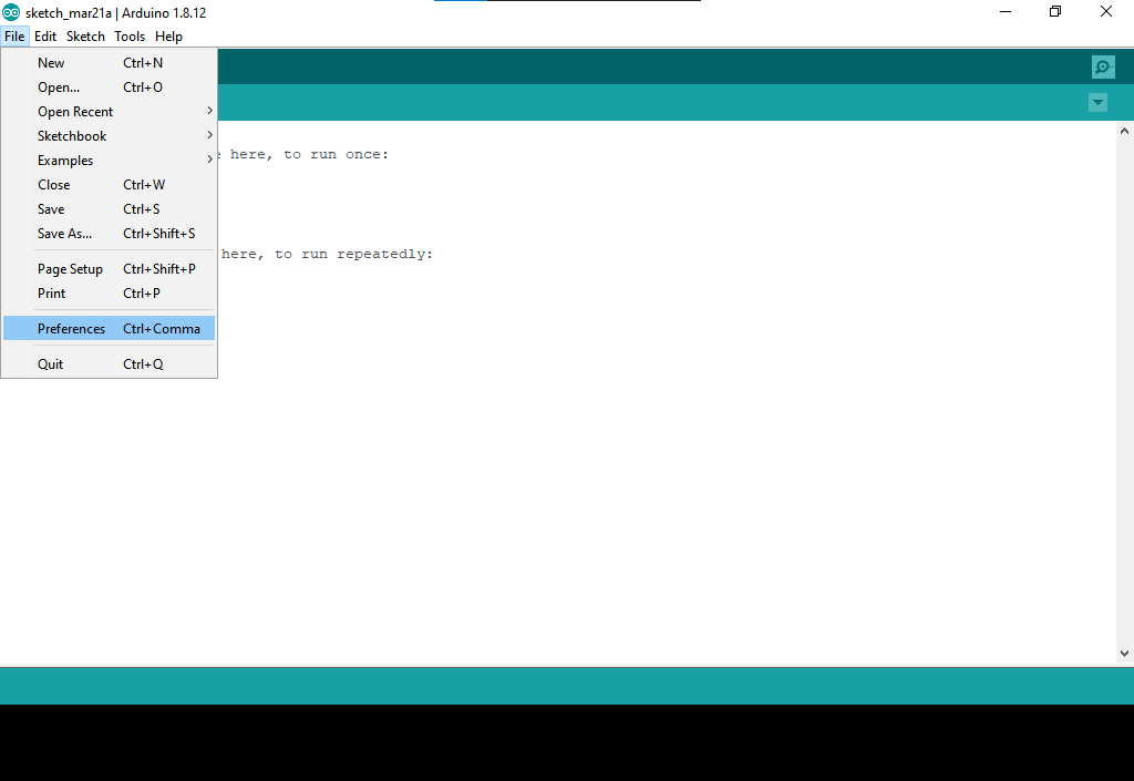
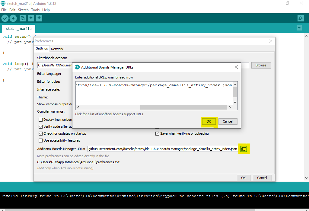
to program my board I use Arduino IDE which is an integrated development environment that is fully computable with Arduino boards but if you want to program another microcontroller you have to do some steps before beginning. the first step is to install the microcontroller, in our case the microcontroller is attiny44, to do so go to file>>preferences>> then pest the below link to additional board manager URLs then click on the yellow-colored icon then press ok
https://raw.githubusercontent.com/damellis/attiny/ide-1.6.x-boards-manager/package_damellis_attiny_index.json
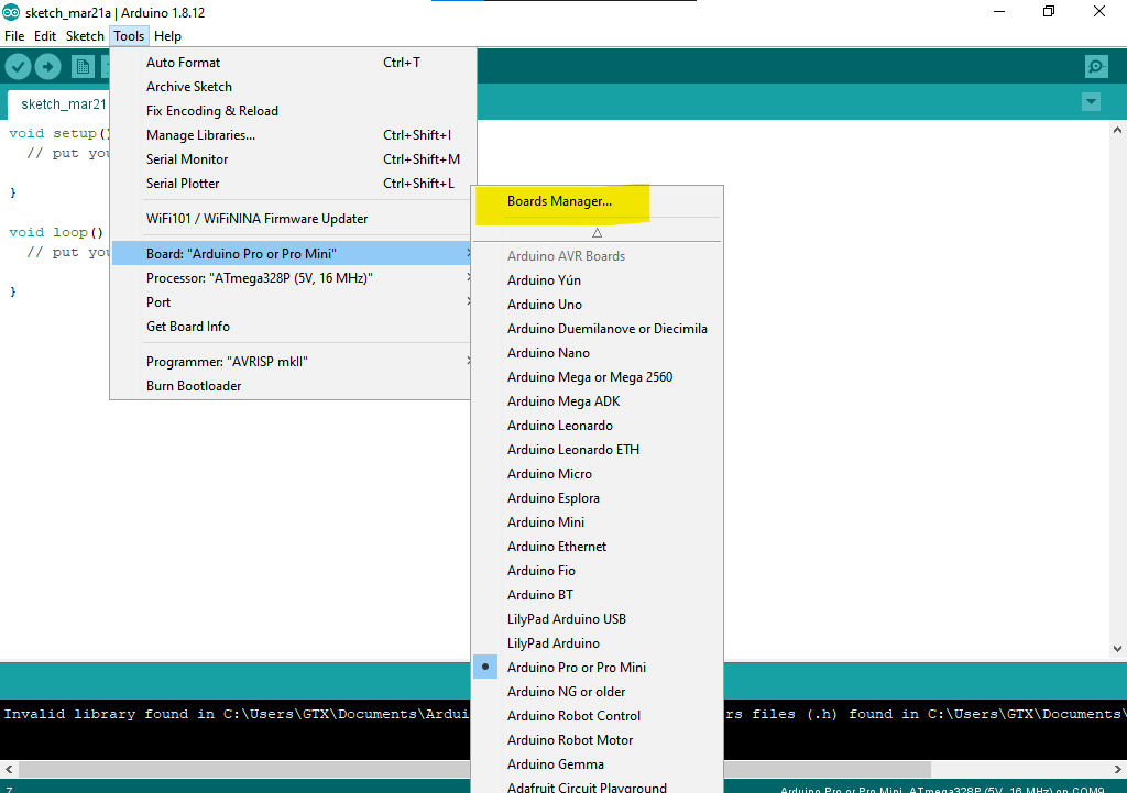
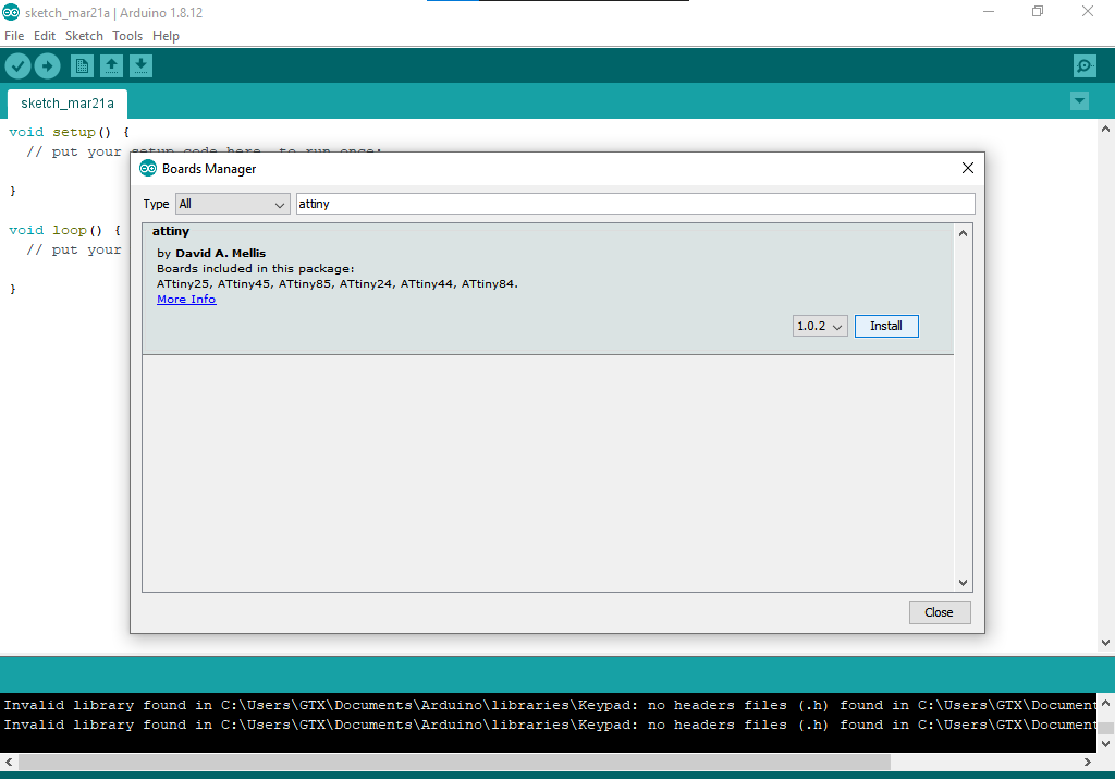
now go to tools>>board>>boards manager, search for attiny then click install.
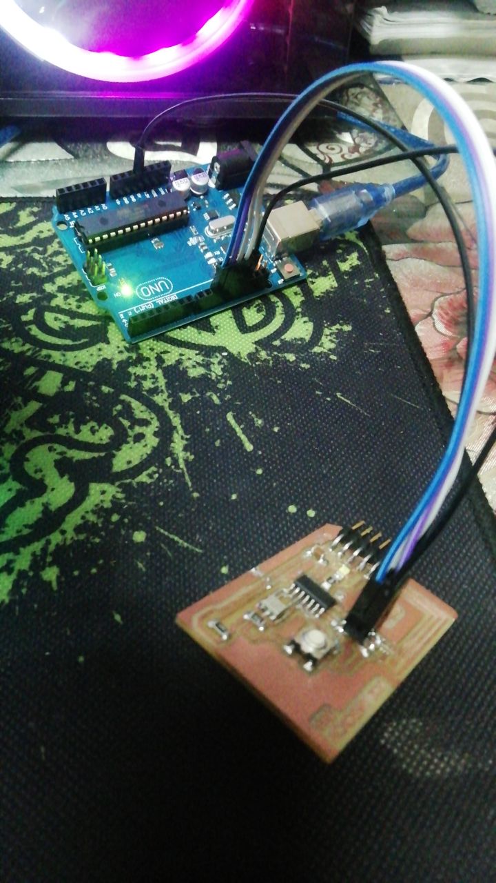
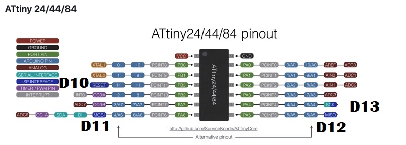
after looking at the Arduino UNO pinout I connect the Arduino UNO to my board as follow:
| Arduin pin | attiny44 |
|---|---|
| 10 | Reset(4) |
| 11 | MOSI (7) |
| 12 | MISO (8) |
| 13 | SCK(9) |
| 5V | VCC |
| GND | GND |
now we are ready to program the board, but we have to define pin numbers in the code so take a look at attiny44 pinout .
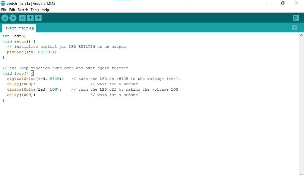
I write a simple blink code based on my design and attiny44 pinout .
	int led=3;
	void setup() {
	  // initialize digital pin LED_BUILTIN as an output.
	  pinMode(led, OUTPUT);
	}

	// the loop function runs over and over again forever
	void loop() {
	  digitalWrite(led, HIGH);   // turn the LED on (HIGH is the voltage level)
	  delay(1000);                       // wait for a second
	  digitalWrite(led, LOW);    // turn the LED off by making the voltage LOW
	  delay(1000);                       // wait for a second
	}
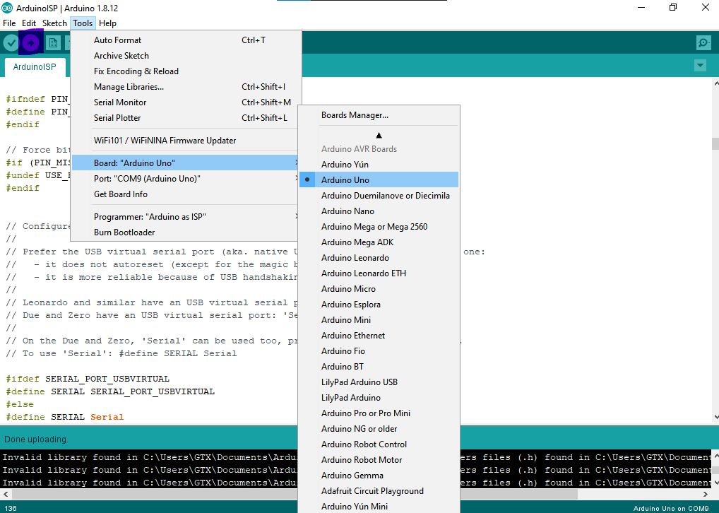
after we write the code its time to upload it . first of all, we have to make Arduino ready to program another microcontroller by uploading the "ArduinoISP" from the examples . make sure that you chose Arduino UNO ( or the Arduino board that you have) then click on the arrow to upload the code
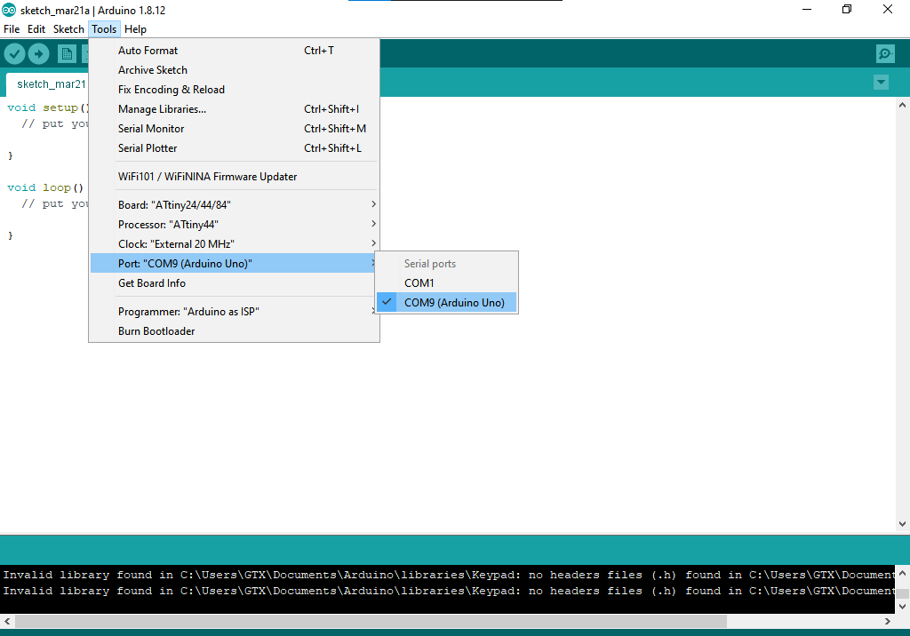
now let's go back to our code to upload it setup connection on Arduino IDE then go to skethc>>upload using programer
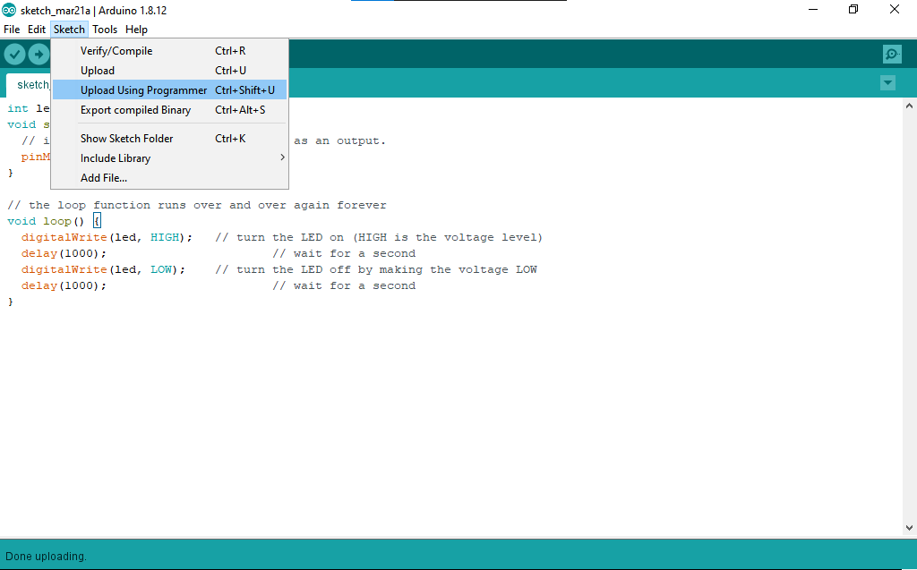
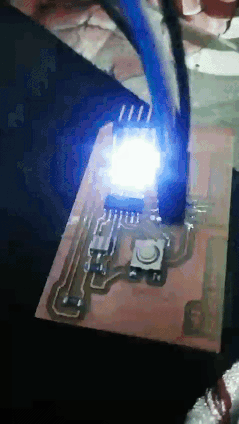
finally!! it works
files to download
Google Drive
direct link