Output Devices

Group Assignments
We measured the power consumption of a DC motor using a DC motor output board.
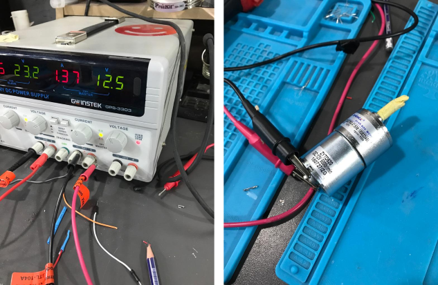
Power (in Watt) is calculated by Power "P" = Voltage "V" x Current "I" Where V is the voltage across the load and I is the current passing through the load. To measure the volatge and current we used Digital Multimeter (DMM)
- Voltage, the Digital Multimeter (DMM) is connected in Parallel with the load.
- Current, the Digital Multimeter (DMM) is connected in Series with the load.
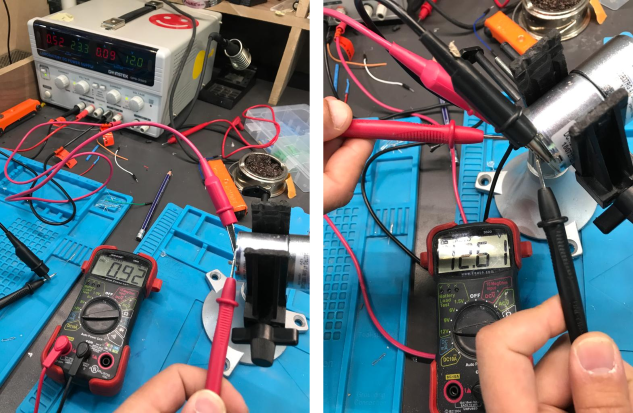
To calculate the power consumption of the DC motor: P = 12.61 x 0.092 P = 1.16 Watt P = 1160 mWatt
individual assignment
this week I make a stepper motor driver and a dc motor driver as an output device also I make a control board using attiny44
let's take a look at working principle for stepper motors Motors convert electrical energy into mechanical energy. A stepper motor converts electrical pulses into specific rotational movements. The movement created by each pulse is precise and repeatable, which is why stepper motors are so effective for positioning applications. here I used unibolar stepper motor particularly jameco 2138812
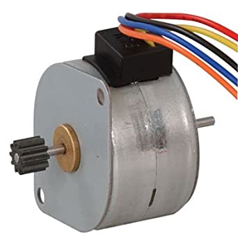
in this motor, there are a five wires yellow black, green, red, and orange each one connected to a separate coil but the orange is connected as common for all coils and I will use it as a VCC .
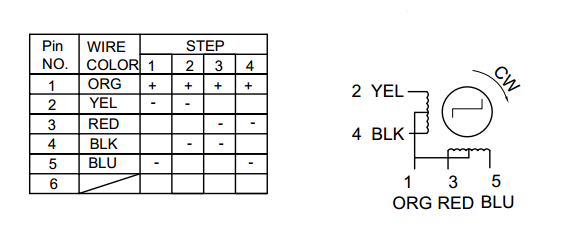
there are many methods to control stepper motors Full Step, Half Step and Micro Step and Wave Drive. i choose the wave drive mode, In this drive method only a single phase is activated at a time. It has the same number of steps as the full step drive, but the motor will have significantly less than rated torque.
you can learn more about control methods here
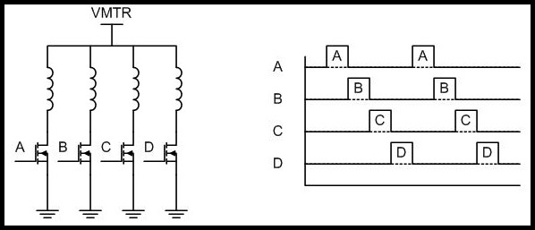
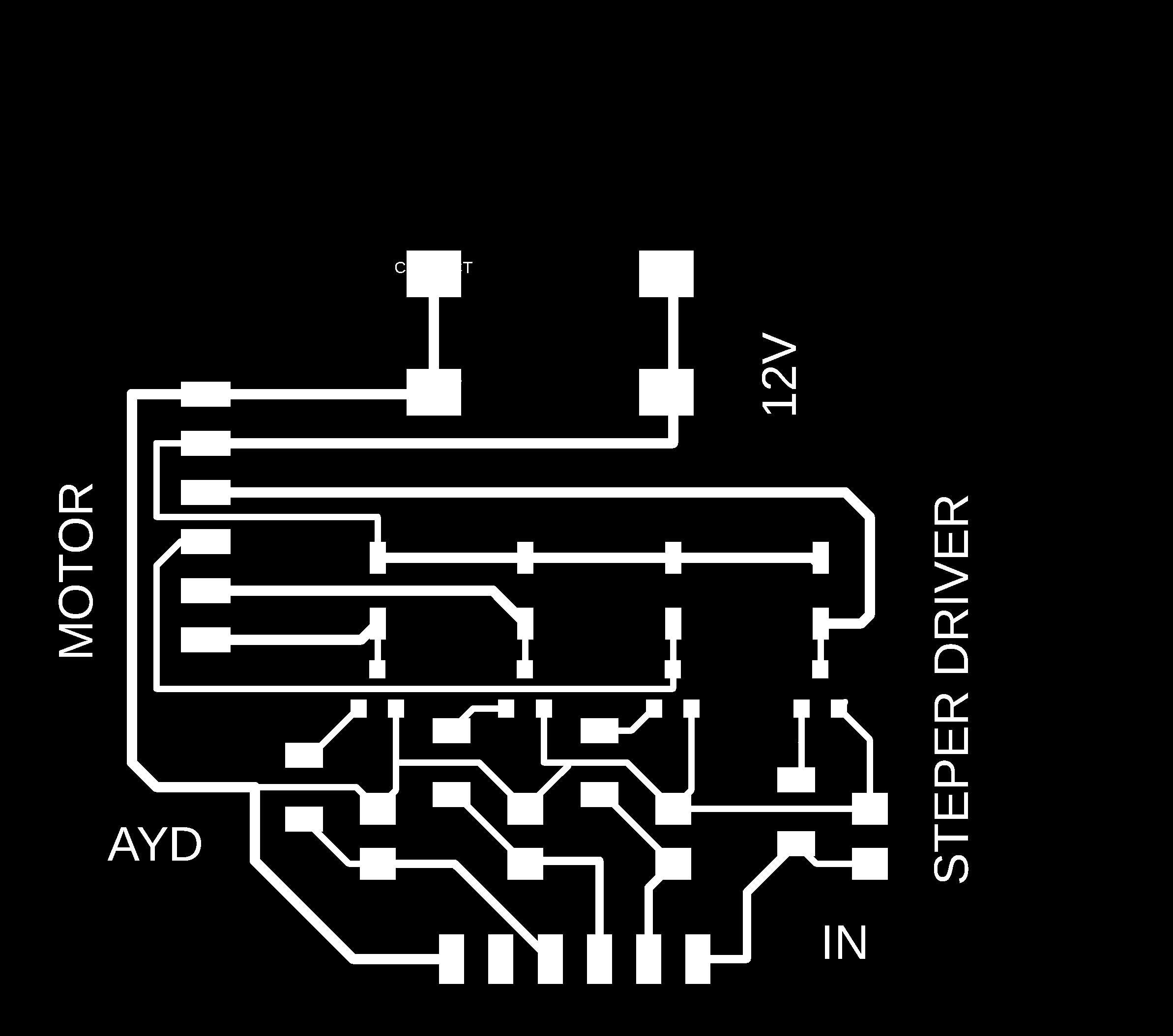
To drive the motor, I used NDS355AN N-Channel MOSFET to control each coil. in the PCB design I connect LED to each MOSFET so when the gate is (coil is energized )the LED will light up as an indicator
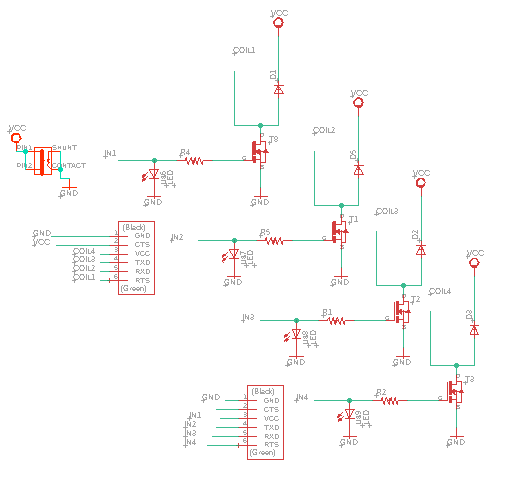
so let's talk more about design. resistor: the resistor is connect the MOSFET gate to the ground so the normal state will be low (bull down resistor ) If there is no resistor the MOSFET will behave oddly. diode: the diode is for protection purpose to protect the MOSFET from damage by the back current ( freewheeling diode)
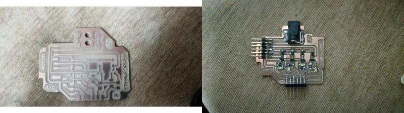
This is the stepper board after welding
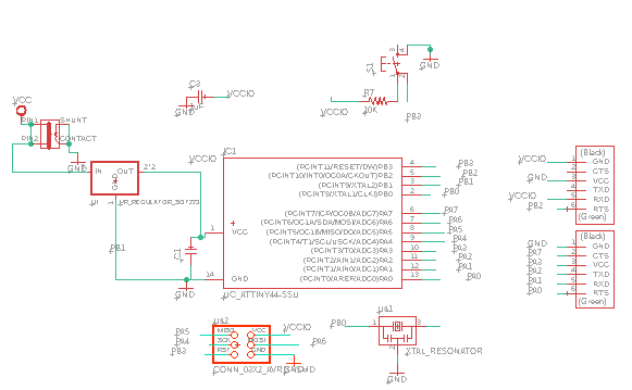
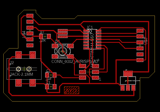
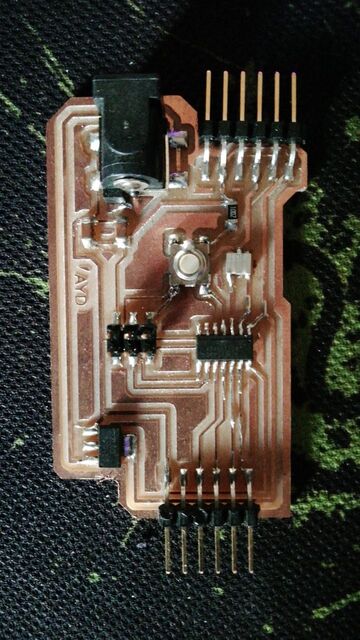
controller board
to control the stepper motor driver I designed a control board that will contain the attiny44 as the main controller, also I add a voltage regulator so you can plug a power source with voltage up to 12V .
To use this control board with other projects I add 6 GPIO including (digital, analog, and PWM pins).
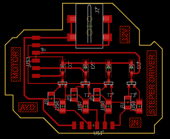
Design and Fabrication
check the Electronics Production week to know how to fabricate the PCB and how to deal with (MODS and RML files ) step by step
to learn how to design the board using EAGLE software check out the Electronics Design week
code
down below you will find the code for controlling the stepper driver .
to upload this code to the controller board you can follow this way from Embedded Programming week.
#define p1 8
#define p2 9
#define p3 10
#define p4 11

void setup() {
  pinMode(p1,OUTPUT);
  pinMode(p2,OUTPUT);
  pinMode(p3,OUTPUT);

  pinMode(p4,OUTPUT);


  // put your setup code here, to run once:

}

void loop() {
  digitalWrite(p1,HIGH);
  digitalWrite(p2,LOW);
  digitalWrite(p3,LOW);
  digitalWrite(p4,LOW);
delay(5);
digitalWrite(p1,LOW);
  digitalWrite(p2,HIGH);
  digitalWrite(p3,LOW);
  digitalWrite(p4,LOW);
delay(5);
digitalWrite(p1,LOW);
  digitalWrite(p2,LOW);
  digitalWrite(p3,HIGH);
  digitalWrite(p4,LOW);
delay(5);
digitalWrite(p1,LOW);
  digitalWrite(p2,LOW);
  digitalWrite(p3,LOW);
  digitalWrite(p4,HIGH);
delay(5);

}
Hero shot
Files to Download
Google Drive
- controller_schematic
- controller_board
- driver_schematic
- driver_board
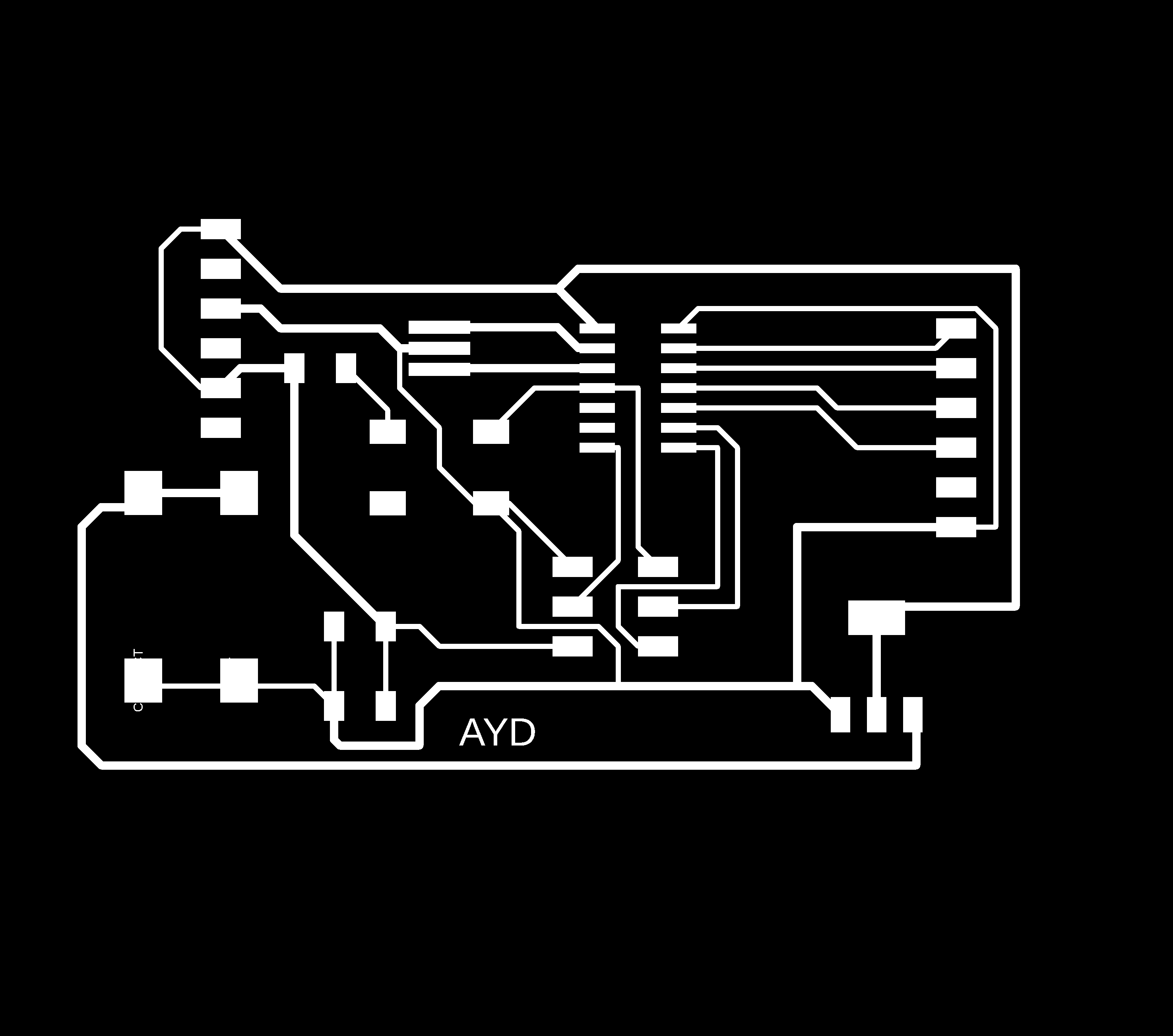
- controller_traces_png
- controller_outline_png
- driver_traces_png
- driver_outline_png
- controller_traces_rml
- controller_outline_rml
- driver_traces_rml
- driver_outline_rml
direct link