Electronics Design
Group Assignment 2022 (Raffaele Alone)
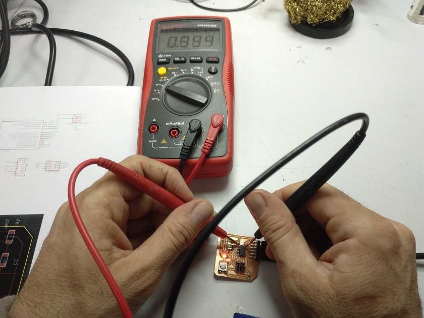
In this work I have made the current and voltage measurements of the different components of the electronic board. To make measurements of power, current, resistance, continuity, etc. We are going to use two electronic measurement tools: The multimeter and the oscilloscope.
Definition of multimeter from wikipedia: A multimeter (pronounced multimeter, also known as multitester or simply tester) is an instrument for measuring electrical quantities that integrates various functions, called "measurement ranges", in a single unit. It is presented as a box equipped with a reading window (analog dial with moving index or digital display), one or more controls placed on the front panel and at least two electrical sockets to connect the measurement probes (cables of different colors, ending with tips with insulated handle).
Definition of oscilloscope from wikipedia: An oscilloscope is an electronic display instrument for the graphic representation of electrical signals that can vary over time. It is widely used in signal electronics, often in conjunction with a spectrum analyzer. It presents the values of electrical signals in the form of coordinates on a screen, where the x-axis (horizontal) normally represents times and the y-axis (vertical) represents voltages. The image thus obtained is called an oscillogram. They usually include another input, called "THRASHER axis" or "Wehnelt cylinder" that controls the brightness of the beam, allowing to highlight or turn off some segments of the trace. Oscilloscopes, classified according to their internal workings; they can be both analog and digital, the result shown being identical in either case (in theory).
The analog multimeter is based on a galvanometer and therefore absorbs energy from the circuit under test to provide the measurement result. If it is necessary to absorb little energy from the circuit it is better to use a digital multimeter that has a higher input impedance. However, some digital multimeters have a low impedance mode to reduce the measurement error induced by external electromagnetic fields on non-energized components: the low impedance voltage measurement function is useful for finding the so-called "phantom voltages", i.e. an apparent voltage present on cables not connected to an electrical circuit.
The galvanometer is composed of a permanent magnet in which a free coil is placed to rotate perpendicularly to the magnetic field lines. By making a current circulate in the coil, a driving torque arises which tends to make it rotate; a calibrated spiral spring opposes the rotation until its resistant torque equals the driving torque; consequently, the displacement of the index is proportional to the intensity of current circulating in the coils. The full scale of the instrument is determined by its internal resistance. By connecting different resistances to the galvanometer, in parallel if the instrument is used as an ammeter or in series if the instrument is used as a voltmeter, it is possible to select the instrument full scale, by means of a key command or a rotary switch, or by moving the pins of the test leads on the various sockets present.
The analog multimeter is always equipped with a battery to be able to perform resistance measurements. The digital multimeter uses its own power supply battery for this purpose.
In an oscilloscope there are basically two types of controls that are used as regulators that adjust the input signal and consequently allow measurement on the screen and in this way you can see the shape of the signal measured by the oscilloscope, this is called In a technical way, it can be said that the oscilloscope is used to observe the signal that you want to measure.
An oscilloscope is an electronic measuring instrument for the graphic representation of electrical signals that can vary over time. It is widely used in signal electronics, often in conjunction with a spectrum analyzer.
It presents the values of electrical signals in the form of coordinates on a screen, in which the X (horizontal) axis normally represents times and the Y (vertical) axis represents voltages. The image thus obtained is called an oscillogram. They usually include another input, called "Z axis" or "Wehnelt cylinder" that controls the luminosity of the beam, allowing to highlight or turn off some segments of the trace.
Oscilloscopes, classified according to their internal operation, can be both analog and digital, the result shown being identical in either case, in theory.
In my case I am going to measure the voltage that is generated in the LED output pin of the Attiny 44.
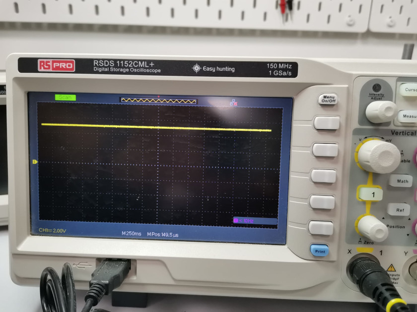
In the yellow box you can see the name of the oscilloscope used, the "RSDS 1152CML+". The blue box has also been marked, there you can see the measurement made. The grid returns a measurement of 2.00 v, and since the signal occupies 2.5 squares of the grid, we will have a voltage measurement of 5V.