6 - Electronics Design
This week's work was to design, fabricate and program the echo hello-world board by adding some extra components like a button and an LED.
Components, circuits, lab equipment… we make our first pcb and program it.
Assigments
- group project:
- use the test equipment in your lab to observe the operation of a microcontroller circuit board - individual project:
- redraw an echo hello-world board,
- add (at least) a button and LED (with current-limiting resistor)
- check the design rules, make it, and test that it can communicate
- extra credit: simulate its operation
Group assignment
The link to Group Assignments of Fab Lab León is this
A small list of necessary and useful tools in the laboratory.
Measurement tools
When working with electronic products, certain tools allow us to understand what is happening in our circuits, if there is voltage or not, what resistors we have, or capacitors… or if there is continuity in our tracks.
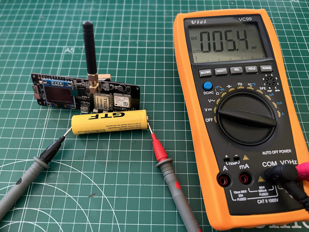
Multimeter
The first and basic tool in any electronics laboratory is the multimeter.
With it we can know what voltage (AC or DC) passes through a circuit or what is the power that is being consumed.
We can also measure electronic components, such as resistors, capacitors, transistors, diodes, LEDs…
Oscilloscope
The oscilloscope allows us to make samples and visualize what happens in our circuit in a range of time, know what is happening and detect what is happening at various points.
Oscilloscopes check and display voltage signals as waveforms and as visual representations of voltage variation over time. The signals are plotted on a graph, showing how the signal changes. The vertical axis (Y) represents the voltage measurement, and the horizontal axis (X) represents time.
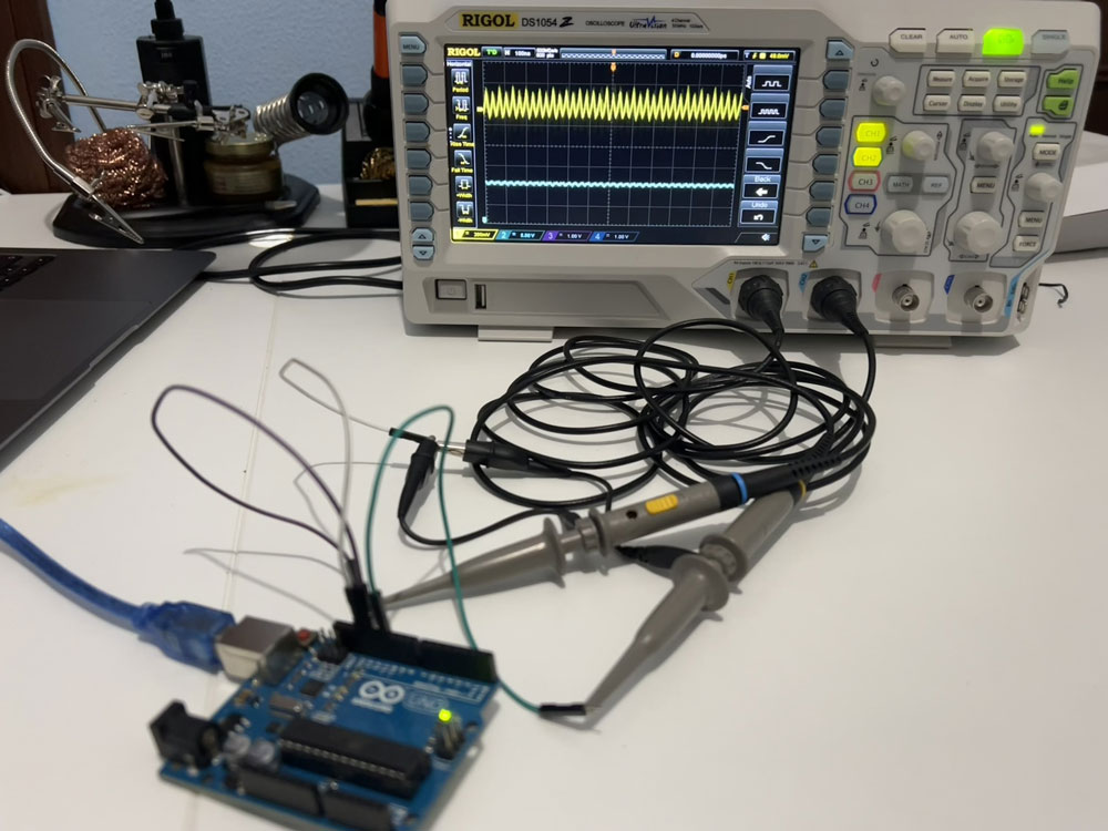
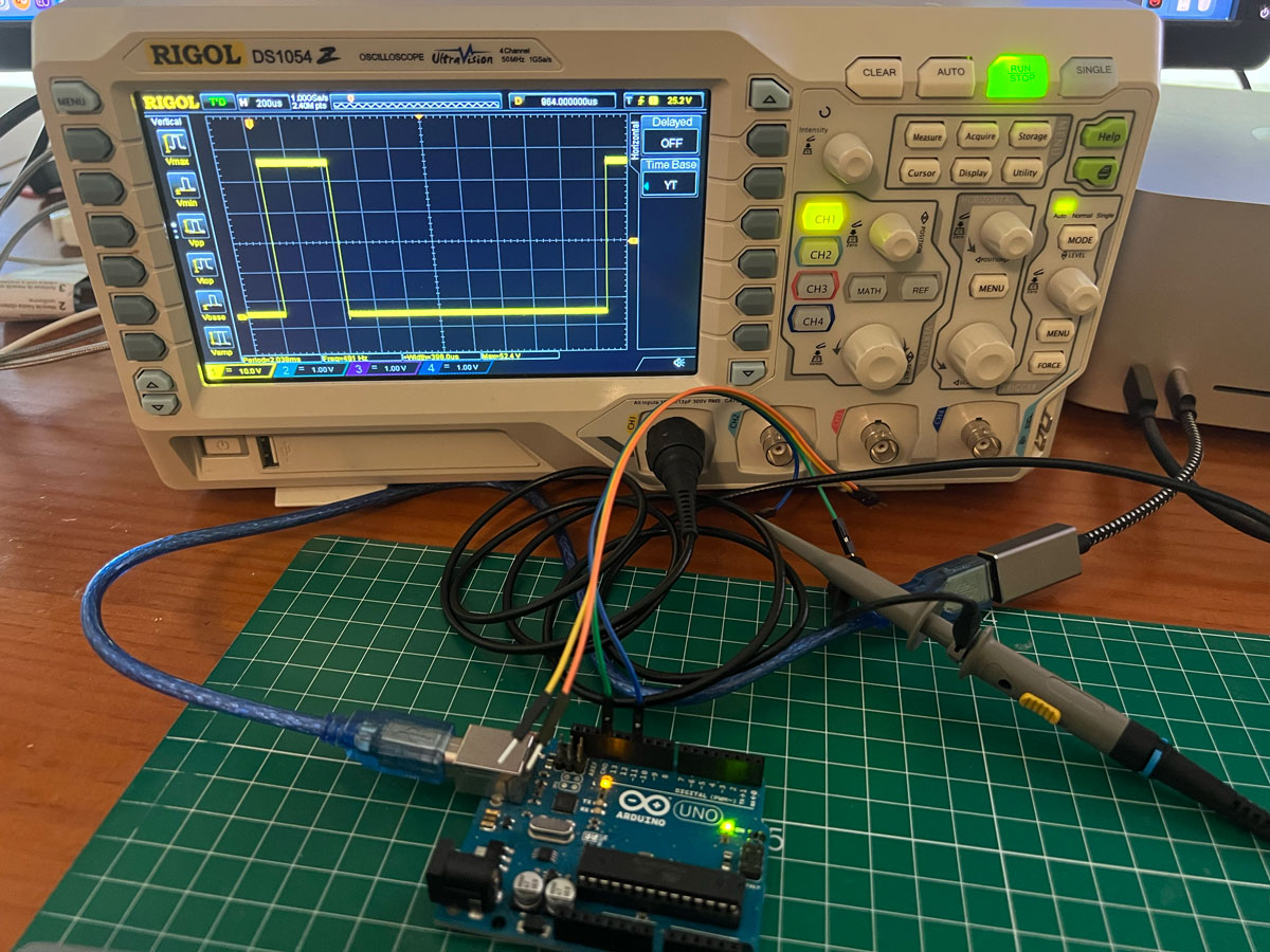
I try to show the signal PWM of a Arduino Uno.
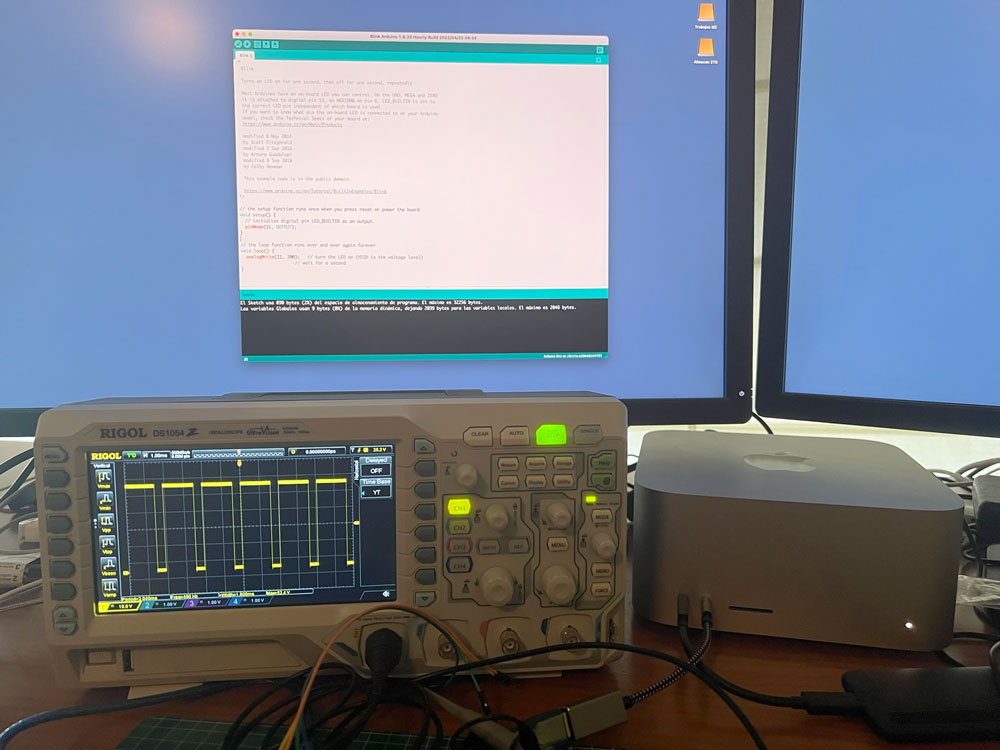
With a small code, I can send to a pin a PWM. In this case i send a value to a pin 11 with a command analogWrite(11, 50);
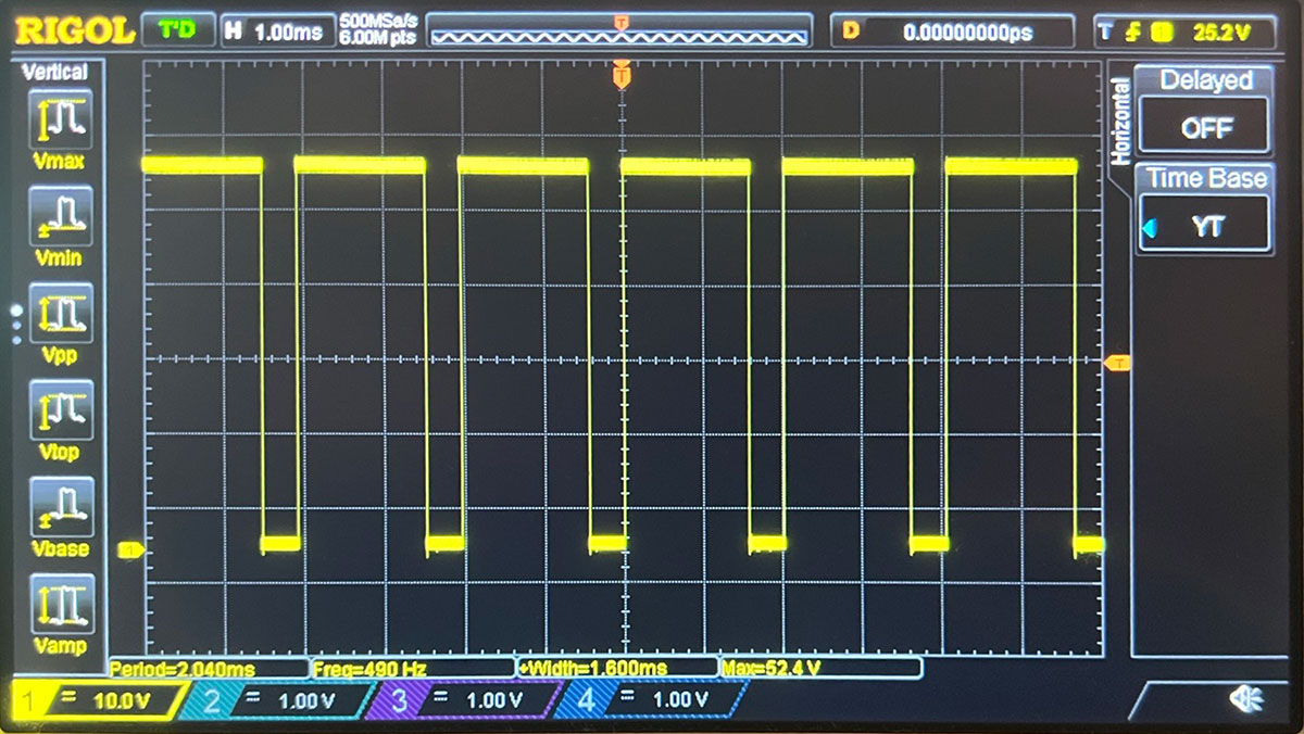
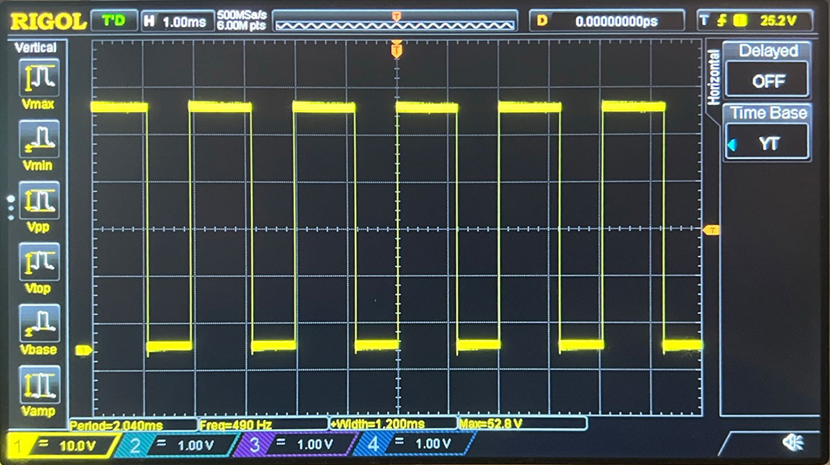
I send three values, 200, 150 and 50 for see the change of the PWM.
With PWM 200.
With PWM 150.
With PWM 50.
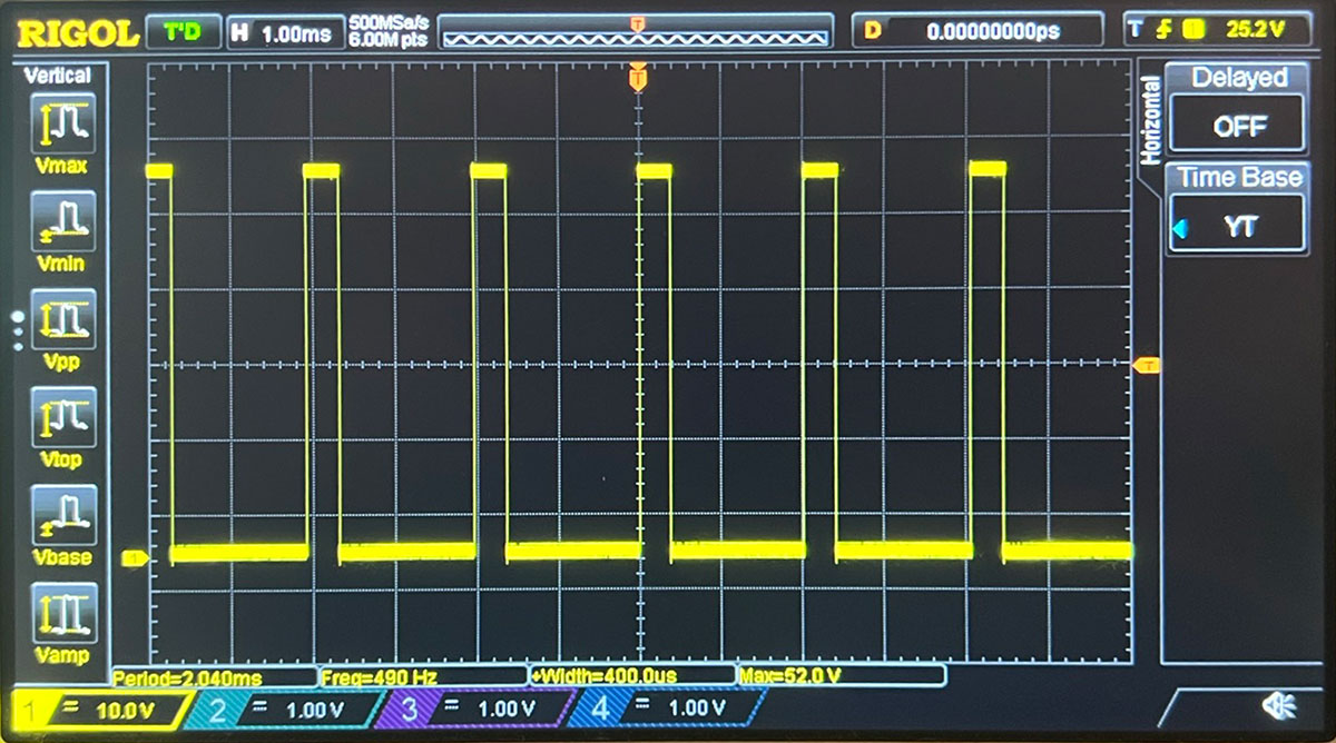
Rotate the scale knob can made a zoom of the wave, and show the period. The voltage is 5V and frequency 490 Hz in the pin 11.
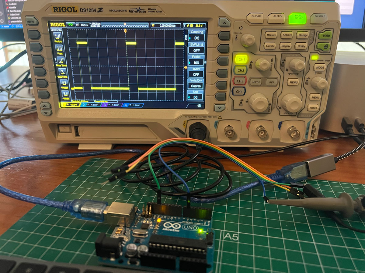
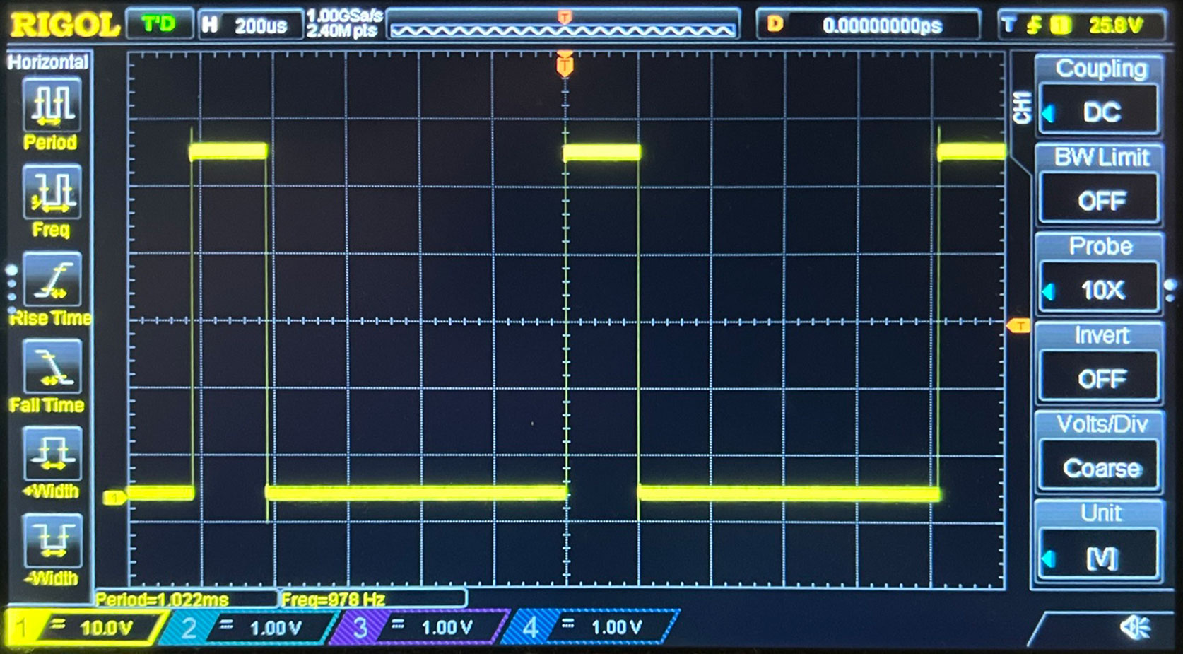
In the pins 6 and 5 the PWM Frecuency is 978 Hzs
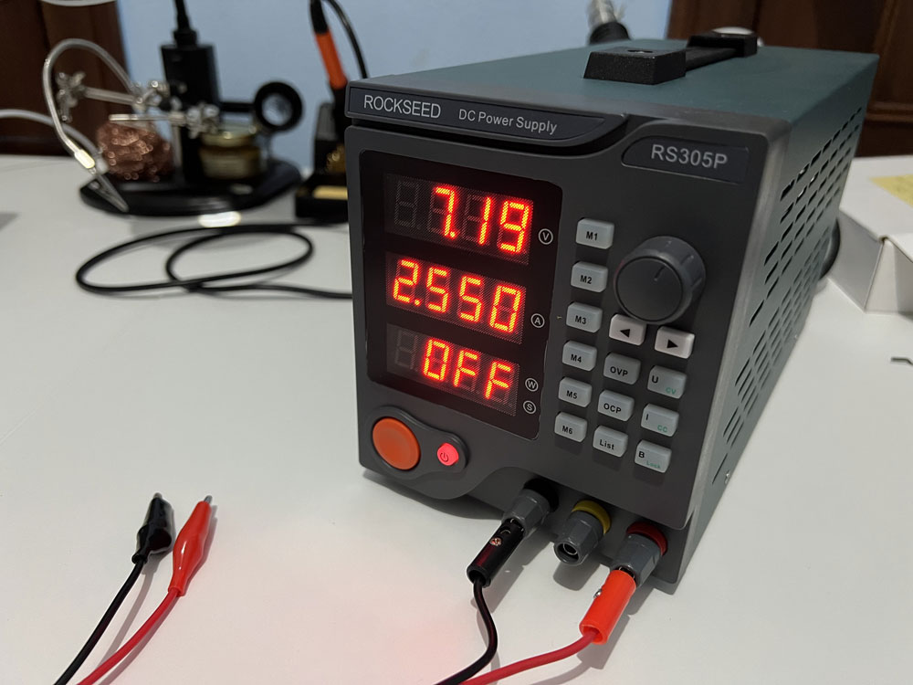
Power supply
Another good utility is a laboratory power supply, which allows us to achieve a certain voltage range, in order to power our boards, or even simulate how it would work with different powers. By default we can output +5V and a range +-X Volts.
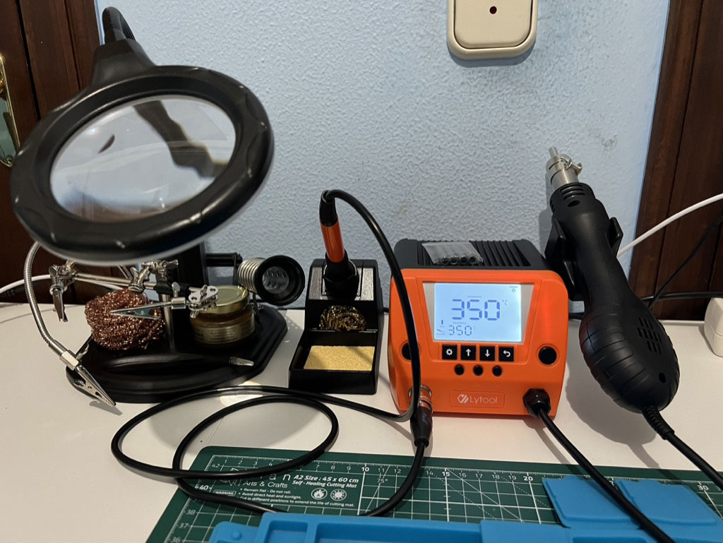
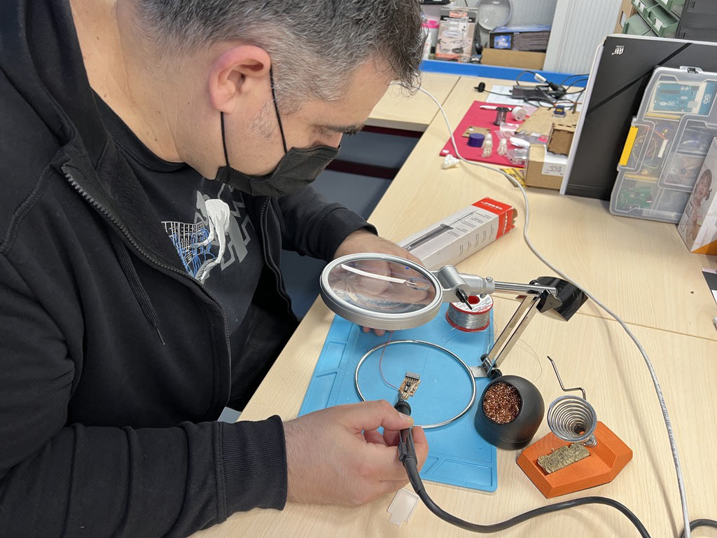
Soldering station
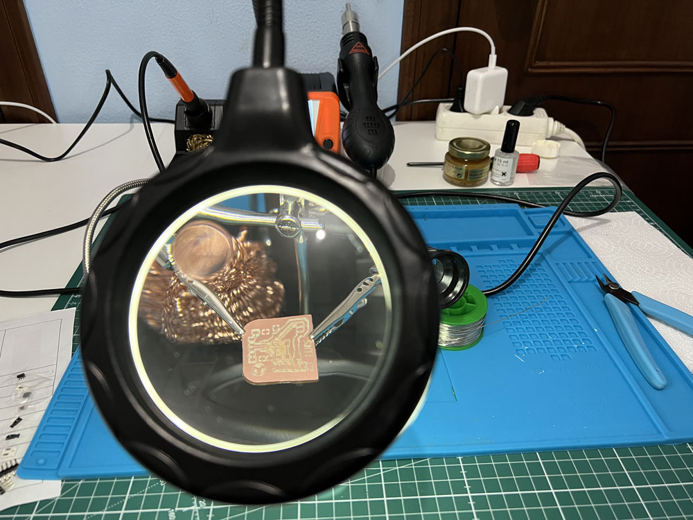
To work in our case with SMD components, it is ideal to have a good soldering station.
In my case, both with a soldering iron and with hot air, which is very comfortable when soldering very small components.
And have an auxiliary hand augmentation station nearby
Individual Assigment
This week need made a programmer FTDI for use with us projects.
SAMD 11C
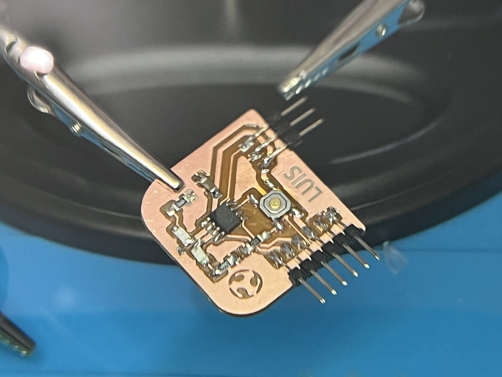
At Fab Lab León they gave me the materials to make Neil’s USB-D11C-Serial programmer.
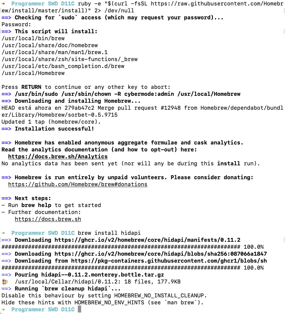
Install hidapi on Mac
Hidapi is a library for communicating with USB and Bluetooth HID devices App website: https://github.com/signal11/hidapi Install the App
-
Press Command+Space and type Terminal and press enter/return key.
-
Run in Terminal app:
ruby -e "$(curl -fsSL https://raw.githubusercontent.com/Homebrew/install/master/install)" 2> /dev/null
and press enter/return key. If you are prompted to enter your Mac’s user password, enter it (when you type it, you wont see it on your screen/terminal.app but it would accept the input; this is to ensure no one can see your password on your screen while you type it. So just type password and press enter, even if you dont see it on your screen). Then wait for the command to finish. -
Run:
brew install hidapi
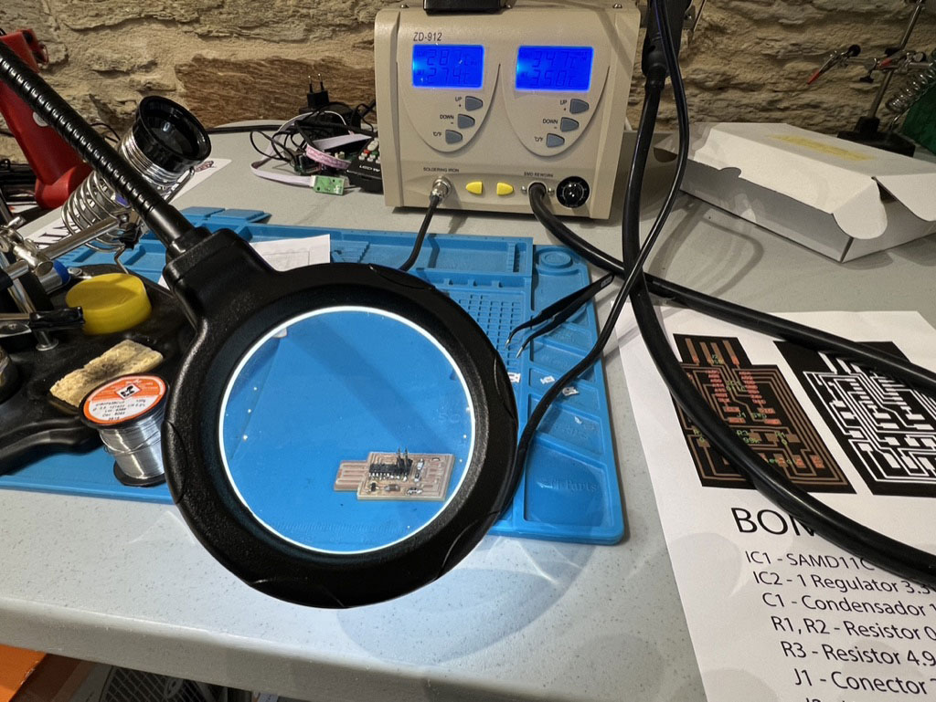
Bootloader SAMD 11C
Friday 4 - I try programm with the help of Adrian Torres, but the 3.3V Regulator dont work good, i will wait until my travel to León for replace and repair the pcb and try program again.
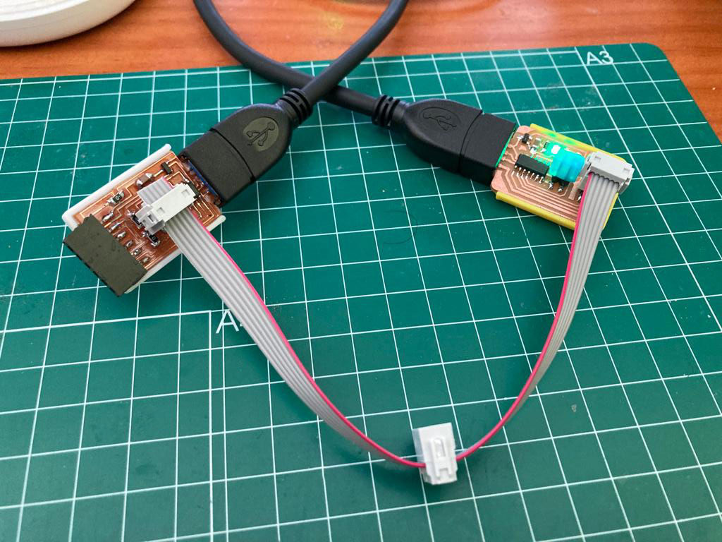
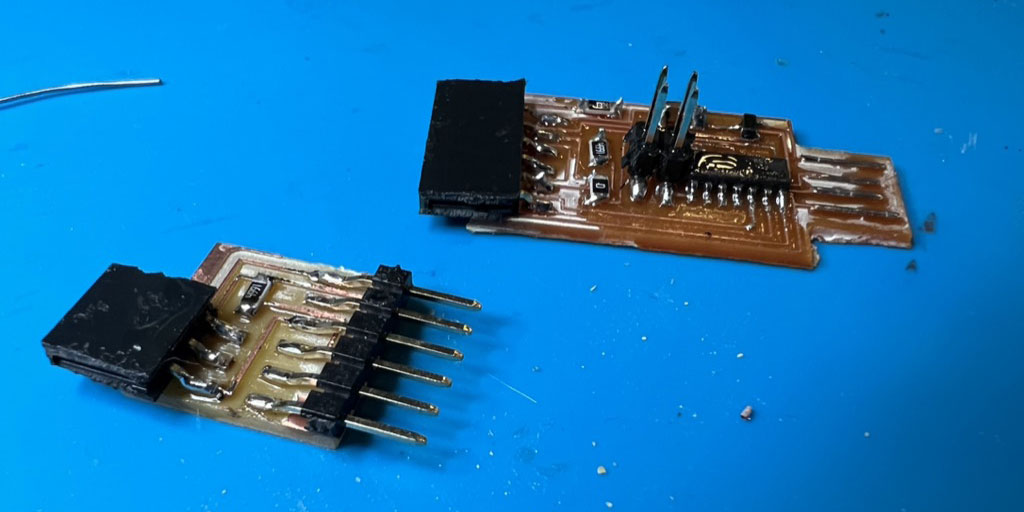
On Wednesday, March 9, after arriving in León, and checking the pcb with Adrian, he realizes that the GND track was cut when milling the cutting line. So we soldered a wire to join the GND of the USB to the rest of the circuit.
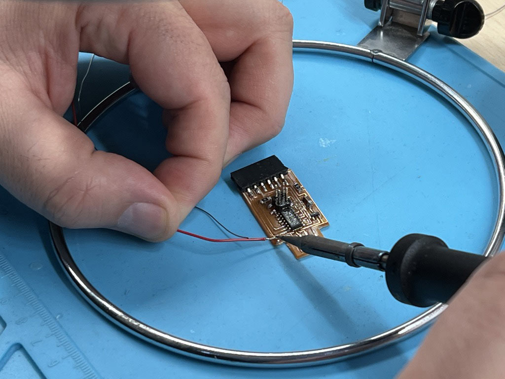
And finally we can program it correctly.
Ohm´s law
Ohm’s law: R = V / I
V = R x I
- Current (I)= amount of electrons coming through
- Voltage (V)= push of the current
- Resistance (R)= measured in ohm.
For calculator the Resistance for a LED of 3V and 20mA in a circuit of 5V will use this:

Hello Attiny412
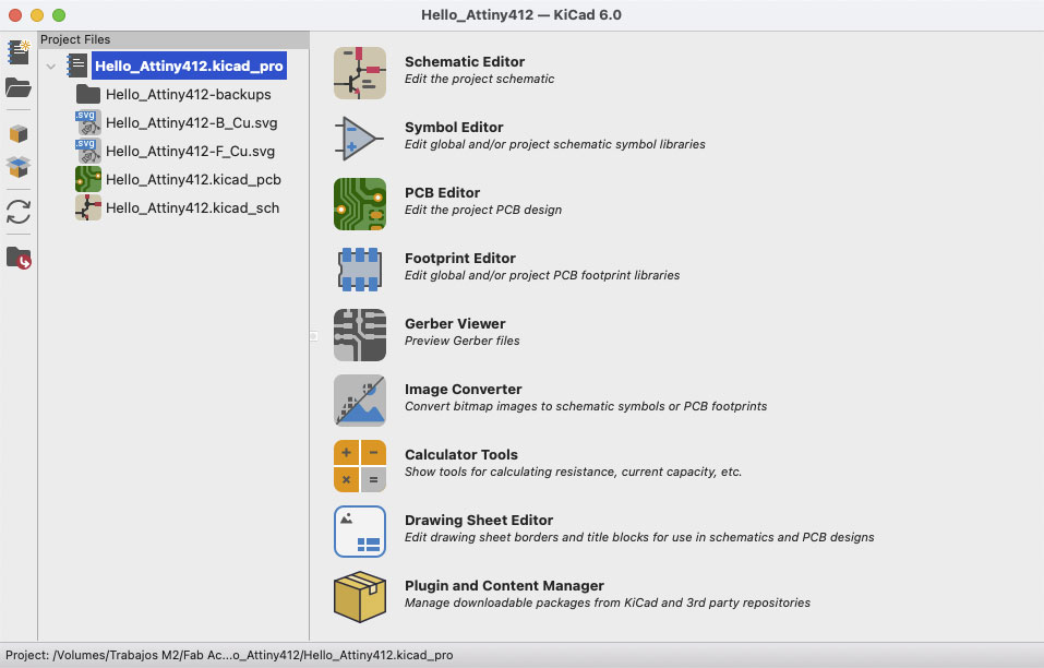
This week i will made a Hello Word PCB of a Attiny 412. I use KiCad v6 for desing the PCB. Years ago I use KiCad for made a PCb, dont is dificult, but the version 6 is more easy and work very good. For now is a Intel version for Mac, but work perfect in M1 too.
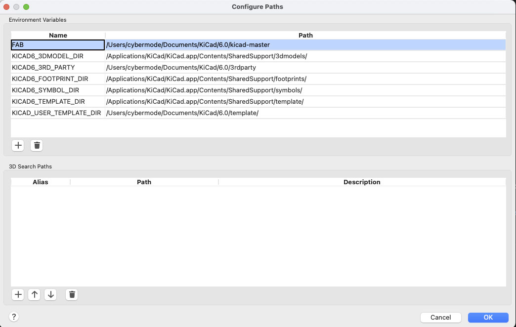
Fab Electronics Library for KiCad
I import the Fab Electronics Library for KiCad, clone the git and place in my user>documents>KiCad folder.
In KiCad go to menu “Preferences” and select “Configure Paths…” add a new Path call FAB and select the clone folder.
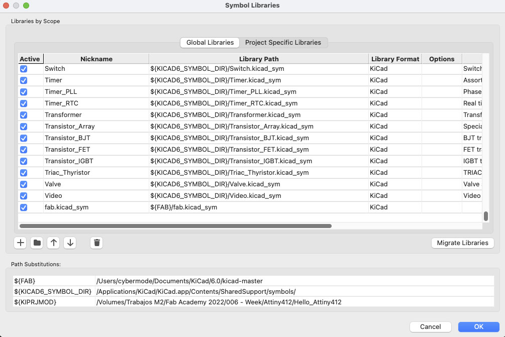
After this in “Preferences” > “Manage Symbol Libraries…” and add “fab.kicad_sym”
After this in “Preferences” > “Manage Footprint Libraries…” and add “fab.pretty”
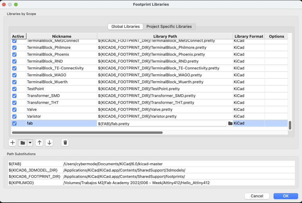
*** Important, The nickname must be “Fab” for KiCad to recognize the footprints
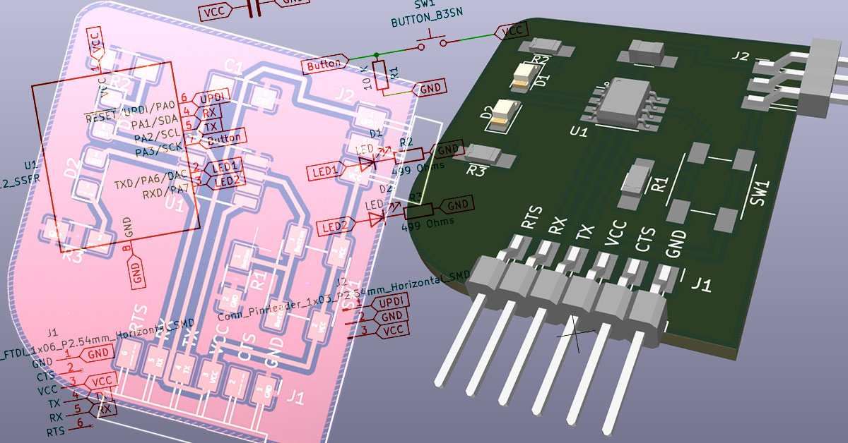
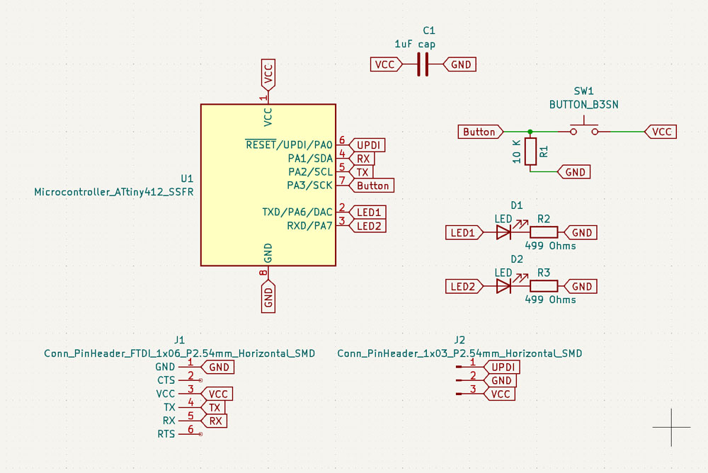
Schematic
After config KiCad I made a new document and start to draw the schematic.
This is the list of components I will use.
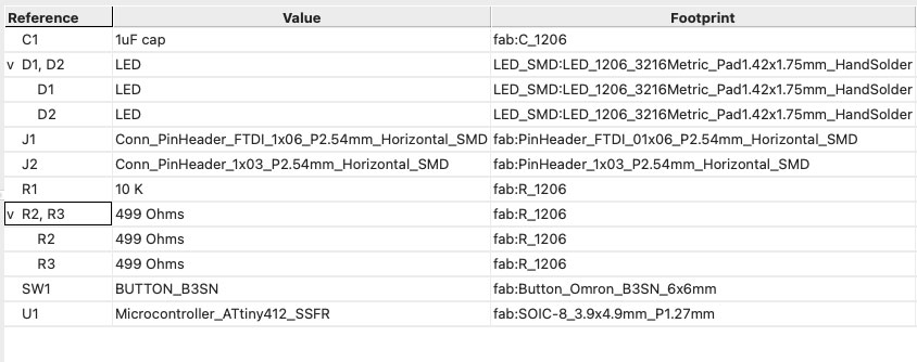
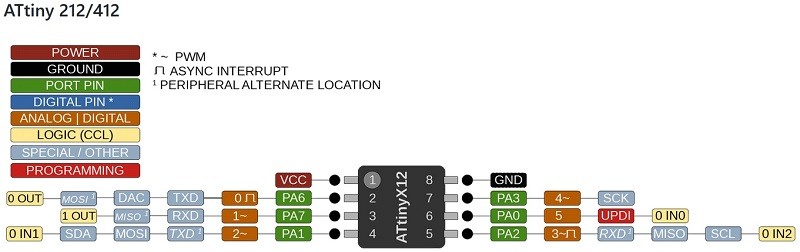
I use 2 led for made a traffic light. In PA6 and PA7 I will connect the Leds, and use the PA3 for read the button state
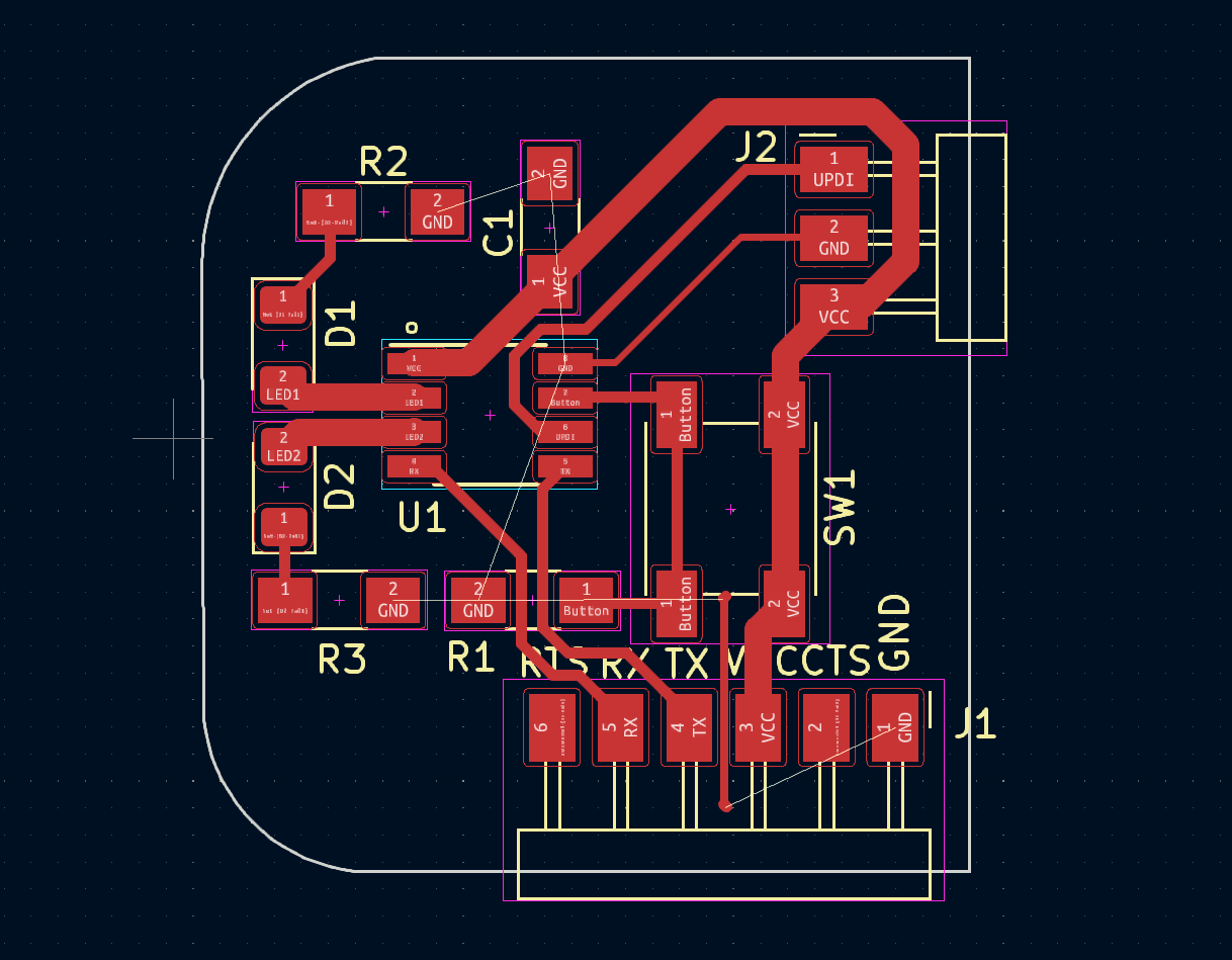
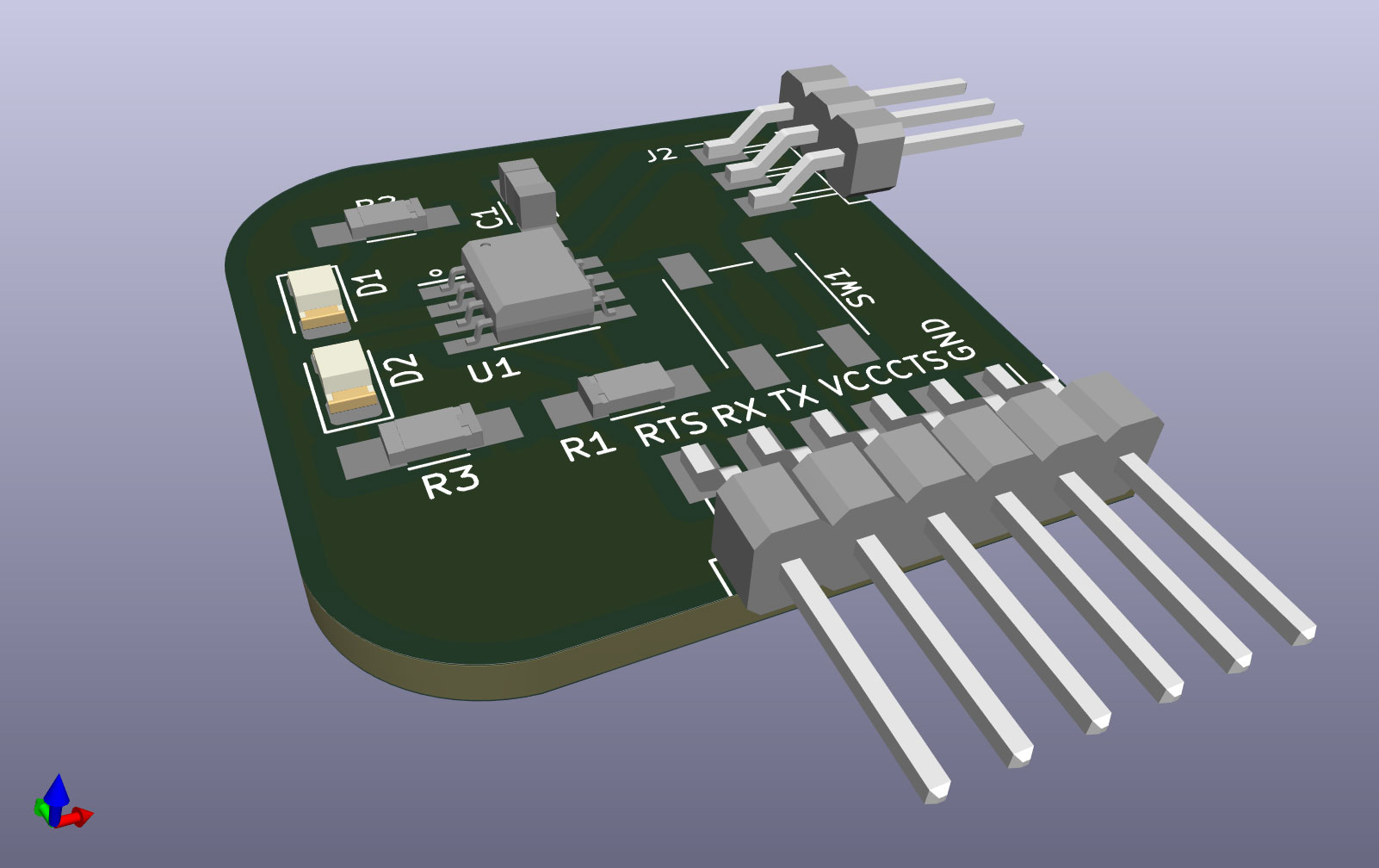
Footprint
After have done the schematic I send to PCB editor, than I need set the footprint to any symbol.
I use the footprint of Fab Electronics Library. And made the PCB.
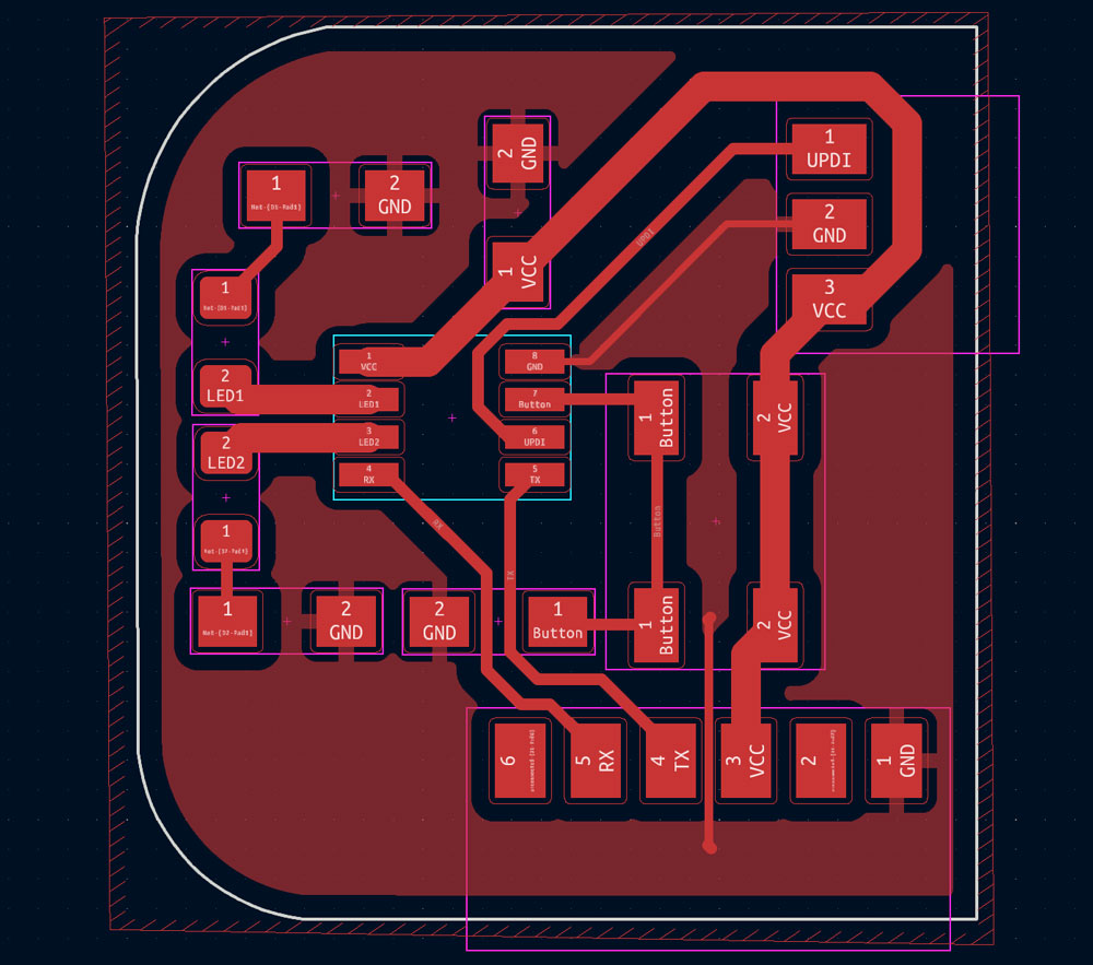
Fill Zones
For made a fill zone with GND I use the “add a filled zone” tool.
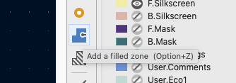
Need draw the fill zone, when start to draw the program ask what layer will be the filled zone, and can edit the clearance, minimun width….
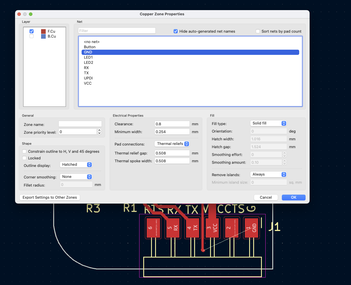
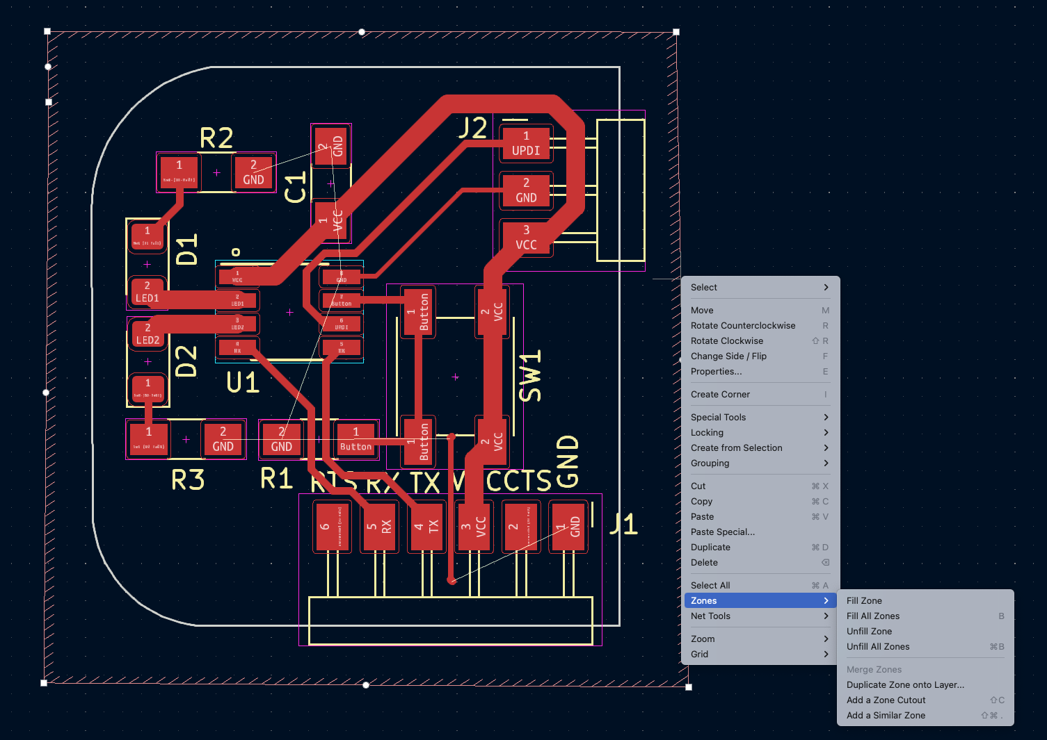
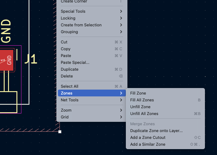
And for fill the zone, with the right button of mouse click and KiCad calculate the zone. Need made this allways you edit the pcb, and modify the route tracks, footprints position…
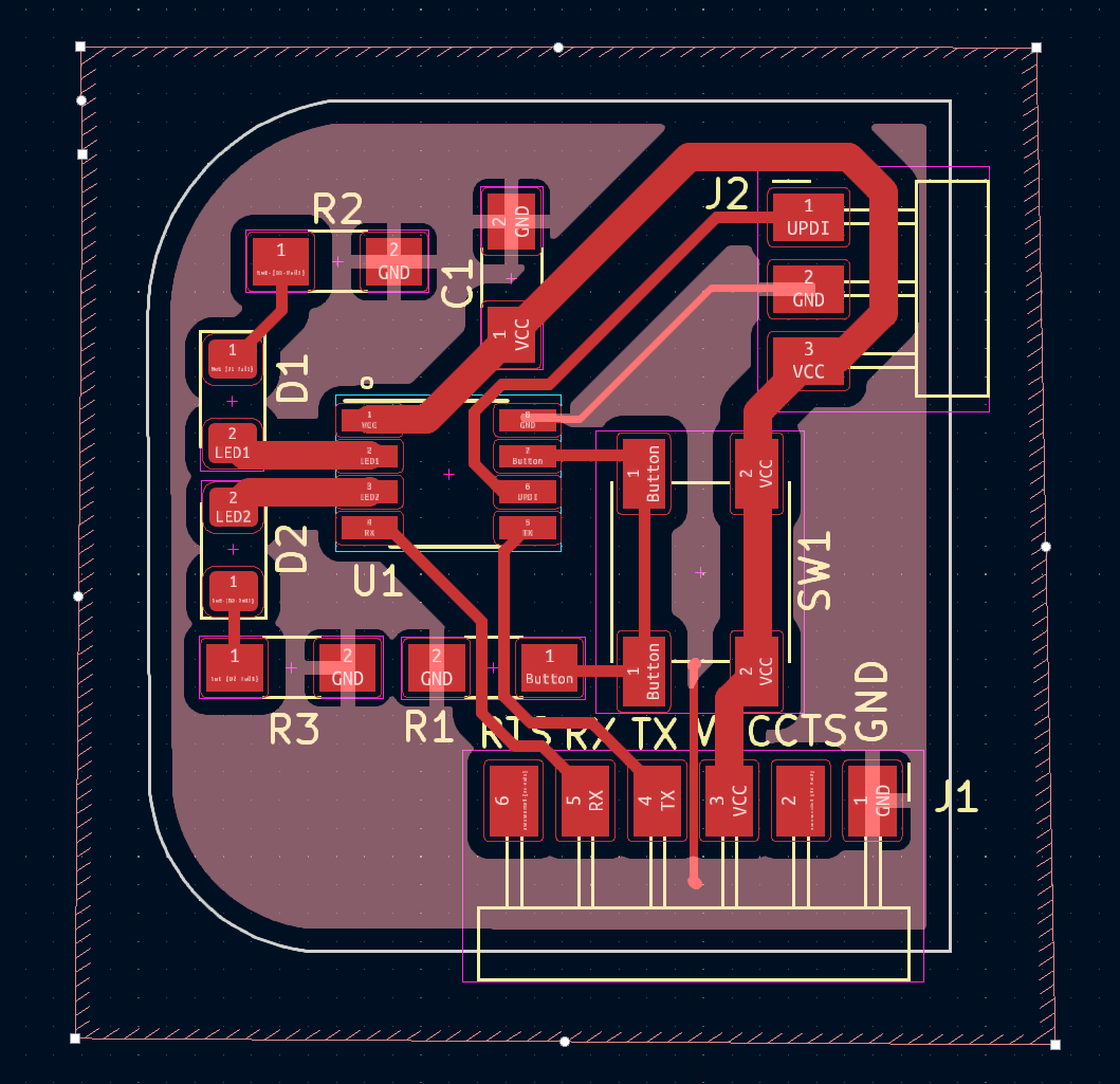
This is my first verion of the PCB.
After show to my friend Luis Miranda of A Industriosa, he sayme the tips for desing a PCB:
- No 90º Angles
- The V´s tracks made with more width possible.
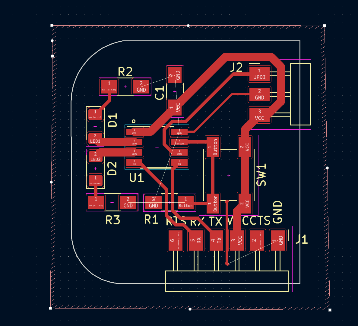
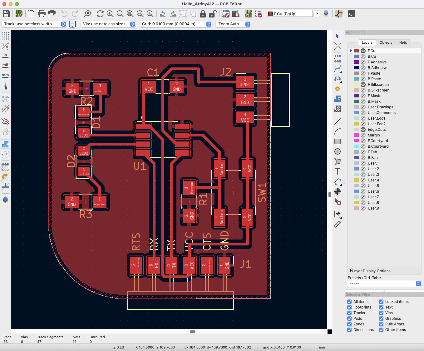
And I redraw the PCB.
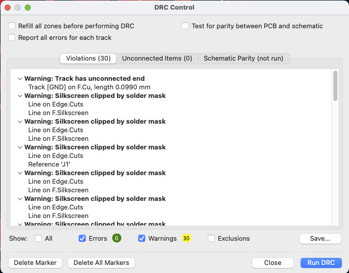
Af ther design I check if have any error with Design Rules Checker.
From Export menu I made the SVG files, but I need convert to png and rasterize in Illustrator again for made good in easel.
In Photoshop I add too the Fab Lab logo and my name. When the image is done, I export to PNG and open in Adobe Illustrator for rasterize again and export to .svg.

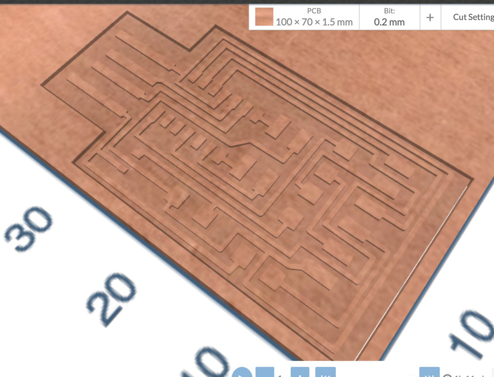
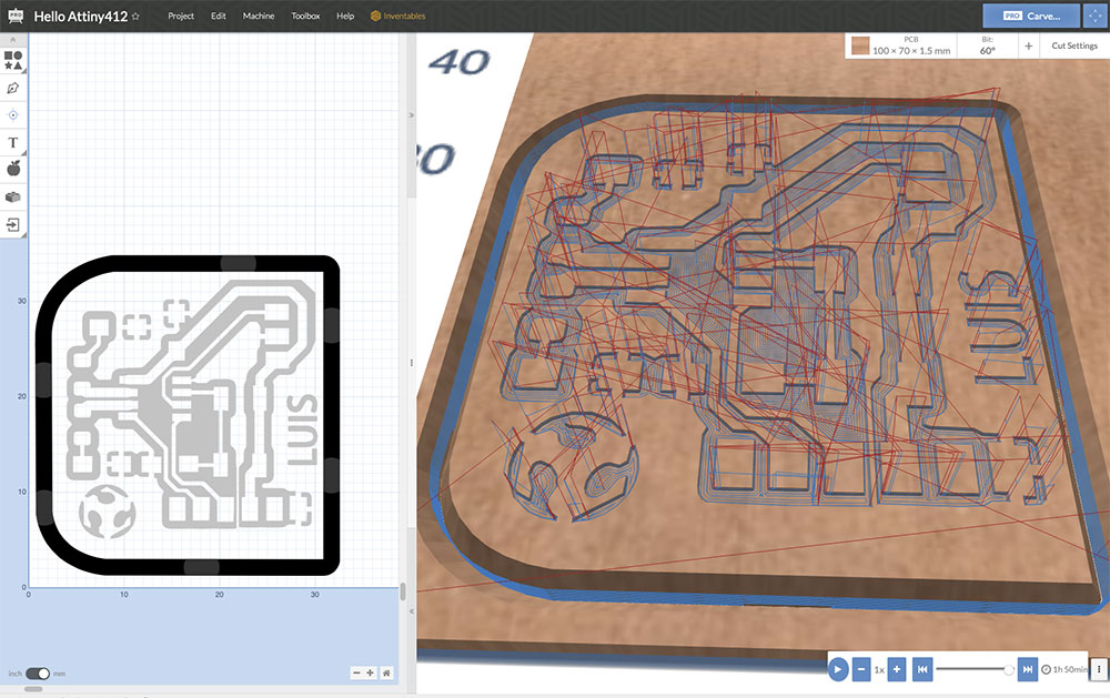
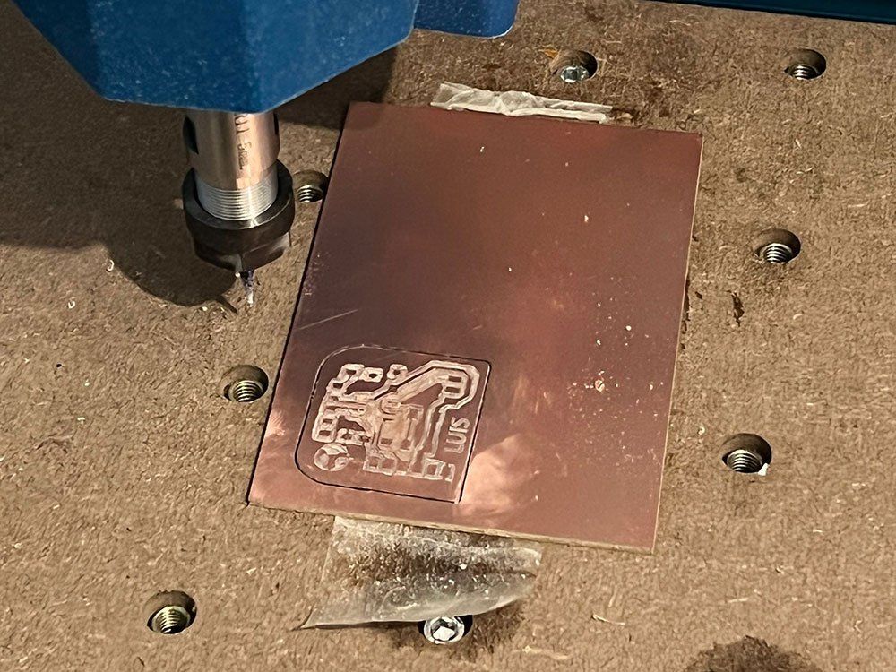
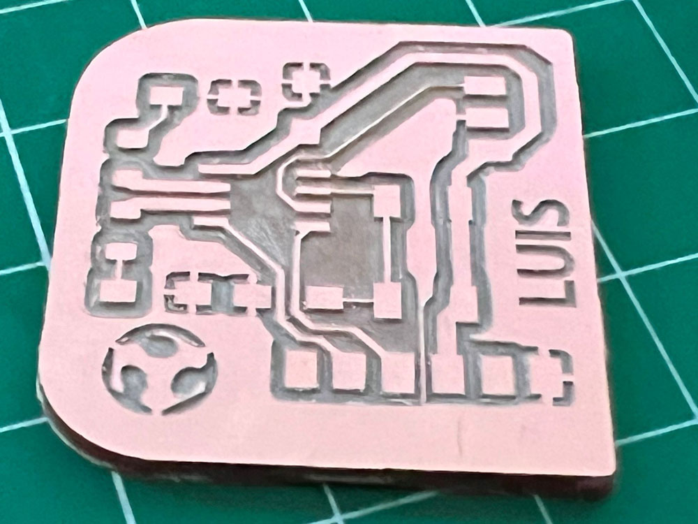
Making the PCB
After have the new .svg I open in Easel and made milling settings. I set the Depth per pass to 0.1 mm, and made a nice milling after 2 hours.
Programming Arduino
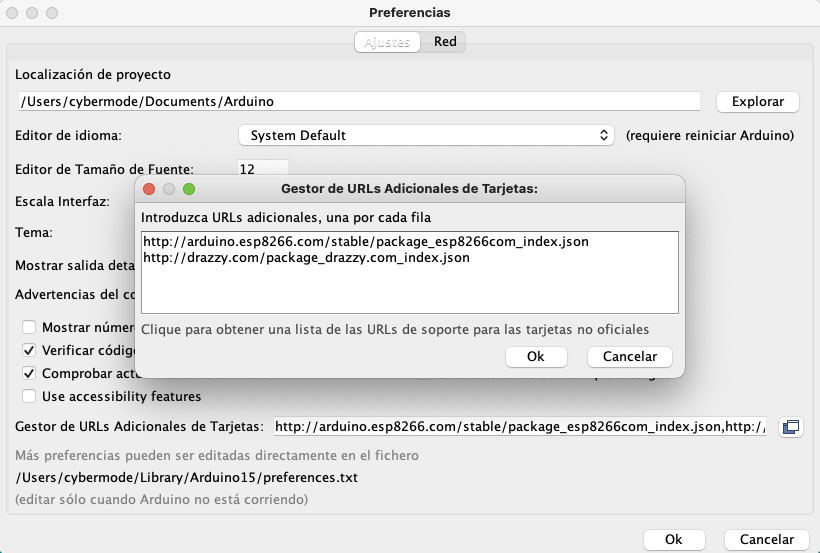
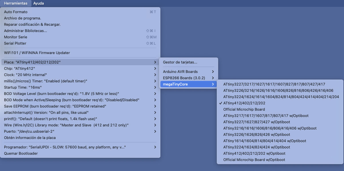
For setup Arduino IDE I need add the libraries of ATtiny from preferences with the url:
http://drazzy.com/package_drazzy.com_index.json
After active the library megaTinyCore can select ATtiny412/402/212/202
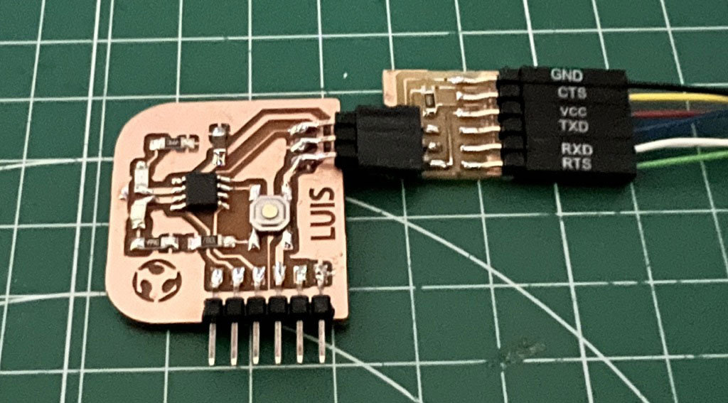
The programer than I use is a FTDI, need select SerialUPDI - SLOW:57600 baud, any platform, any voltage, any adapter.
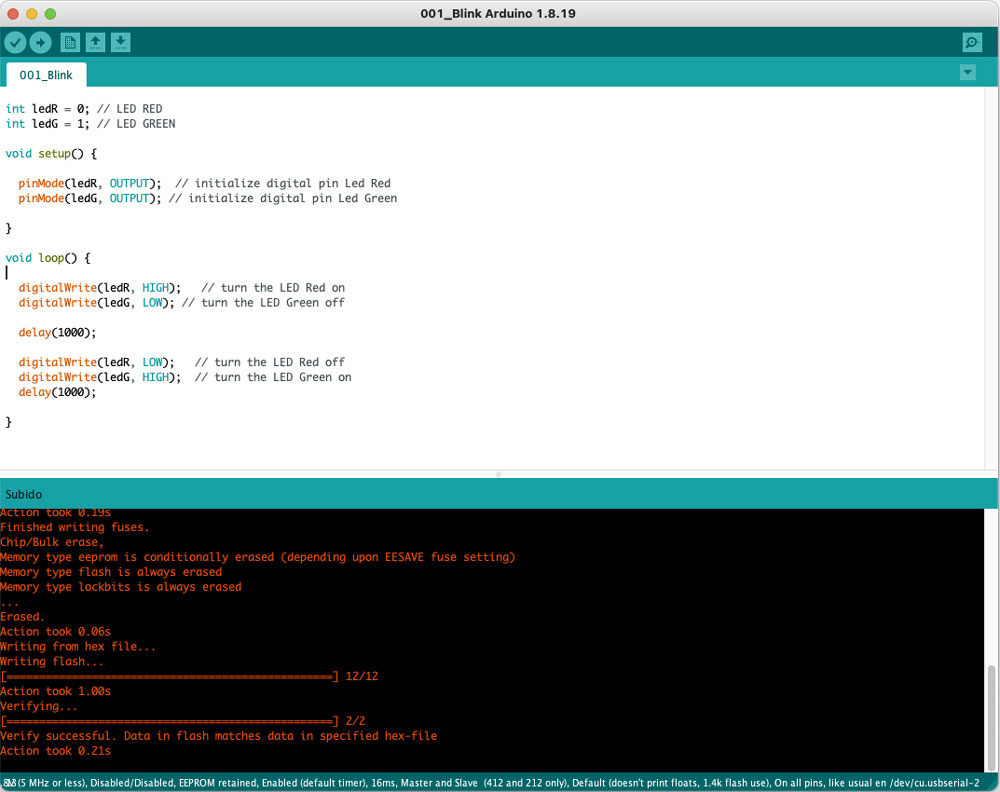
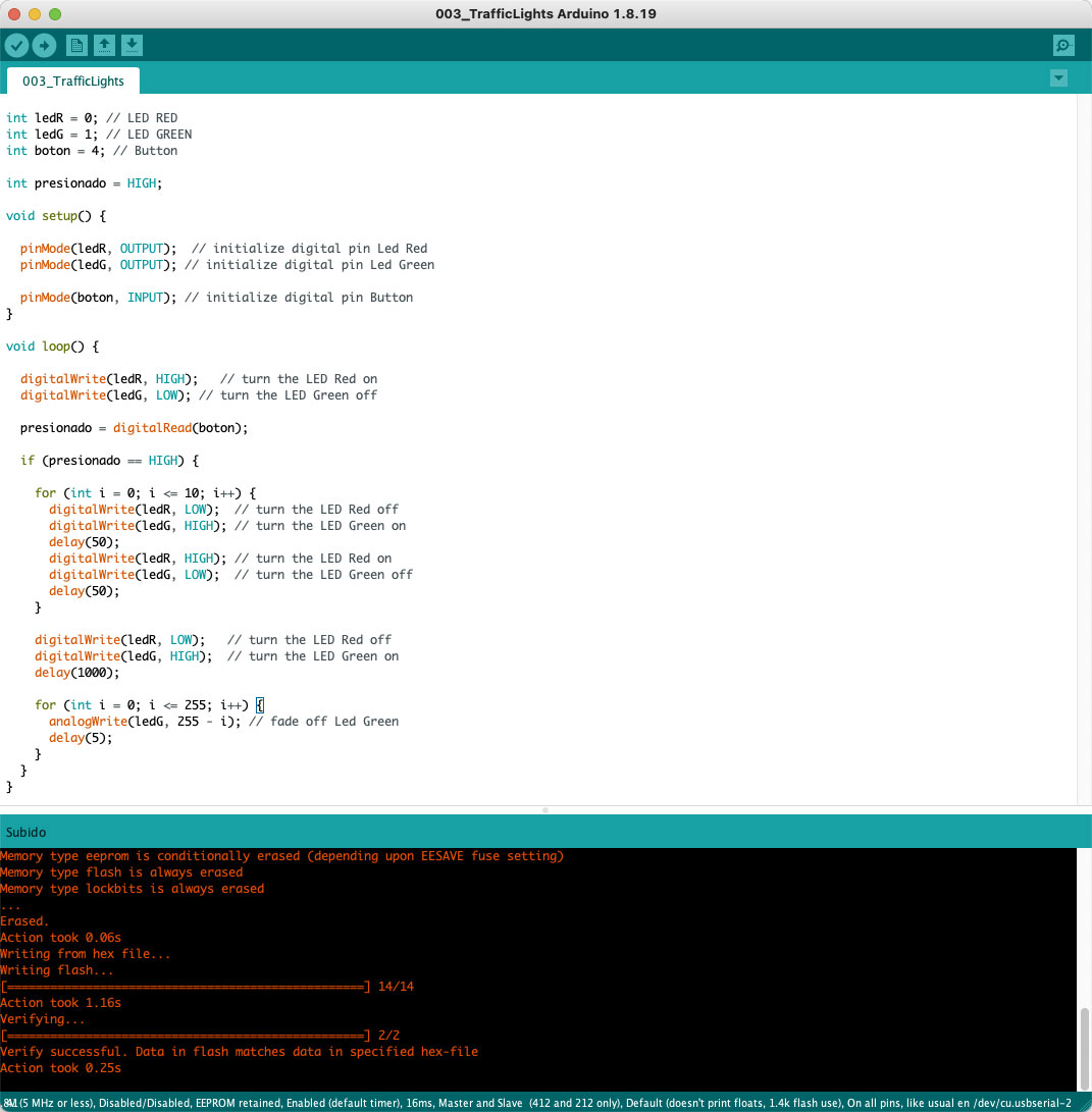
The first test of programig I made a simple Blink, turn on/off the leds with digitalWrite and wait a second delay(1000).
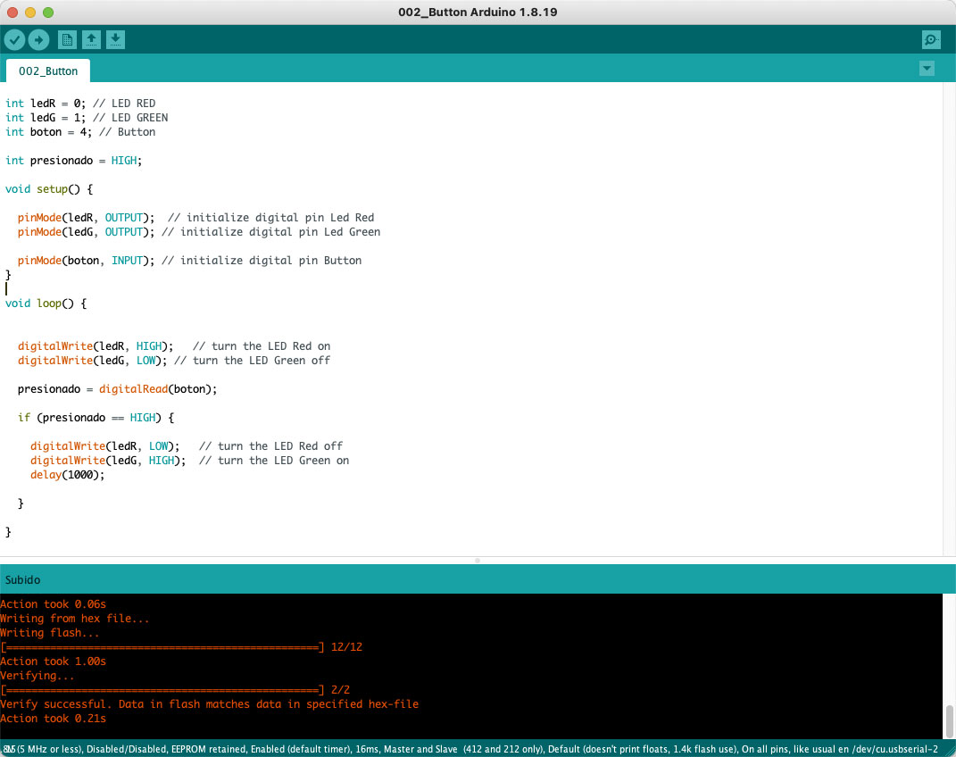
For read the state of button I use the digitalRead and a condition, if is press change the leds on and off.
The PIN´s 1, 2, 3 and 4 are PWM but only the Led Green is in one of this (1). I add a fade off of the Led Green with a for.
Downloads
Arduino 001_Blink
Arduino 002_Button
Arduino 003_TrafficLights
Explore more like this
17 - Invention, Intellectual Property, and Income
This is the last week before I present the final project, I already have a slide and video proposal of my project.
16 - Applications and Implications
Propose a final project masterpiece that integrates the range of units covered, answering: