Interface and application programming
Write an application that interfaces a user with input and/or output device(s) on a
board that you made.
Group assignment:
Group Assignment
In the following I will describe and compare 3 tool options for creating GUI's that can interface a user with a pcb+microcontroller:
- Python with PySerial and Tkinter: One option is to use Python with the PySerial and Tkinter libraries, which allows you to create a GUI that communicates with the PCB over a serial connection. PySerial provides a way to communicate with the PCB via serial, while Tkinter allows you to create a GUI for the user to interact with the PCB. You can use Tkinter to create buttons, sliders, and other widgets to send commands to the PCB and receive data back. This is the option our instructor Marcello Tania showed us in the local lecture and which I then used for this weeks assignment. It was the first optin I really learned about and I liked working with it. It was quite easy to create a quick and simple GUI. With the help of other libraries you can also make it look a bit prettier. Which I would recommend if you have the time.
- MATLAB GUI with Instrument Control Toolbox: MATLAB also has the tools to create a GUI that can communicate with an Arduin or self made PCB's. The Instrument Control Toolbox provides a set of tools for communicating with a wide range of instruments, including PCBs. MATLAB's GUI development environment allows you to create a graphical user interface for the user to interact with the PCB. You can use MATLAB's plotting tools to display data received from the PCB and control elements like buttons and sliders to send commands to the PCB. MATLAB is a very good program in general, but you need a license. I got one through my university otherwise there is a 30-day test period.
- Pythonista is an integrated development environment (IDE) for iOS devices that
allows you to
write and run Python code directly on your iPhone or iPad. It provides a Python interpreter,
a code editor, and a range of built-in libraries, as well as support for external libraries
and modules.
Similar to creating a GUI with MATLAB, you can also create a GUI with Pythonista using a module called "ui". The "ui" module provides a set of widgets and layout managers that you can use to create graphical user interfaces on iOS devices. These widgets include buttons, labels, text fields, sliders, and more. Like with tkinter, you can use the "ui" module to create custom layouts for your GUI, set widget properties such as colors and fonts, and manage the placement and behavior of the widgets. And, just like with tkinter, you can also use Python code to add custom functionality to your app, such as sending and receiving data over a serial connection. Overall, Pythonista provides a powerful platform for developing GUI apps on iOS devices, and its support for external libraries and modules allows for a wide range of functionality and customization. Since I on an iPhone this is very helpful when I want to control a board using my phone without having to develop an app.
Programming a GUI
For this assignment, our instructor Marcello Tania showed us how to I write code in Jupyter
notebook using the
Anaconda distribution of Python. The code uses the Tkinter library to create a window with a
button that toggles the
builtin LED of my XIAO Seeeduino SAMD21
on and off when clicked.
As well as a mode for blinking the LED until turned off. (The following code was written
with the help of Marcello Tania + ChatGPT + edited by me)
Anaconda is a distribution of Python and other scientific computing packages that
provides a
convenient way to manage your Python environment and install additional packages.
Jupyter is an open-source web-based interactive computing environment that allows you to
create
and share documents that contain live code, equations, visualizations, and narrative text. It is
often used for data science and machine learning tasks.
Tkinter is a standard Python library for creating graphical user interfaces (GUIs) and
comes
pre-installed with most versions of Python. It provides a set of tools and widgets that allow
you to create windows, buttons, labels, text boxes, and other GUI elements.
Arduino IDE code:
You need to upload this code to your board. For more detail, view Embedded Programming Assignment.It sets up a basic communication between computer and board via a serial connection. It uses the Serial library to set up the serial communication at a baud rate of 9600.
It also sets the LED_BUILTIN pin as an output pin using the pinMode() function. The loop() function runs repeatedly and checks if there is any incoming serial data available. If there is, it reads the data using the Serial.read() function and stores it in the incomingByte variable. If the incoming byte is 'H', it turns on the LED by setting the LED_BUILTIN pin to HIGH using the digitalWrite() function. If the incoming byte is 'L', it turns off the LED by setting the LED_BUILTIN pin to LOW.
							void setup() {
	// put your setup code here, to run once:
	Serial.begin(9600);
	pinMode(LED_BUILTIN, OUTPUT);

	}

	void loop() {

	byte incomingByte;
	// put your main code here, to run repeatedly:
	//see if theres incoming serial data

	if(Serial.available() > 0){
		incomingByte = Serial.read();
		if(incomingByte == 'H'){
		digitalWrite(LED_BUILTIN, HIGH);
		}
		else if(incomingByte == 'L'){
		digitalWrite(LED_BUILTIN, LOW);
		}
	}
	}
Jupyter Notebook code:
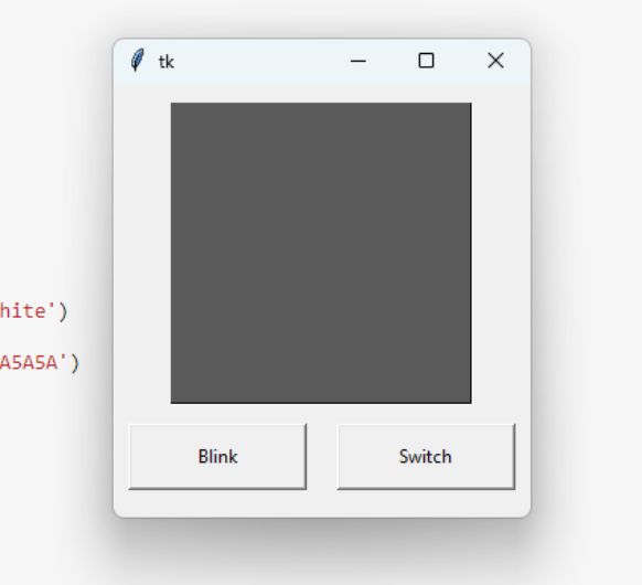
You can insert the code into Jupyter Notebook and execute it with Shift+Enter. This code creates a graphical user interface (GUI) using the Tkinter library to interact with an LED connected to an Arduino board.The GUI includes a canvas with a rectangle, two buttons for switching the LED on and off or blinking it, and a serial connection to the SAMD21. The program first sets the initial states for the color and blinking of the LED, and then defines two functions - myBlink() and mySwitch() - for controlling the LED based on user input.
The myBlink() function causes the LED to blink at regular intervals, while the mySwitch() function turns the LED on and off as well as changes the color of the canvas. The code also sets up the connection to the Arduino board and runs the main loop to continuously update the GUI and respond to user input.
							from tkinter import *
import serial
import time

# Set the window size
window = 200

# Set the initial color state and blink state
colour_state = 0
blink_state = False

# Create the root window
root = Tk()

###################

# Set up the serial connection to the SAMD21 (the port depends,
you can check it inside your Arduino IDE)
ser = serial.Serial('COM3', 9600)
ser.setDTR()
ser.flush()

###################

# Function to blink the LED
def myBlink():
    global blink_state
    blink_state = not blink_state

    # Inner function to actually blink the LED
    def blink():
        if blink_state == True:
            # Turn the LED on and change the canvas color
            ser.write(b'H')
            myCanvas.itemconfigure('rect', fill="#5A5A5A")
            myCanvas.update()
            root.after(500)
            # Turn the LED off and change the canvas color back
            ser.write(b'L')
            myCanvas.itemconfigure('rect', fill="#FDFD96")
            myCanvas.update()
            # Schedule the next blink
            root.after(500, blink)
        else:
            # Turn the LED off
            ser.write(b'L')

    # Start the blinking process
    blink()

# Function to switch the LED on/off
def mySwitch():
    global colour_state, blink_state

    # If the LED is currently blinking, stop the blink
    if blink_state:
        blink_state = False

    if colour_state == 1:
        # Turn the LED off and change the canvas color
        myCanvas.itemconfigure('rect', fill="#5A5A5A")
        colour_state = 0
        ser.write(b'H')
        time.sleep(0.1)
    else:
        # Turn the LED on and change the canvas color
        myCanvas.itemconfigure('rect', fill="#FDFD96")
        colour_state = 1
        ser.write(b'L')
        time.sleep(0.1)

    # Update the canvas
    myCanvas.pack()


# Create canvas widget
myCanvas = Canvas(root, width=window, height=window, background='white')
# Create rectangle on the canvas
myCanvas.create_rectangle(0,0,window,window, tags='rect', fill='#5A5A5A')
# Pack the canvas with padding
myCanvas.pack(pady=10)

# Create frame for buttons
buttonFrame = Frame(root)
buttonFrame.pack()

# Blink button widget
myButtonBlink = Button(buttonFrame, text="Blink", command=myBlink, padx=20, pady=10, width=10)
myButtonBlink.pack(side=LEFT, padx=10)

# Switch button widget
myButtonSwitch = Button(buttonFrame, text="Switch", command=mySwitch, padx=20, pady=10, width=10)
myButtonSwitch.pack(side=LEFT, padx=10)

# Run the main loop
root.mainloop()
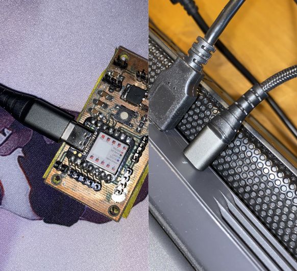 Connect the PCB to your PC.
 Start the GUI with
Shift+Enter. Make sure that you have previously uploaded the Arduino Code to your PCB.
Start the GUI with
Shift+Enter. Make sure that you have previously uploaded the Arduino Code to your PCB.