Computer-Controlled Cutting
Design, lasercut, and document a parametric press-fit construction kit, which can be
assembled in multiple ways. Account for the lasercutter kerf.
Cut something on the vinylcutter.
Group
assignment:
Group assignment
The lasercutter we use at the FabLab in Kamp Lintfort is the Epilog Fusion and the Epilog Fusion Zing. The goal of this weeks group assignment was to learn more about the lasercutter at our local FabLab and to characterize it's properties. For this assignment I mainly used the Epilog Laser Fusion (60 Watts).
Epilog Laser Fusion 60 Watts:
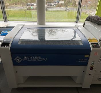 The laser
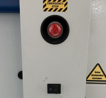 The button to turn
it on and emergency stop
The button to turn
it on and emergency stop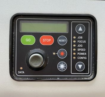 Control panel to set jog, focus, job etc. Move joycon to change
and press joycon to set.
Control panel to set jog, focus, job etc. Move joycon to change
and press joycon to set.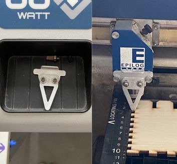 Focus tool: Put this tool at the bracket on the laserhead. Now
with the setting "Focus" selected, move op/down until the focus tool barely touches the
material
Focus tool: Put this tool at the bracket on the laserhead. Now
with the setting "Focus" selected, move op/down until the focus tool barely touches the
material 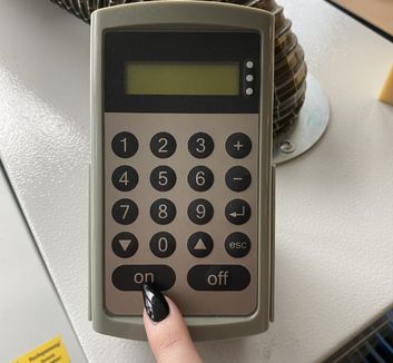 Air
filter: Needs to be truned on before cutting
Air
filter: Needs to be truned on before cutting 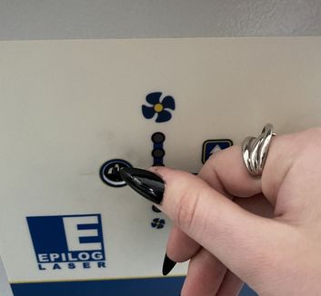 Compressor: Needs to be turnd on before cutting
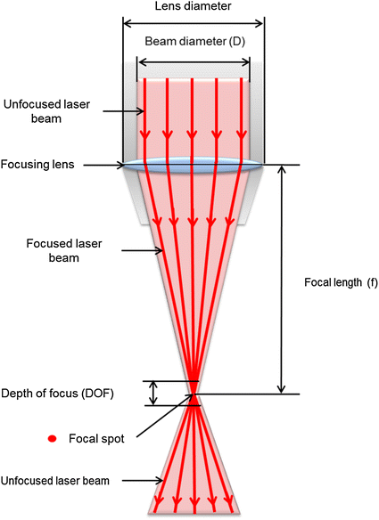
Characterization
Focus
The laser beam hits a mirror and is redirected through a lens. After hitting the lens, it will
form an hourglass-lik shape with the tightest
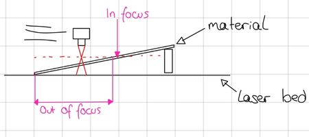
point being the focal spot. If you want thin and precise lines, your lasercutter should be set
to the height which will lead to the focal spot hitting your material.
How to characterize the focus (focal length):
 My instructor Ahmed showed me the following method:
 Putting
the
material inside
Putting
the
material inside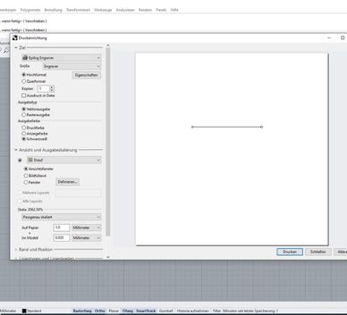 Preparing a line
file
Preparing a line
file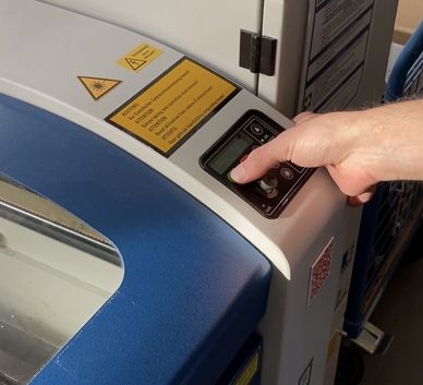 Setting up the
laeser (jog, focus, filter, compressor)
Setting up the
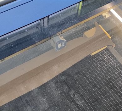
laeser (jog, focus, filter, compressor)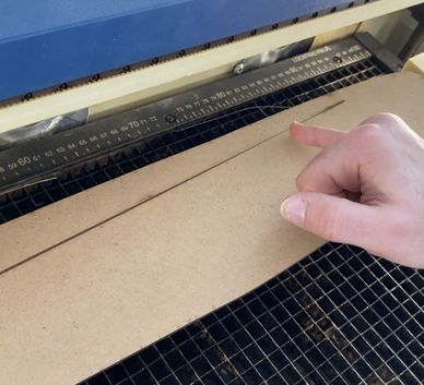 The cut line:
You can see the area where the line is the
thinnest
The cut line:
You can see the area where the line is the
thinnest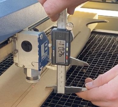 Measuring the
height difference: 42.01mm
Measuring the
height difference: 42.01mm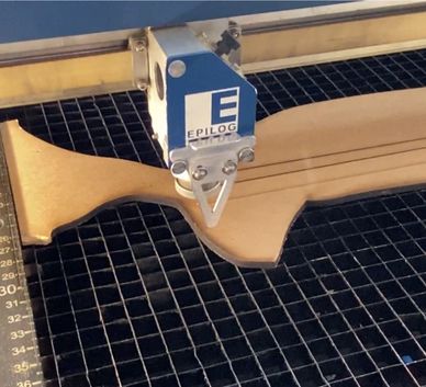 Now
taking the focus with the focus tool. It's actually not toching the material?
Now
taking the focus with the focus tool. It's actually not toching the material?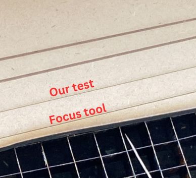 The line cut
with the focus tool is actually thicker, therefore the focus tool needs to be
recalibrated -> needs to be about 2mm longer
The line cut
with the focus tool is actually thicker, therefore the focus tool needs to be
recalibrated -> needs to be about 2mm longerPower & Speed
(Informations are taken from the lasers manual.)
In Vector mode:
Power: The power setting determines the amount of laser energy that is delivered to the
piece being cut and is adjustable in 1% increments from 0% to 100%. The higher the power, the
deeper the cut. The amount of power necessary to cut completely through a given material
is heavily dependent on the hardness and thickness of the material.
Speed: The speed setting determines the travel speed of the carriage (in Vector cutting
mode) and is adjustable in 1% increments from 1% to 100%. The slower the speed, the deeper
the cut. Most cutting applications require relatively slow speed settings, and the speed
is also heavily dependent on the material hardness and thickness. Slower speed settings will
produce better edge quality.
Additional parameters to note:
Speed Comp/Slow Cutting: Speed Comp reduces all speed settings by 1/2. Speed Comp mode will most often be used with speed settings below 10 when very slow cutting is desired.
Power Comp: Power Comp is especially useful for vector cutting jobs that include a large number of curves. Power Comp reduces the laser output when the lens carriage slows as it moves through a curve.
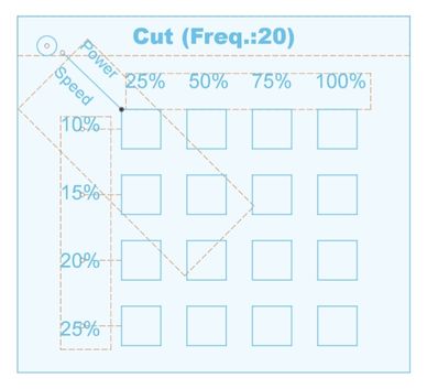
I created a PowerxSpeed matrix for cutting MDF 3mm (to use different types of settings in one cut, you need to use colormapping in the software, how to do this is shown further down):
 The design in
Fusion:
The design in
Fusion: 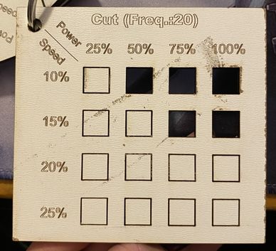 The cut file:
Cut matrix with given frequency of 20% (as recommended by the manual).
Optimal settings
for cutting MDF 3mm: ~ S:15% P:85% | For marking: ~ S:85% P:15%
Power: The power setting determines the amount of laser energy that is delivered to the piece being cut and is adjustable in 1% increments from 0% to 100%. The higher the power, the deeper the engraving.
Speed: The speed setting determines the travel speed of the carriage and is adjustable in 1% increments from 1% to 100%. The slower the speed, the deeper the engraving. The speed is also heavily dependent on the material hardness and thickness. Harder materials require slower speed for deeper engraving. Slower speed settings will produce greater depth of engraving.
I created a PowerxSpeed matrix for engraving MDF 3mm:
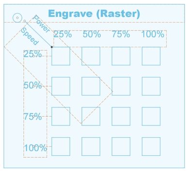 The design in
Fusion:
The design in
Fusion: 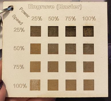 The cut file:
There isn't one optimal setting for engraving, it really depends on what outcome you wish for. Choose a slow speed setting of 25%-50% for darker and deeper cuts, and above for thinner and lighter cuts.
Frequency
The Frequency is the number of laser pulses that the laser fires per inch of travel and can be
adjusted from 1 to 100. A lower frequency number will have the effect of less heat, because fewer
pulses are being used to cut the material. Lower frequency rates are helpful on material like wood
where charring is evident at higher frequencies. High frequencie are useful on material like acrylic
where a large amount of heat is desirable to melt, or flame polish the edge. (Very low frequencies
from 1 to 5 will might produce a perforation, not a continuous cut.)
I created another matrix for the optimal cut and mark settings with different
frequencies:
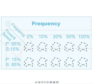 The design in Fusion:
 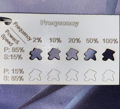 The cut file:
Kerf
The kerf refers to the width of the cut made by a laser beam during the lasercutting process.
Essentially,
it is the material that is removed by the laser as it cuts through the material.
Kerf width can vary depending on the type and power of the laser, as well as the material being cut.
Kerf width is an important consideration in lasercutting because it affects the precision and
accuracy of the cuts, especially when cutting pressfit joints.
If the kerf is too wide, it can result in a loss of detail and accuracy in the finished product.
Therefore, understanding and controlling kerf width is crucial for achieving the desired level of
precision and accuracy in lasercutting projects.
In Fusion the slots were designed to be from 1mm to 3mm. Each of the slots was about 0.2mm wider
after actually being lasercut.
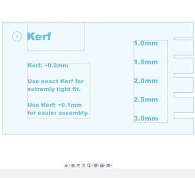 The design in Fusion:
 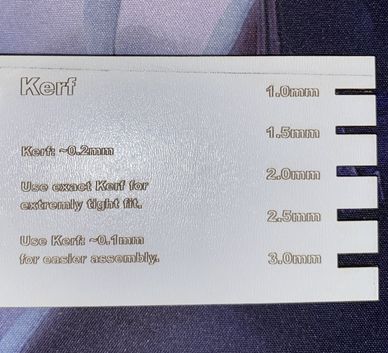 The cut file:
Joint-types & -clearance
Joint types refer to the different ways two pieces of material can be joined together after being
laser cut, such as finger joints or slotting joints.
Joint clearance is directly related to the kerf and describes the distance between the two pieces of
material being joined. This is important
to consider when laser cutting because it affects the quality and strength of the joint.
I cut several joint types with and without kerf to show the clearance:
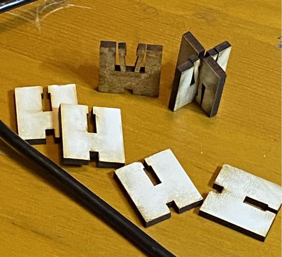
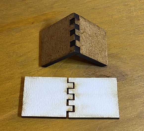 Finger-joints: These illustrate joint clearance the best, the upper
one was cut with kerf and the one below without. Without kerf in mind, the joints don't hold
together at all, but with it's a strong fit.
Finger-joints: These illustrate joint clearance the best, the upper
one was cut with kerf and the one below without. Without kerf in mind, the joints don't hold
together at all, but with it's a strong fit.
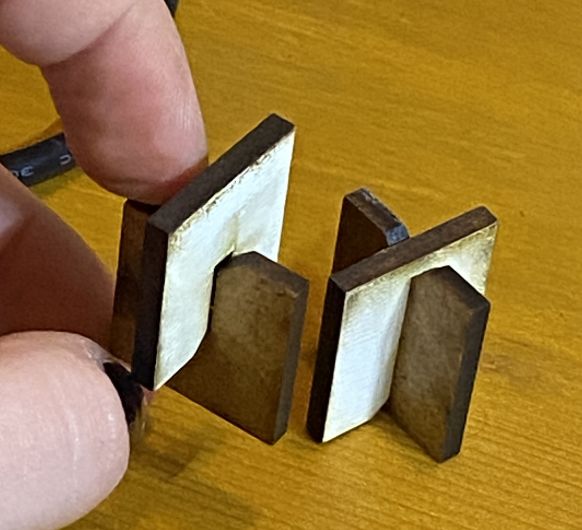 Press-fit
joints: Right with, left without. Both fit together quite
well, the one right needed a hammer to assemble, the one left can be adjusted easily with
fingers.
Press-fit
joints: Right with, left without. Both fit together quite
well, the one right needed a hammer to assemble, the one left can be adjusted easily with
fingers.
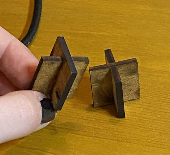 Chamfer
press-fit joints: Same as the regular. The chamfer made it a lot easier to assemble
than with the regular press fit.
Chamfer
press-fit joints: Same as the regular. The chamfer made it a lot easier to assemble
than with the regular press fit.
 Snap fit and flexture joints: Both did not work, as this wood was not bendable
enough. The parts either broke or did not fit at all.
Snap fit and flexture joints: Both did not work, as this wood was not bendable
enough. The parts either broke or did not fit at all.
End of group assignment
Laser-cutting
In this week it was very important to have a parametric design which also could be assembled
multiple ways. Since I like creating things that have a practical use for me, I decided to
create an iPad stand with a holder for my ApplePencil. The pencil holder can be placed on every
side of the stand to fulfill the criteria of multiple assembly options (probably a gray area,
but still :D).
This is the tutorial I followed for the basics of the stand: https://www.youtube.com/watch?v=7riGolu7BpA
.jpg) First, I created a new component called "Leg". I modeled the vague form of the leg with lines
and constrained + dimensioned the lines later on (also using parameters).
First, I created a new component called "Leg". I modeled the vague form of the leg with lines
and constrained + dimensioned the lines later on (also using parameters).
.jpg) After finishing this and adding a few fillets, I copy and pasted the leg, so that the new leg
would always look like its original.
After finishing this and adding a few fillets, I copy and pasted the leg, so that the new leg
would always look like its original.
.jpg) Then I modeled the main plate which would hold the iPad and created the needed joints for it to
fit with the legs.
Then I modeled the main plate which would hold the iPad and created the needed joints for it to
fit with the legs.
.jpg) Since this would be a very wobbly construction I added supports.
Since this would be a very wobbly construction I added supports.
.jpg) I started modeling the pencil holder afterward and I made sure it could be placed on both sides
of the stand.
I started modeling the pencil holder afterward and I made sure it could be placed on both sides
of the stand.
.jpg) The final stand!
The final stand!
.jpg)
Here you can see the parameters I used:
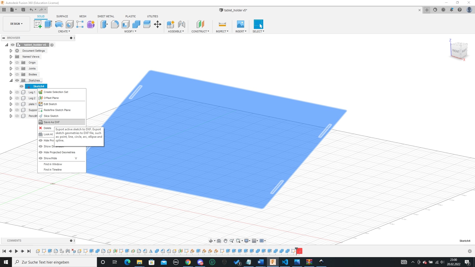
I then created my dxf files from this 3d model. To do so, I created a sketch on top of each
of the objects faces that I needed. I used the offset option to add the kerf in the needed
areas. Then I exported it as dxf.
.jpg)
Now it was finally time to cut the design! (The details about the cutting process can be found on the group assignment page)
.jpg) I tried to waste as little material as possible.
I tried to waste as little material as possible.
.jpg) The stand assembled in one way (pencil holder on right side)
The stand assembled in one way (pencil holder on right side)
.jpg) The stand assembled in the other way (pencil holder on left side)
The stand assembled in the other way (pencil holder on left side)
Parametric box
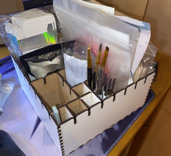
Since this is my second year doing FabAcademy I also have a project for 2023. I wanted to design a box to organize my desk, which I could assemble to have different sized compartments.
 I
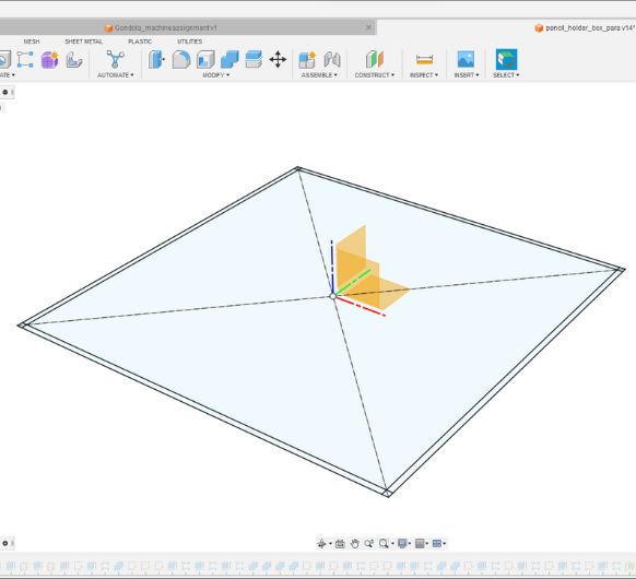
created a sketch for the ground and the walls.
I
created a sketch for the ground and the walls.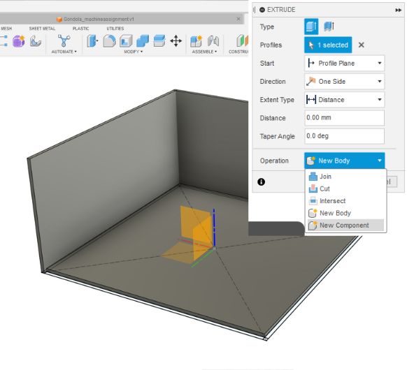 Then I continued to extrude the ground and walls out of it, please note that every new
extruded object has to be a seperate "component". This is important later, when you want to
lay all parts flat.
Then I continued to extrude the ground and walls out of it, please note that every new
extruded object has to be a seperate "component". This is important later, when you want to
lay all parts flat.
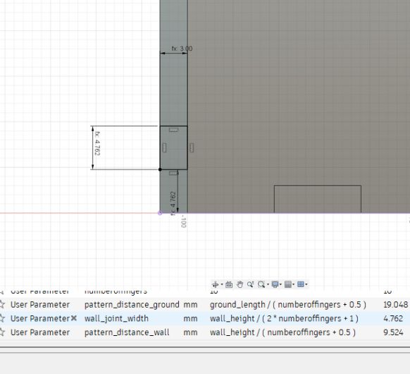
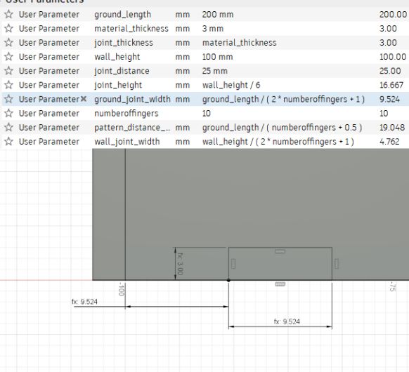 I created a new sketch on one of the walls to create the fingerjoints. I'm only doing one
for now, as the rest will be done with a rectangular pattern. You can also see the formula
that determines the length of the fingerjoints. With this formula the joint size is always
adjusted to the material thickness and the length over which you want to distribute them.
I created a new sketch on one of the walls to create the fingerjoints. I'm only doing one
for now, as the rest will be done with a rectangular pattern. You can also see the formula
that determines the length of the fingerjoints. With this formula the joint size is always
adjusted to the material thickness and the length over which you want to distribute them.
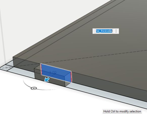 I extruded this joint.
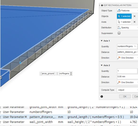 Using a rectangular pattern with the object type set to "Features". I'm then choosing the
"Extrude" from before as the feature to create many joints. You can also see the parameters
I used for this.
I'm repeating this process for the remainign three walls.
Using a rectangular pattern with the object type set to "Features". I'm then choosing the
"Extrude" from before as the feature to create many joints. You can also see the parameters
I used for this.
I'm repeating this process for the remainign three walls.
 Repeating this concept for the joints of the walls as well.
 Done for all walls.
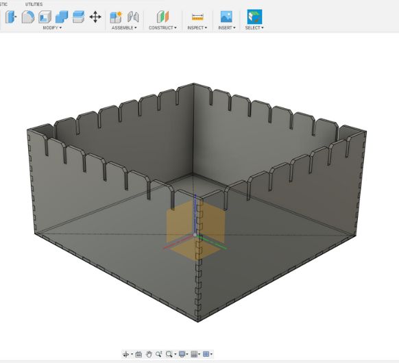
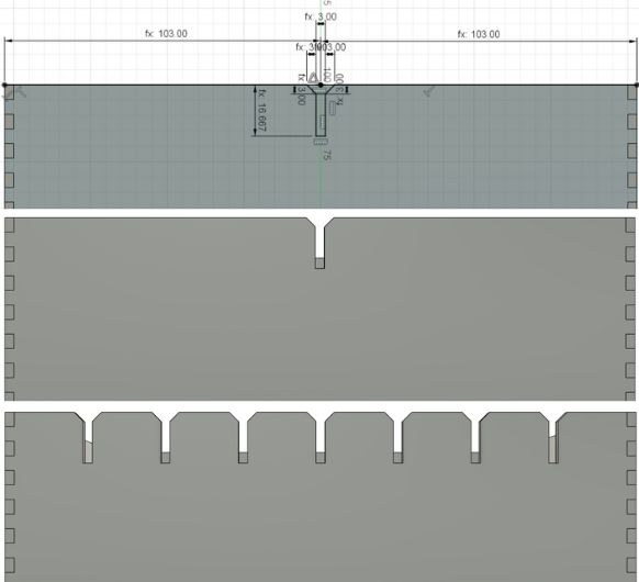 Now I start with the "crown"-like pattern. This will function as the part where you can put
the walls to freely assemble the compartments of the box.
Now I start with the "crown"-like pattern. This will function as the part where you can put
the walls to freely assemble the compartments of the box.
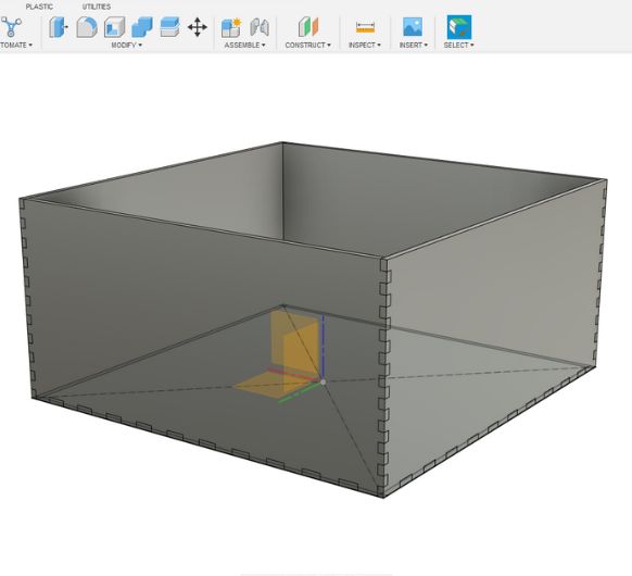
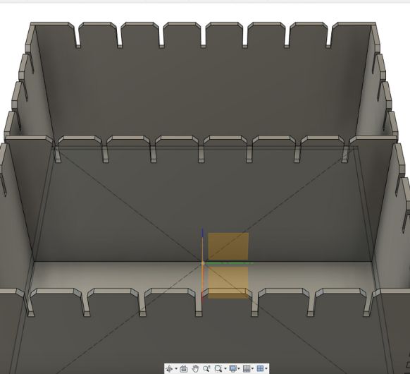
 Done for all 4 walls.
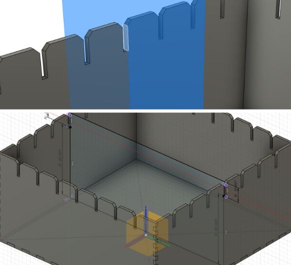 Creating a construction plane to sketch the compartment walls on in the middle of the box.
 Repeating the same crown-pattern concept on the compartment walls.
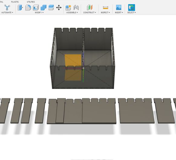 It was tiresome to do this whole process for every type of compartment I needed, so I used
Copy+Paste to duplicate the compartments and then I simply split them into the size I
needed.
It was tiresome to do this whole process for every type of compartment I needed, so I used
Copy+Paste to duplicate the compartments and then I simply split them into the size I
needed.
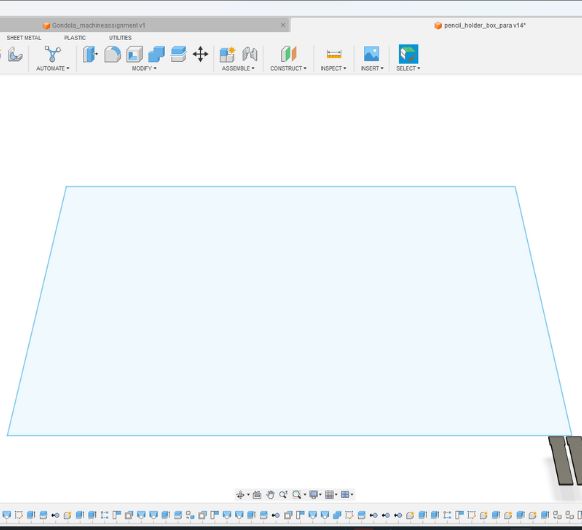 Here I created a rectangle the size of the lasercutter work area.
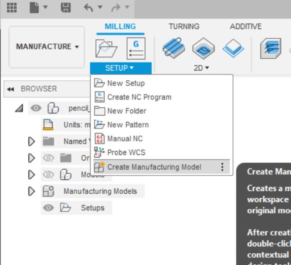 With all of this I went into the Manufacture workspace and created a new manufacturing
model. You can edit manufcturing models without the ordiginal design being affected in any
way.
With all of this I went into the Manufacture workspace and created a new manufacturing
model. You can edit manufcturing models without the ordiginal design being affected in any
way.
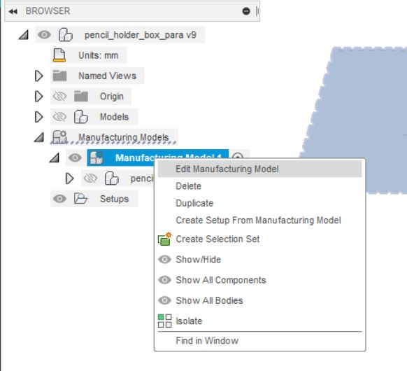 Talking about editing it, it's time to do so now, right click on the model to edit.
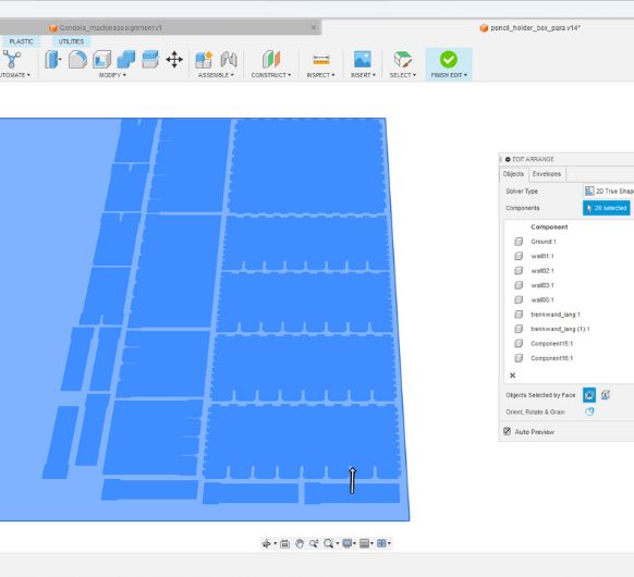 And arrange.
 If you haven't done so yet, use the offset tool to account for the kerf.
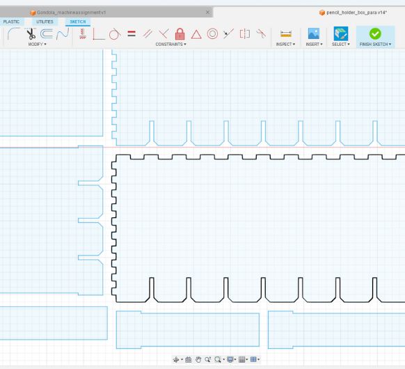
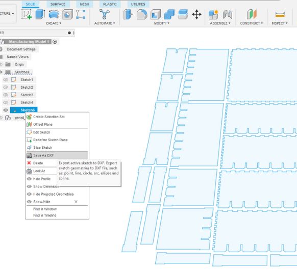 Right click on the sketch and Save as DXF. Save the file on a usb stick and go the laser
cutter! :)
Right click on the sketch and Save as DXF. Save the file on a usb stick and go the laser
cutter! :)
To use the laser cut, refer to the steps above as shown in the group assignment. After everything is cut you can assemble this box in any way you like:
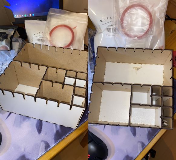 I decided to arrange the compartments like this. But if I need to, I can make them smaller by adding more walls or bigger by removing them.
Vinyl-cutting
How I used the vinyl cutter:
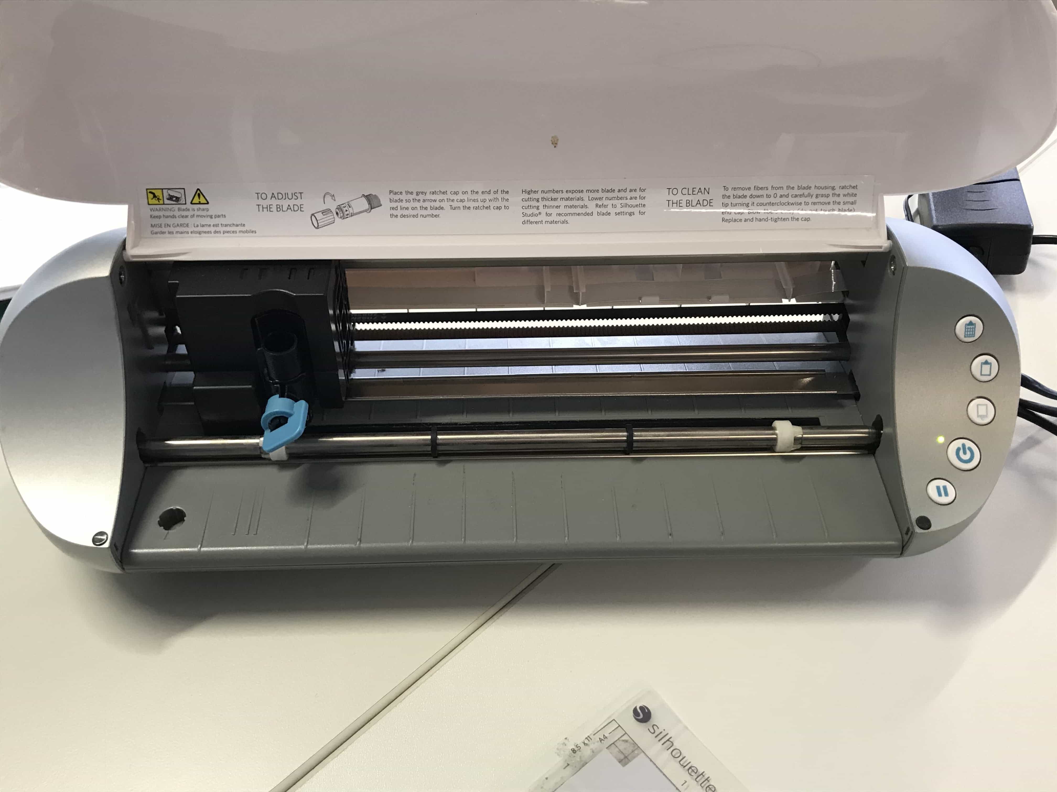
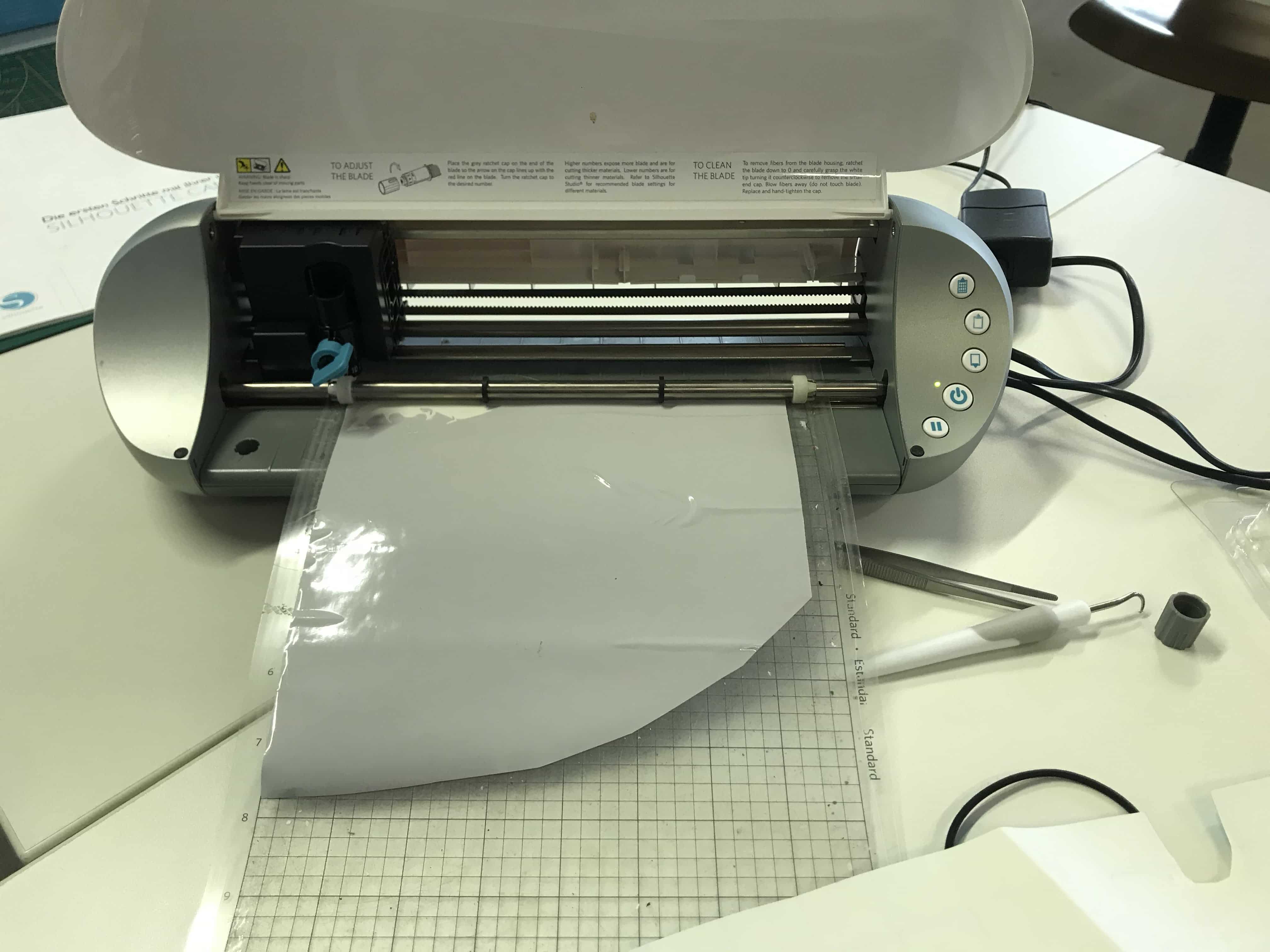
- Assemble and connect the vinyl-cutter (silhouette cameo)
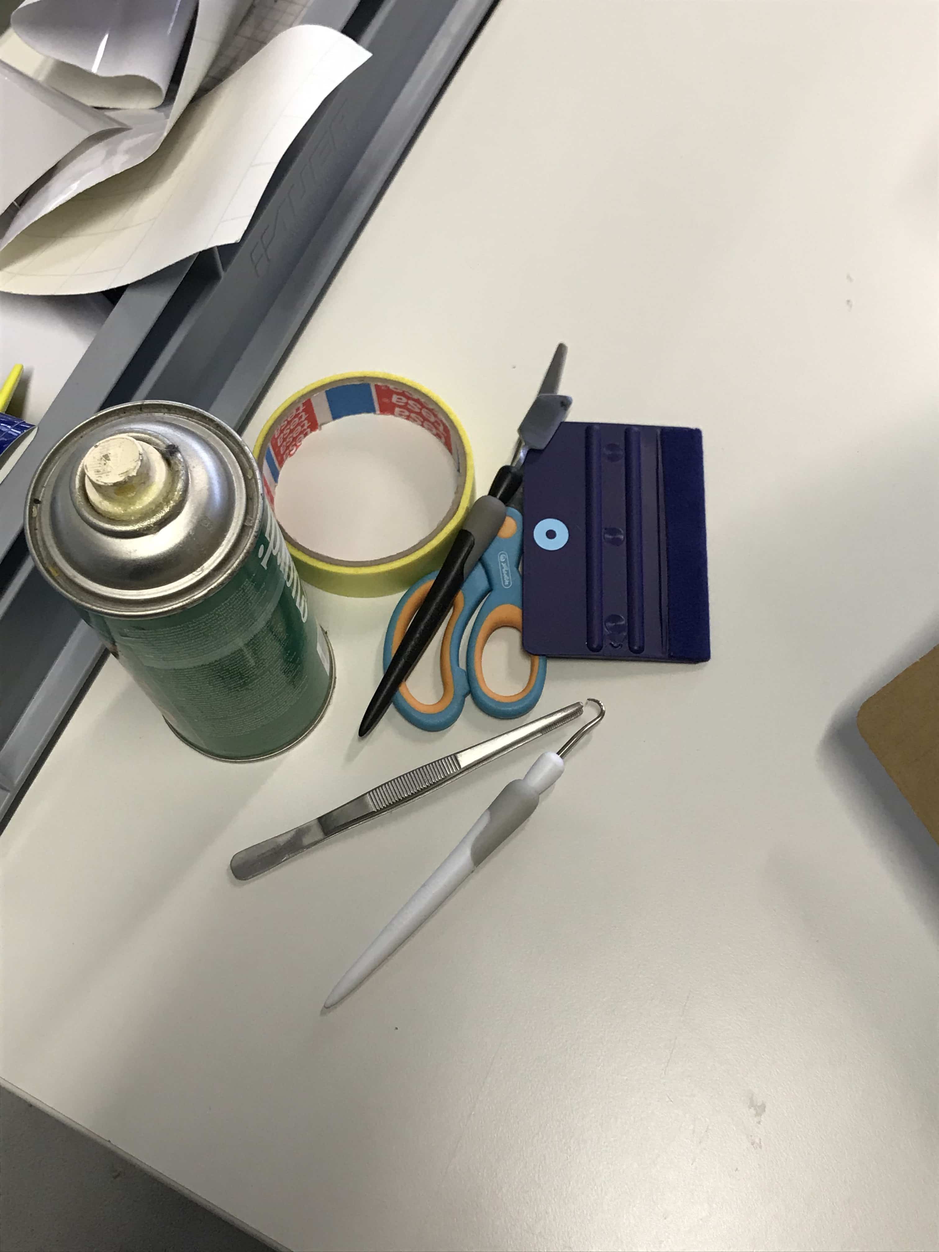
- Get some tools you might need (e.g. adhesive spray, tape, tweezers):
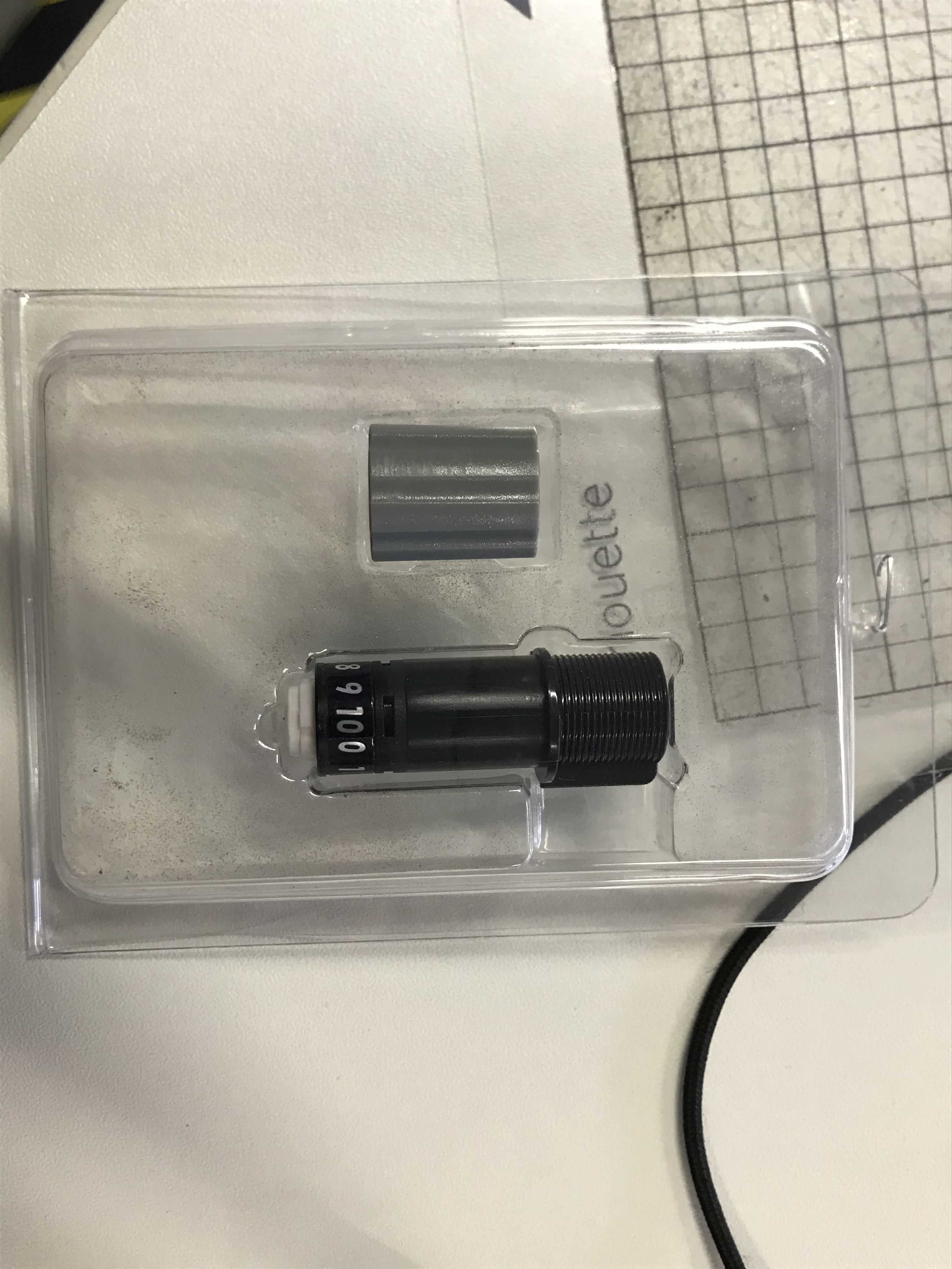
- Adjust the blade (black) with the grey tool
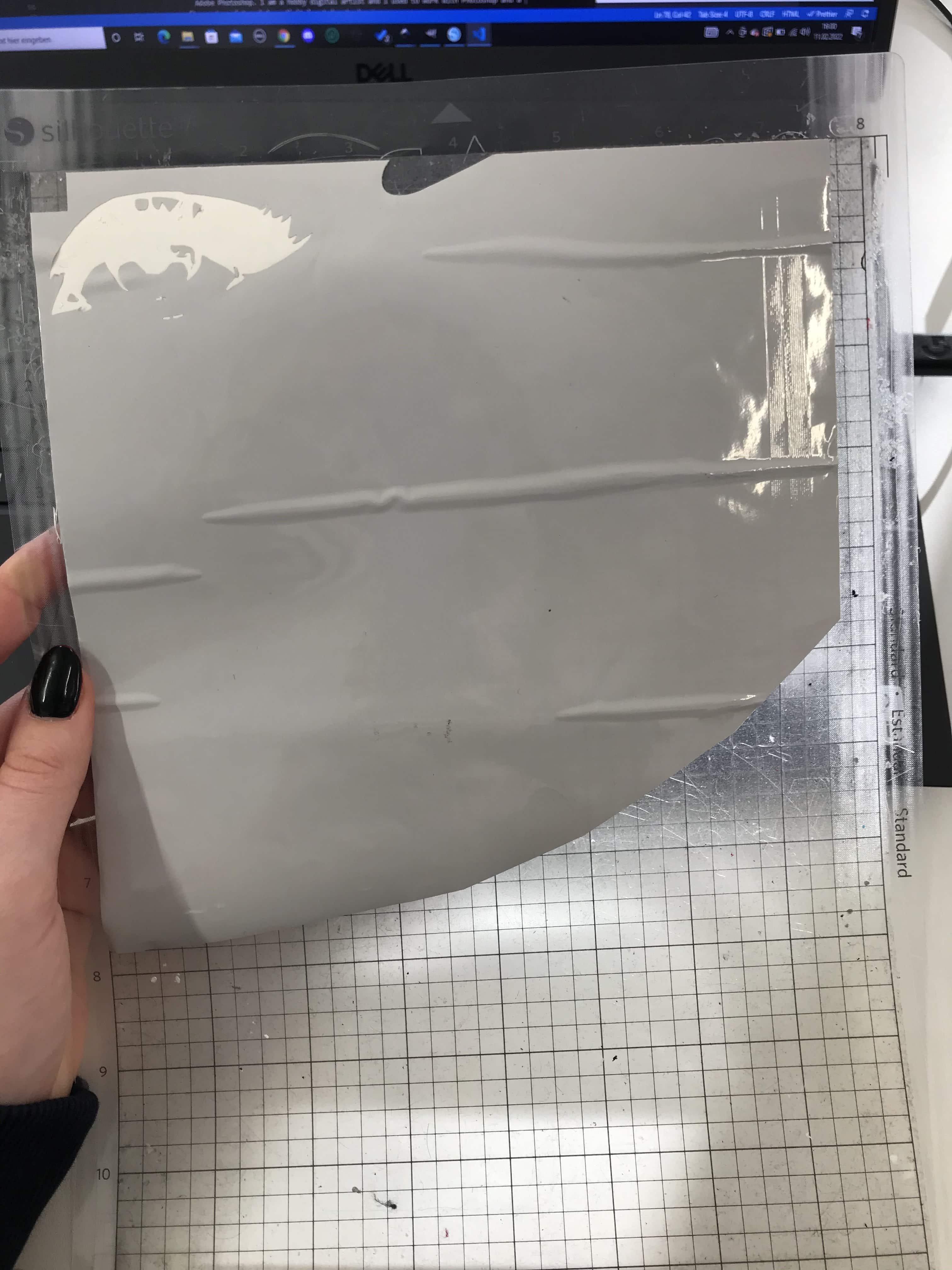
- Prepare the material (stick to the adhesive plate). There are different types of material: Sticker material and heat transfer material for clothing. I chose sticker material:
- Insert the plate into the vinyl-cutter (use buttons on the right)
- Prepare the file.
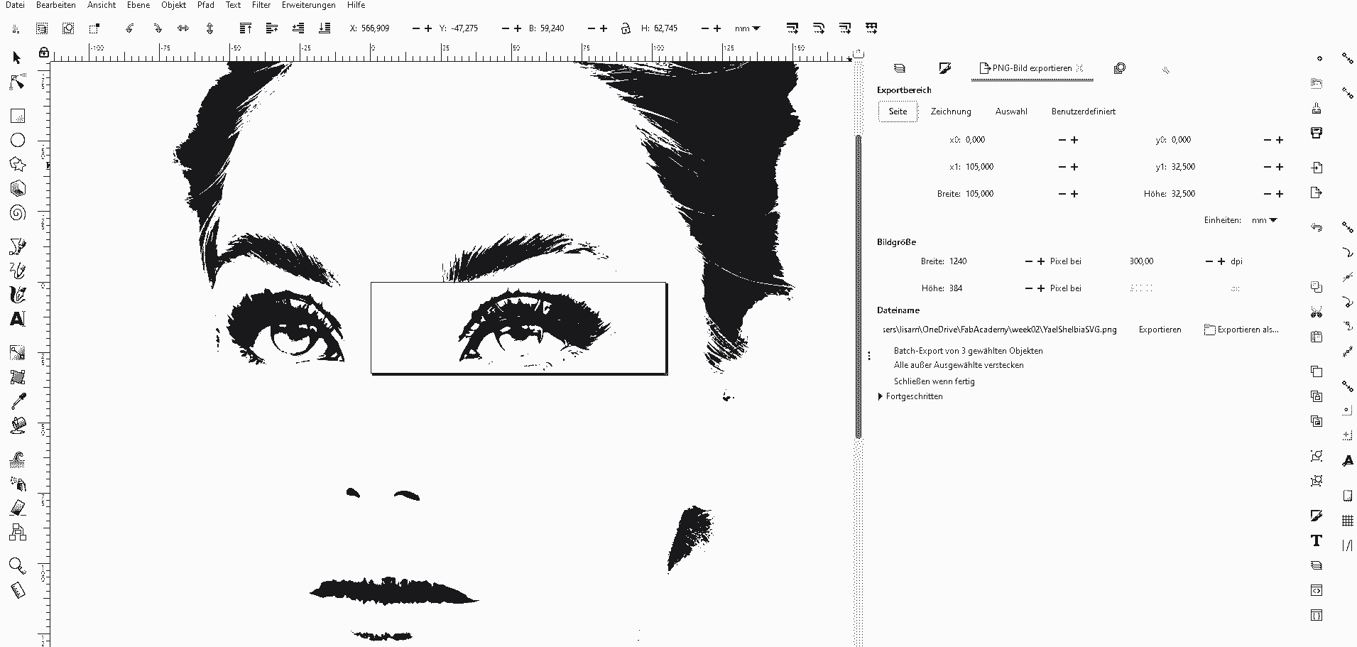
- I reused the svg file from last week:
- I only took the eye though, because the whole head was too complicated
- I exported just the eye as an svg in inkscape
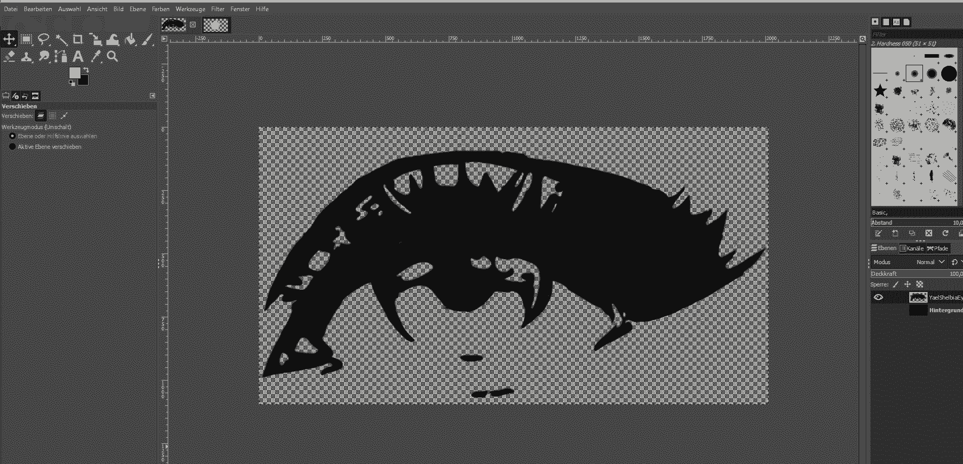
- I opened this file in Gimp and simplified the edges / clearded them up to rid them of details
- I exported the file as png
- I imported the file in Inkscape and traced the bitmap of it to get an svg again:
- Select the image and go to Path>Trace Bitmap
- Adjust the settings to you liking (you have a preview that you can update)
- Hit OK and the vectorised art will pop up ontop of you raster image
- I exported it as a dxf file from inkscape
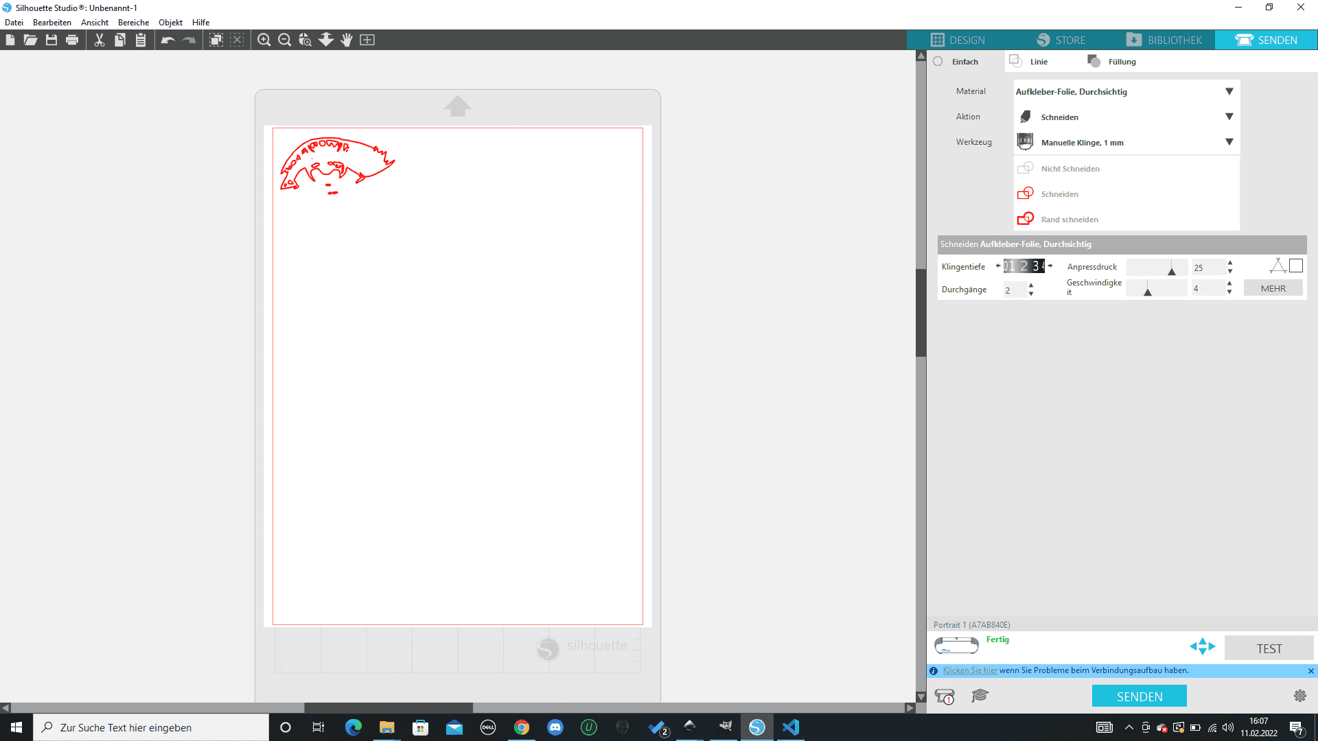
- I opened silhouette studio and imported the dxf file
- I adjusted the position and settings
- Hit "Send"
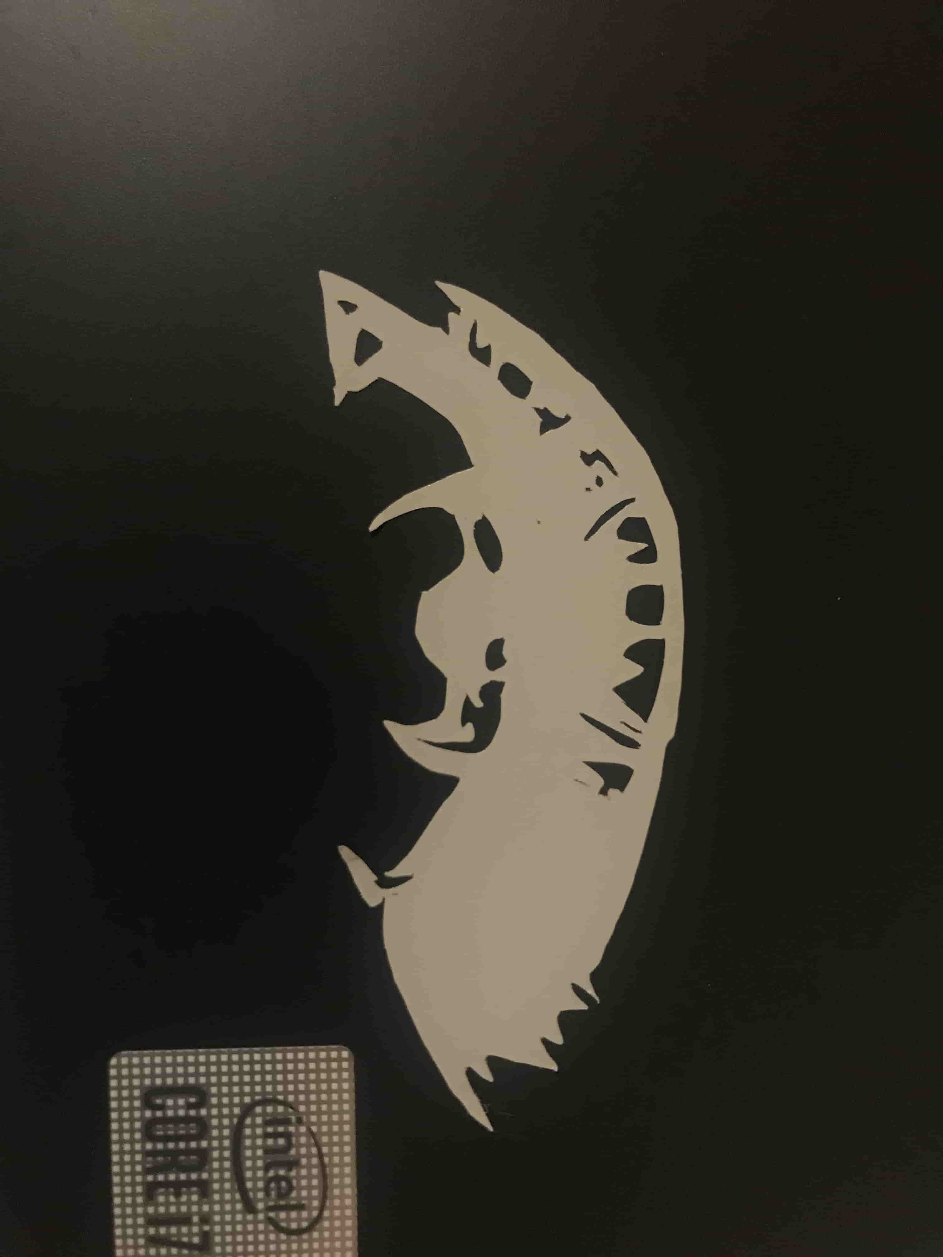 The sticker I put on my laptop!