Group assignment by Lisa Schilling and Jan Bewersdorff for Lasercutting
Characterize your lasercutter's focus, power, speed, rate, kerf, and joint clearance
Document your work to the group work page and reflect on your individual page what you learned
Link to the group assignment page
Since our FabLab consists of two locations, this assignment has to be made twice. Once for Kleeve
and
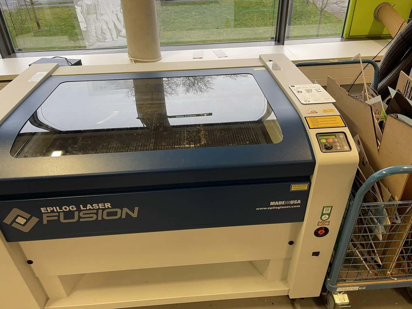
once for Kamp-Lintfort. The Laser cutter we used at the FabLab in Kamp Lintfort was the Epilog
Fusion.
The goal of this weeks group assignment was to learn more about the laser cutter at our local FabLab and to characterize it's properties.
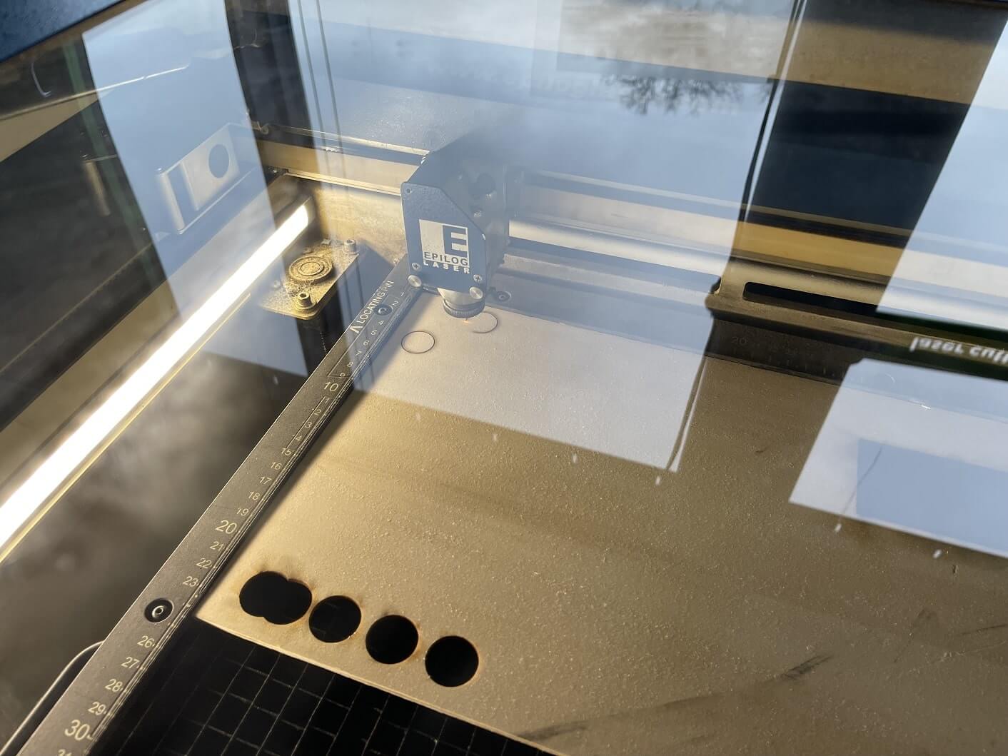
In the FabLab in Kamp-Lintfort (Germany) we mainly use the Epilog Laser Fusion (60 Watts):
The Epilog Fusion at the Lab
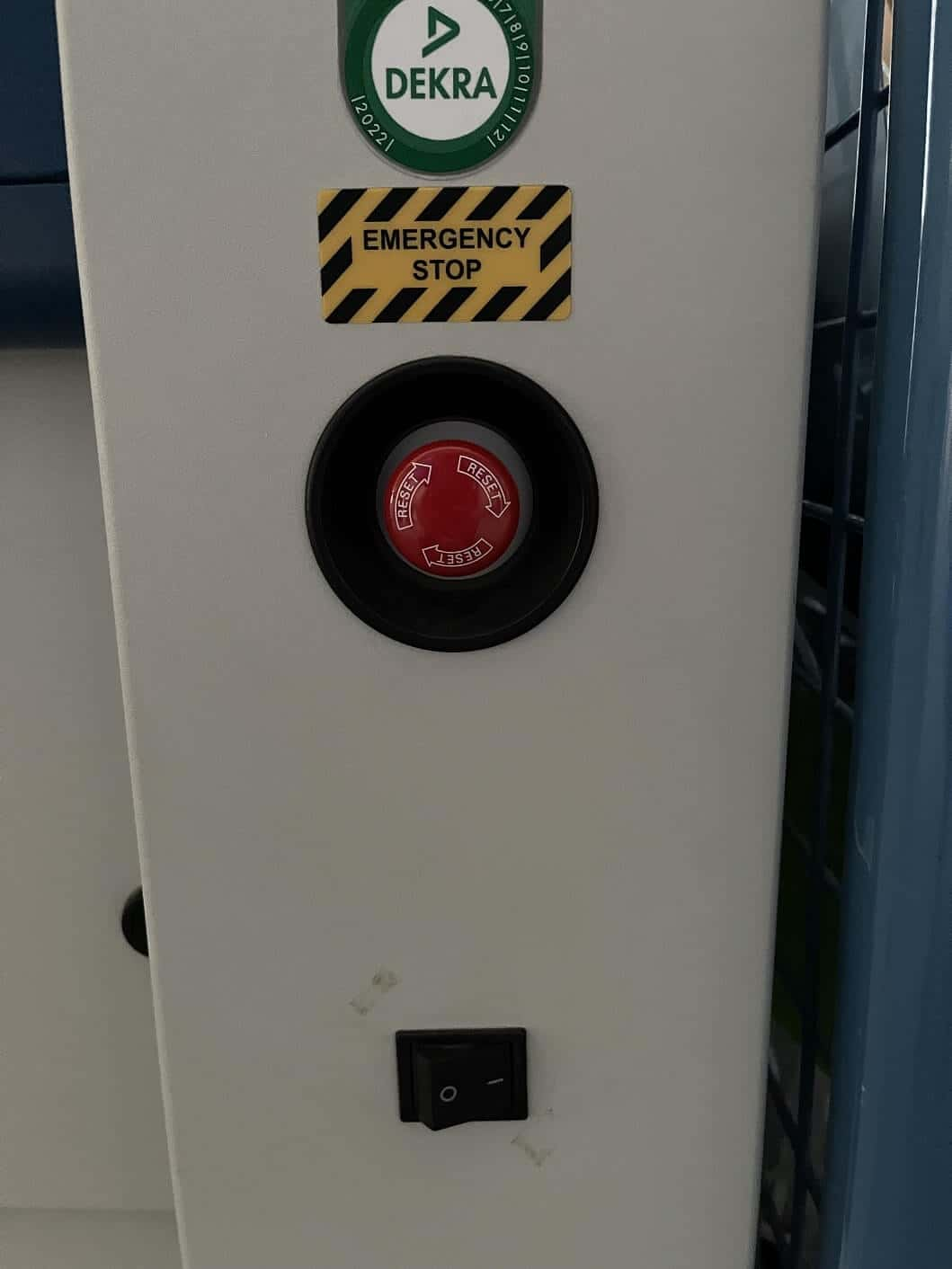
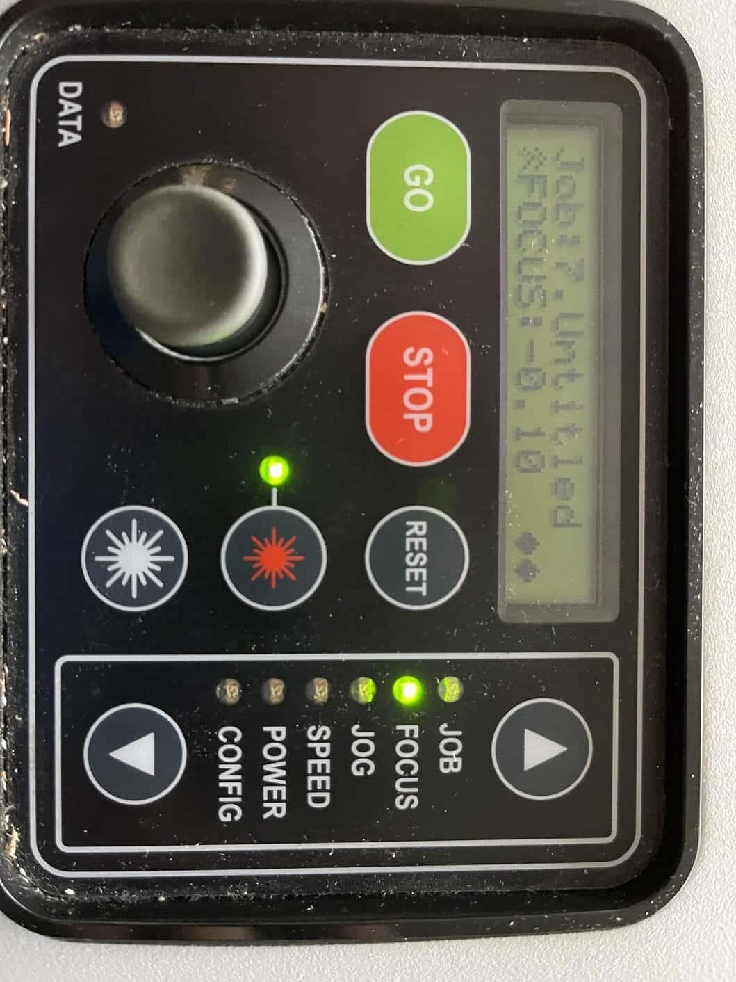
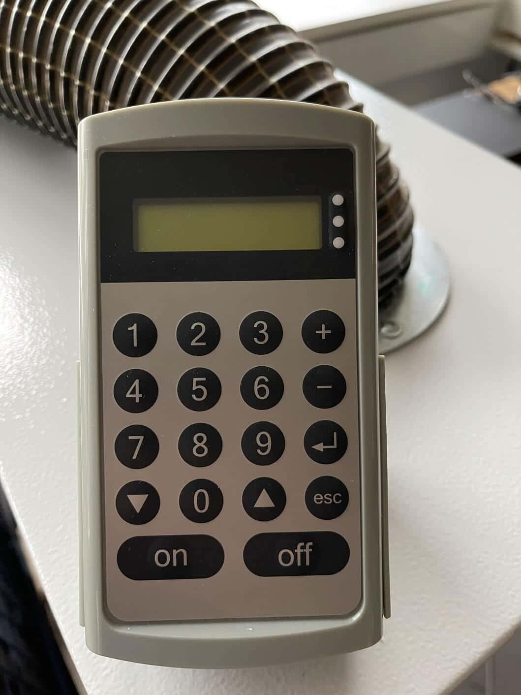
In order to run the Lasercutter it first has to be turned on. After that you can change settings and
set the focus via the control panel of the machine:
The E-Stop and the power buttonThe control panel of the machine
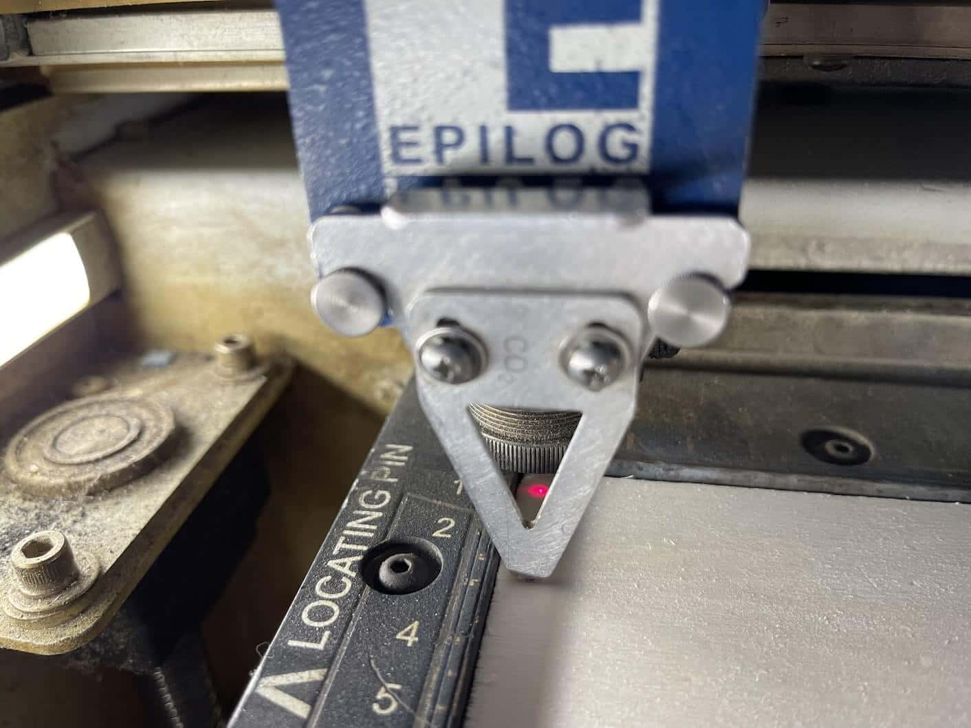
In order to set the focus correctly, the machine has a small triangular part that can be set onto
the laserhead. This part should barely touch the material you want to cut. In order to adjust the
beds position for focusing you just need to select the focus setting and after that can move the bed
with the joystick.
The focus tool attached to the laser head
After setting the focus you can also "jog" the head itself to set a new home position for the head.
This makes it easier to cut pieces from material that has been cut before. Before cutting you have
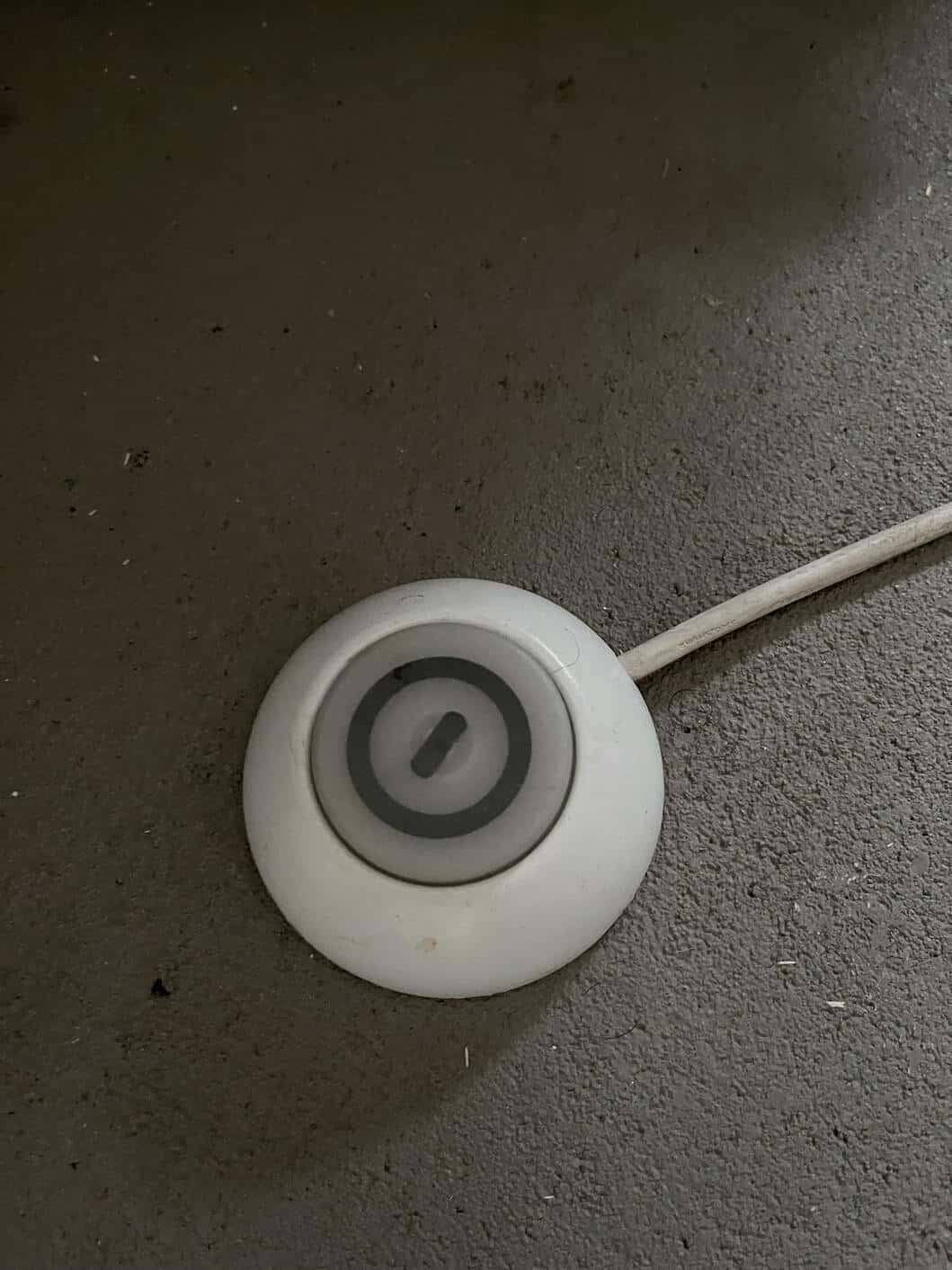
to start the air filter and the compressor. In our case this is done via these two buttons:
Press "On" on this panel and the air filter startsThis Footbutton starts the compressor
After waiting a short amount of time we could start cutting. We started with a few test cuts to
check the lasers possibilities:
The first few test cuts
Together with Ahmed we tried out multiple cuts. This is were Ahmed was surprised that the lasers'
power
was so weak. To check out what was wrong, we disassembled and cleaned the Lasercutter. In this
process
Ahmed also took a look at the lens of the laser cutters' head. It was very tinted and dirty,
possibly
resulting in the low power of the laser.
Laser Cutter Characterization
Focus
The epilog laser fusion usually has autofocus. When using color mapping, the focus can be changed during the cutting process. The focus can be incremented in units of 100 or 10. Each unit of 100 is equal to 0.1 inch (216mm). Each unit of 10 is equal o 0.01 inch (.254mm). The focus slider has a range of -500 to +3000. A positive number means the table is being moved away from the focus lens. In other words, a positive number indicates, that the gap between the table and the focus lens is getting greater (positive = increasing).
Any time the focus setting is a negative number, the gap between the table and the focus lens is getting smaller (negative = decreasing).
The table can be as close as 0.5 inch (-500) or as far as 3 inches (3000).
Power, Speed and Frequency
(Informations are taken from the lasers manual.)
In Vector mode:
Power: The power setting determines the amount of laser energy that is delivered to the piece being cut and is adjustable in 1% increments from 0% to 100%. The higher the power, the deeper the cut. The amount of power necessary to cut completely through a given material is heavily dependent on the hardness and thickness of the material.
Speed: The speed setting determines the travel speed of the carriage (in Vector cutting mode) and is adjustable in 1% increments from 1% to 100%. The slower the speed, the deeper the cut. Most cutting applications require relatively slow speed settings, and the speed is also heavily dependent on the material hardness and thickness. Slower speed ettings will produce better edge quality.
Frequency: The Frequency is the number of laser pulses that the laser fires per inch of travel and can be adjusted from 1 to 100. A lower frequency number will have the effect of less heat, because fewer pulses are being used to cut the material. Lower frequency rates are helpful on material like wood where charring is evident at higher frequencies. High frequencie are useful on material like acrylic where a large amount of heat is desirable to melt, or flame polish the edge. (Very low frequencies from 1 to 5 will produce a perforation, not a continuous cut.)
In addition to speed, power and frequency, there are two additional parameters for vector mode:
Speed Comp/Slow Cutting: Speed Comp reduces all speed settings by 1/2. Speed Comp mode will mot ofte be used with peed settings below 10 when very slow cutting is desired.
Power Comp: Power Comp is especially useful for vector cutting jobs that include a large number of curves. Power Comp reduces the laser output when the lens carriage slows as it moves through a curve.
In Raster mode:
Power: The power setting determines the amount of laser energy that is delivered to the piece being cut and is adjustable in 1% increments from 0% to 100%. The higher the power, the deeper the engraving.
Speed: The speed setting determines the travel speed of the carriage and is adjustable in 1% increments from 1% to 100%. The slower the speed, the deeper the engraving. The speed is also heavily dependent on the material hardness and thickness. Harder materials require slower speed for deeper engraving. Slower speed settings will produce greater depth of engraving.
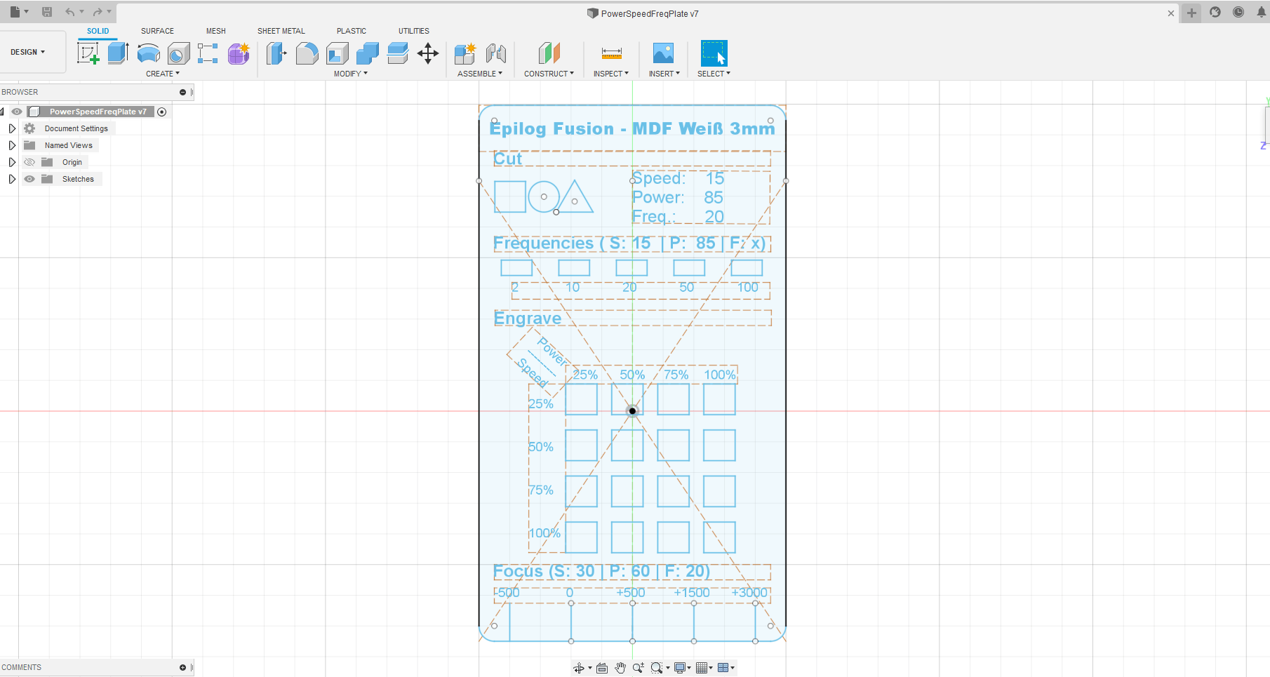
To determine these parameters (power, speed, frequency & focus) for a material, I designed a template showing different settings for different parameters and their outcomes. This was inspired by already existing templates of that kind in our FabLab. But most of these templates were for other lasercutters.
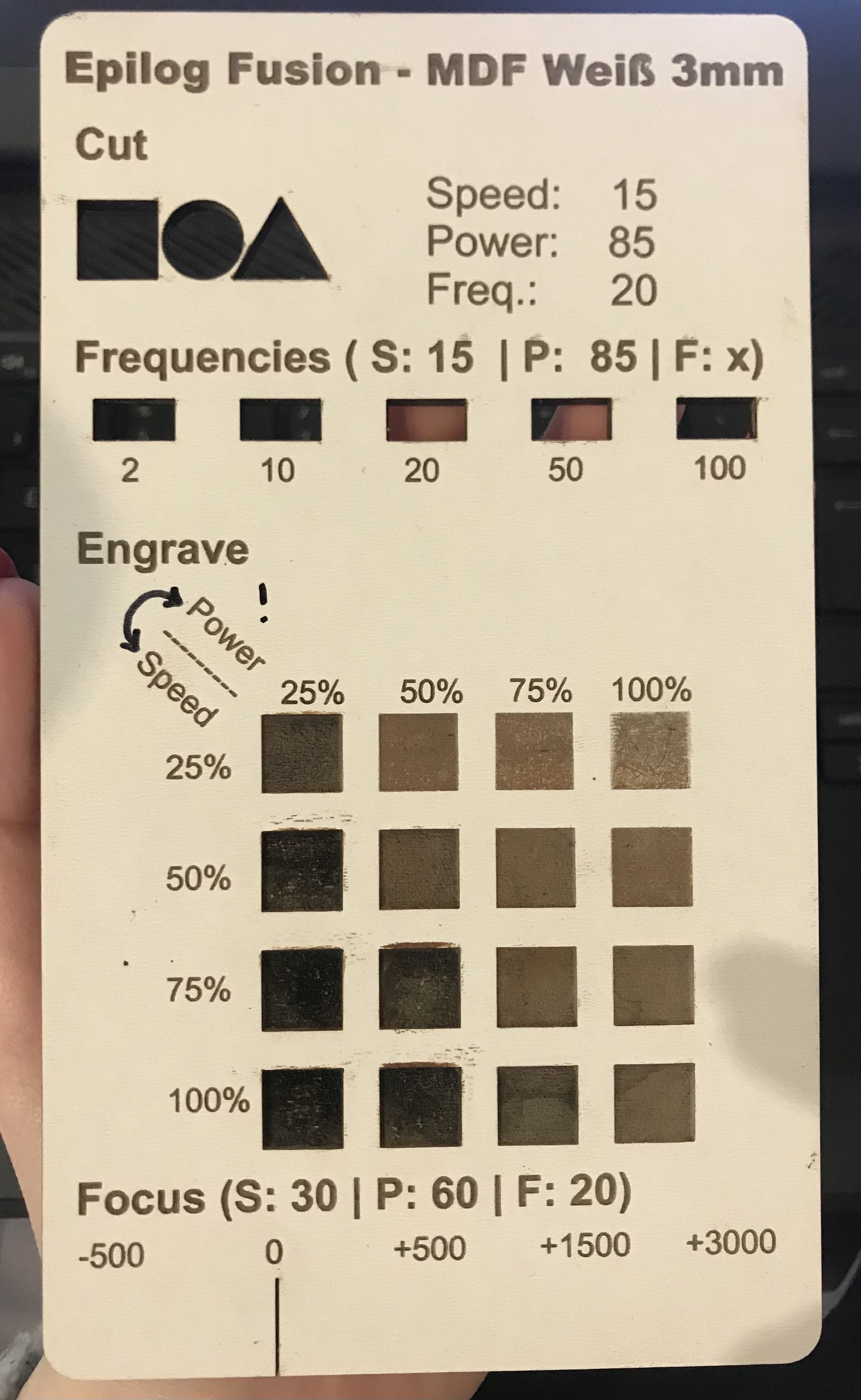
The designed plate in Fusion has areas for "Cut", "Frequency", "Engrave" and "Focus". The settings for "Cut" were determined by some tests I did beforehand:
I exported the design as .dxf from Fusion and imported it in Rhinoceros to prepare it for cutting. I had to remove some of the former contruction lines, because they got exported as well.
To make the text engraveable I needed to hatch it: Dimension>Hatch>Select the text .
To cut the plate with the least amount of jobs I had to use color mapping (lots and lots of color mapping):
Everything that was to be cut had it's own settings, as well as all of the engravings. You can set all of the colors in the Color Mapping tool and then go back to your file to change the colors of the corresponding objects accordingly.
This took quite long, but as soon as I was done I was able to cut the plate:
The general cutting with the usual settings (15/85/20) went very well. The engraved texts (50/75/50) also came out nicely.
Varying the frequency did not make a big difference when cutting with the usual settings (15/85/x). The only noticable effect it had, was that the first few cuts with the low frequency were slighty harder to remove.
I made a small mistake in the "Engrave" area, as I switched "Power" and "Speed" on the x and y-axis. Other than that, the engraving worked very well and did a great job at visualizing the effect of the different settings.
In the last area, the "Focus" area, I intended to make multiple cuts with different settings, that would not fully cut through the plate (30/60/20) and choose a different focus for each cut to show it's effect. The lasers manual stated, that there was an option to change the focus during the cutting process via color mapping, but I could not find the slider to change the focus in the color mapping tool.
To make up for this at least a bit, I cut one of the lines. When comparing the top and the bottom of the plate, you can still see a big difference in the thickness of the line, indicating how the laser beam cuts through the wood:
Kerf
During the lecture Rico mentioned a website one of his students once made, which would create SVGs to
test and measure the kerf of laser cutters. We found the website very intuitive and used it to
create
the following SVG:
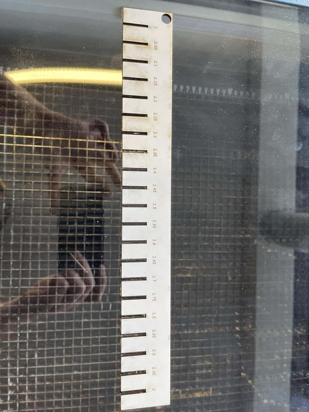
The svg to check the kerf of the laser cutter
After testing out cuts by playing around with the settings, I cut the SVG from above leaving me with
this laser cut part:
The lasercut kerf tool
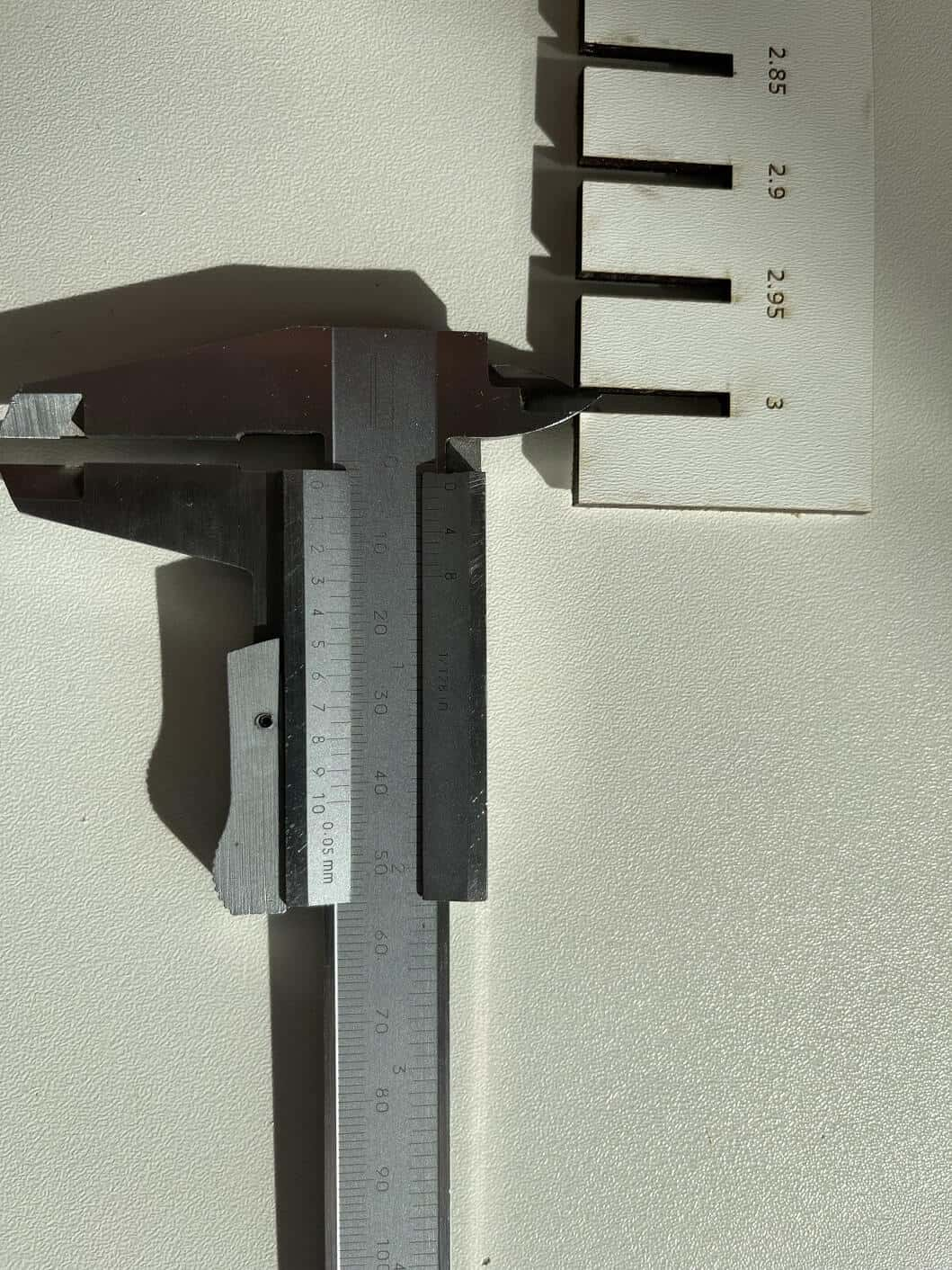
In order to calculated the Kerf, we used callipers and measured the real distance the lasercutter
cut:
Measuring the real distance that was cut
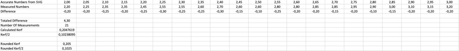
After measuring everything we wrote all numbers into an excel sheet and calculated the kerf of of
that:
Calculation of the kerf
As can be seen in the picture the measured kerf was (rounded) 0.205mm resulting in a needed offset
of 0.1025mm for lasercutting parts.
Joint Clearance and Types
In order to check the Joint Clearance for all the different types, we recreated different Joint
types
shown to us in the lecture in Fusion360. Each Joint type was created twice. Once not using the kerf
to
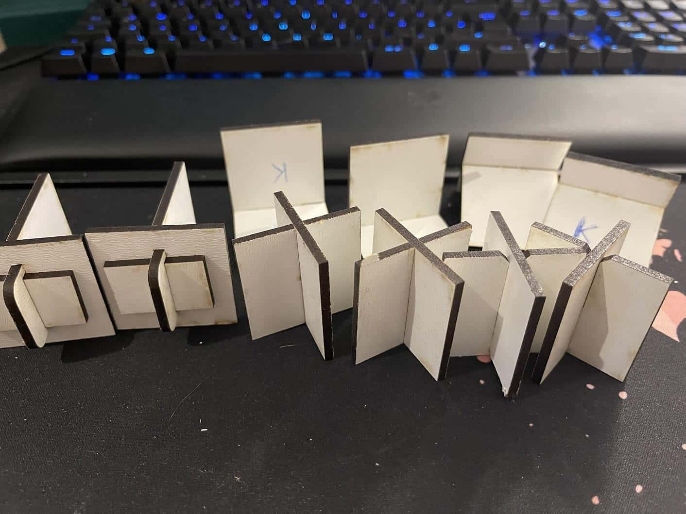
adjust the cut and once using the kerf. The Fusion360 File can be downloaded here. After cutting the different
Joint types we were left with the following pieces:
The different types of Joints we cut using and not using kerf
As expected the parts cut without the kerf in mind were very loose. The best example for this is the
finger joint as you just have to tap the upright part in order to loosen it and make it fall. The
part cut with kerf on the other hand were a perfectly tight fit. Especially something like the
chamfer cut or the wedge cut were pretty tightly closed.
.jpg)
.jpg)
.jpg)
 The general cutting with the usual settings (15/85/20) went very well. The engraved texts (50/75/50) also came out nicely.
 .jpg)
.jpg)
.jpg)