Leen Nijim
Assignment 6
3D Scanning and Printing
Task
This week we had to do some 3D scanning and printing. For the scanning part, we had an introduction to it as a group and then had to scan something on our own. For the 3D printing, we had to do some testing on our lab's printers, and then design something to print that is hard to manufacture subtractively.
What You Need
- Solid matt object to 3D scan.
- EinScan Pro+ 3D scanner.
- Sindoh 3DWOX1 3D printer.
Hero Shots
-min.jpg)
Group Assignment
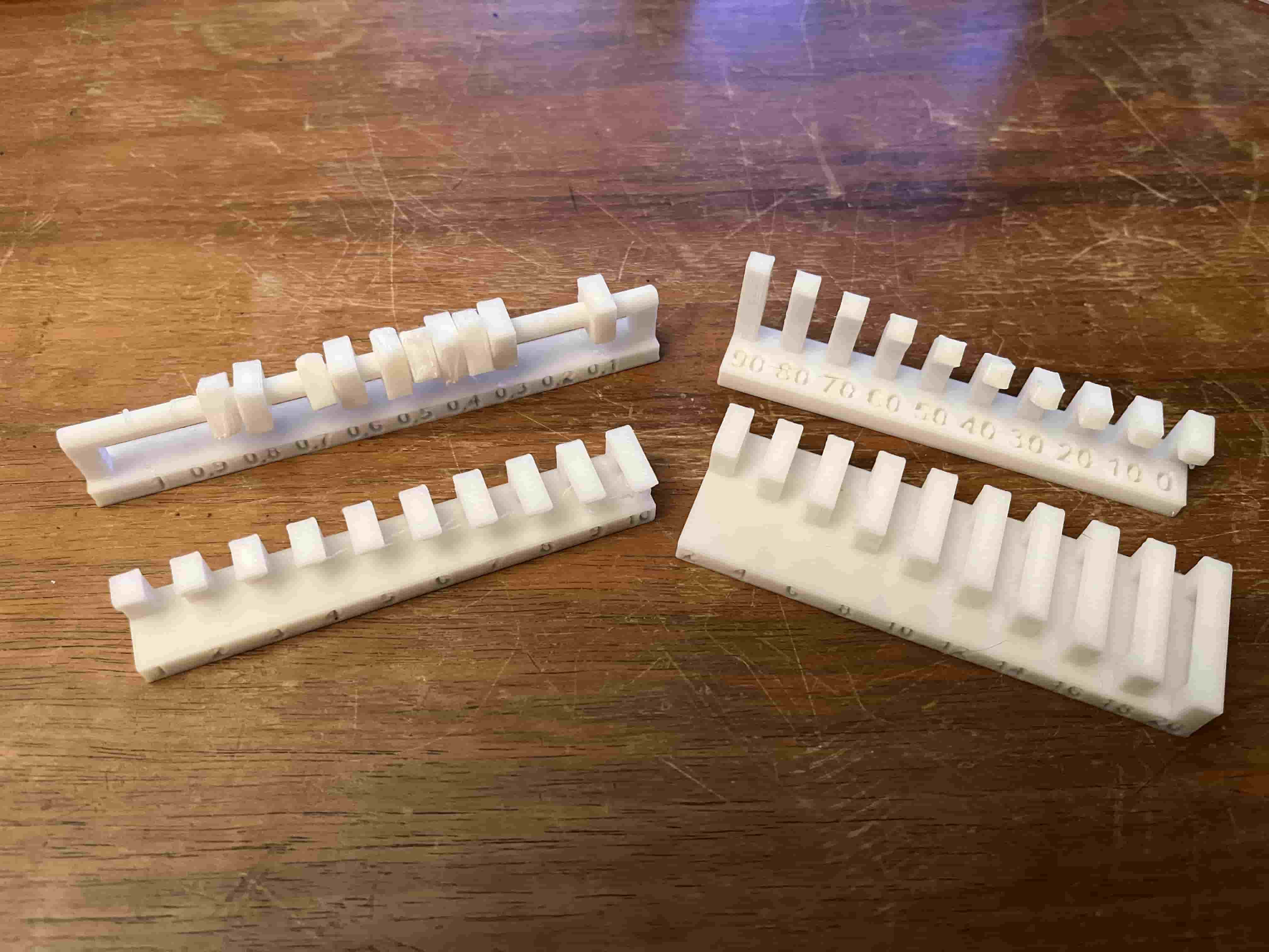
For my part of the group assignment, I did some basic tests on the Sindoh 3DWOX1 to check out its print limitations. To do that, I also had to do a quick setup for the bed leveling and z-offset.


When I compared my results to the performance of the other printers in our lab, I realized how different one 3D design can be when printed on different machines. For one, it depends on the machine capabilities and the material used. And interestingly enough, it also depends on the different slicers used and the whole printing optimization algorithms that run in the background of each slicer in terms of motor control and all that. In addition to that, I discovered that a well-tuned gcode run on a budget printer can outperform a higher-end printer, so that one can have quality prints even if access to good printers is limited.
3D Scanning
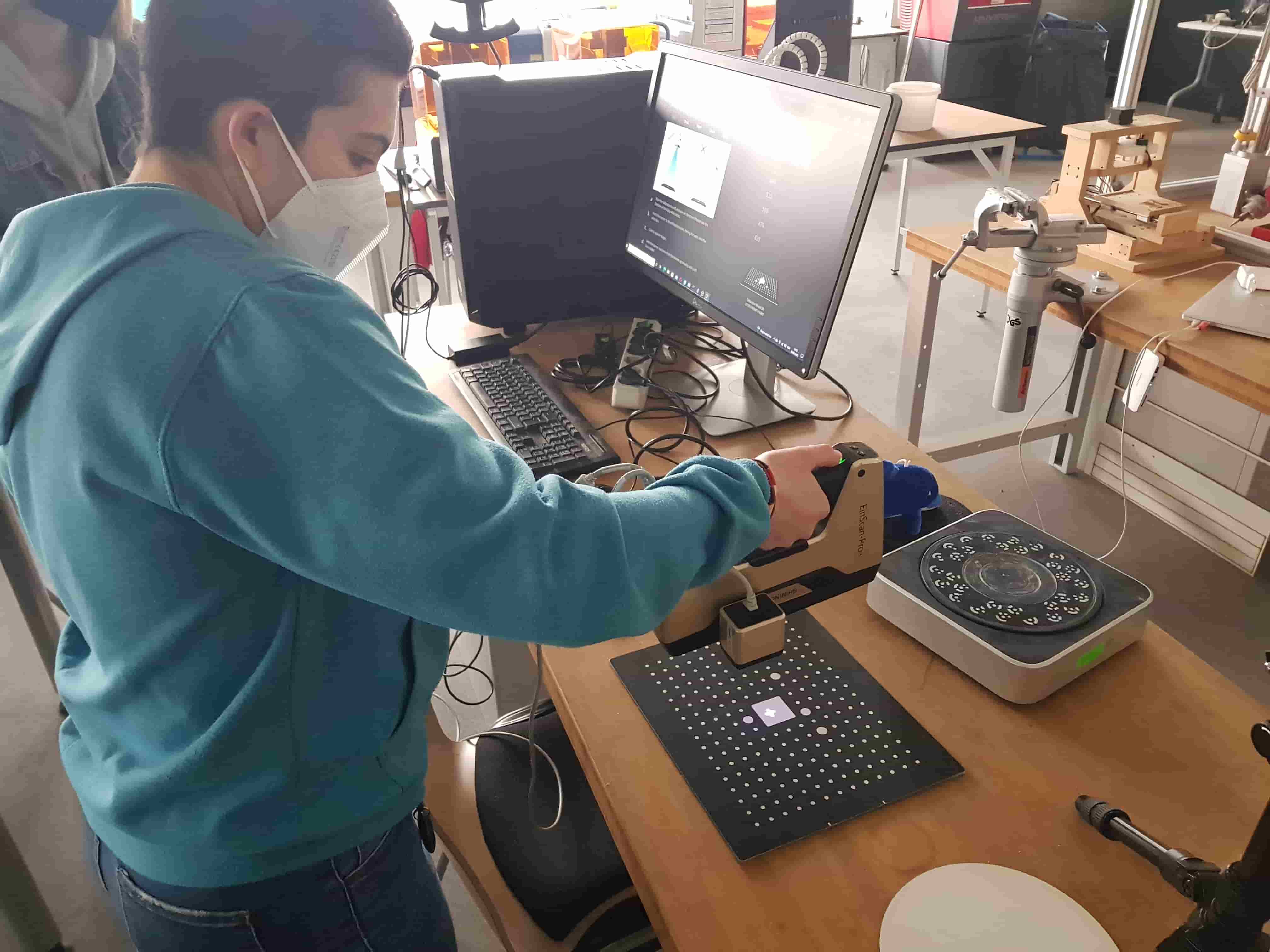
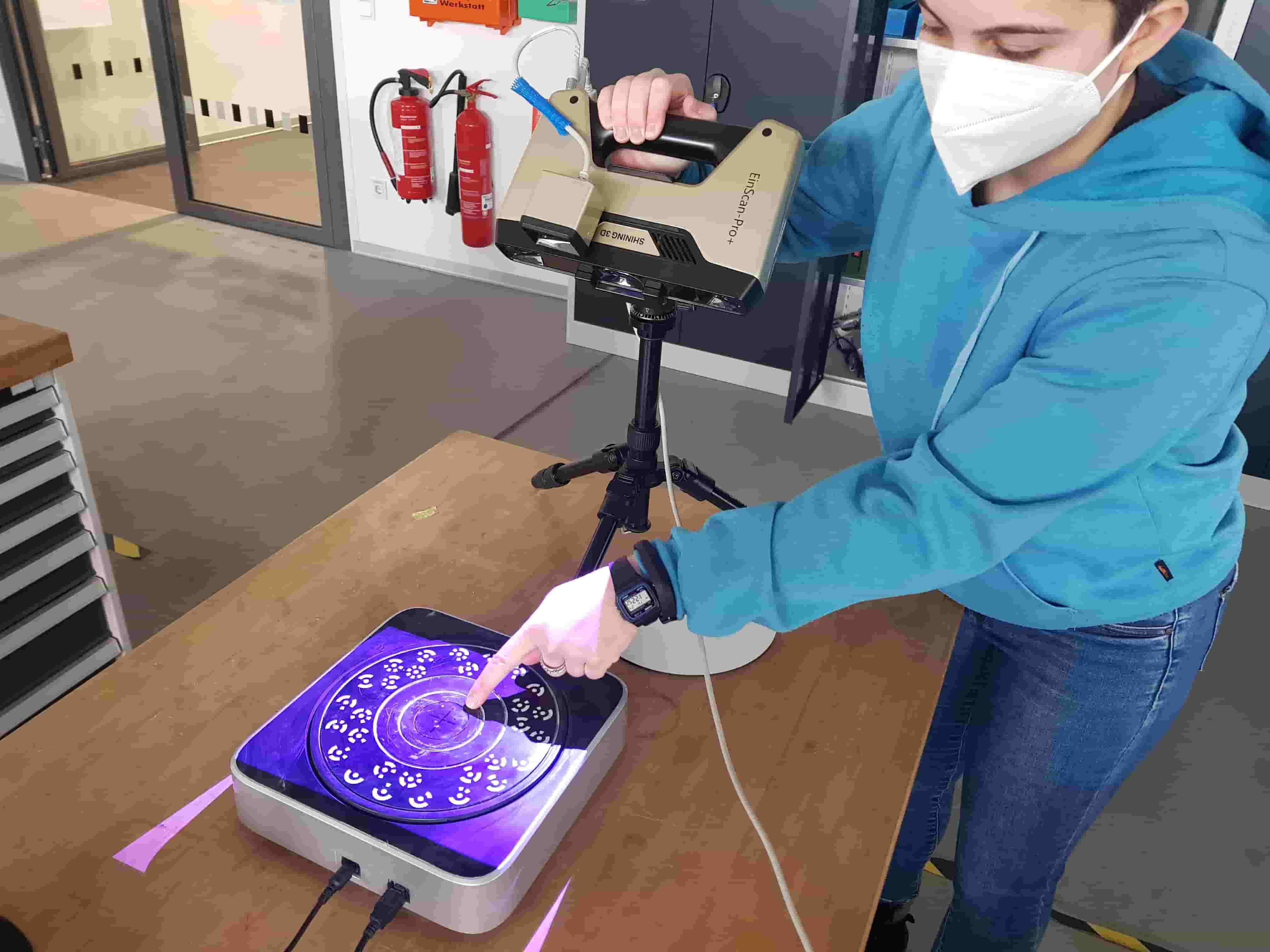
For this task, we used our EinScan Pro+ 3D scanner with the color camera and turntable attachments.
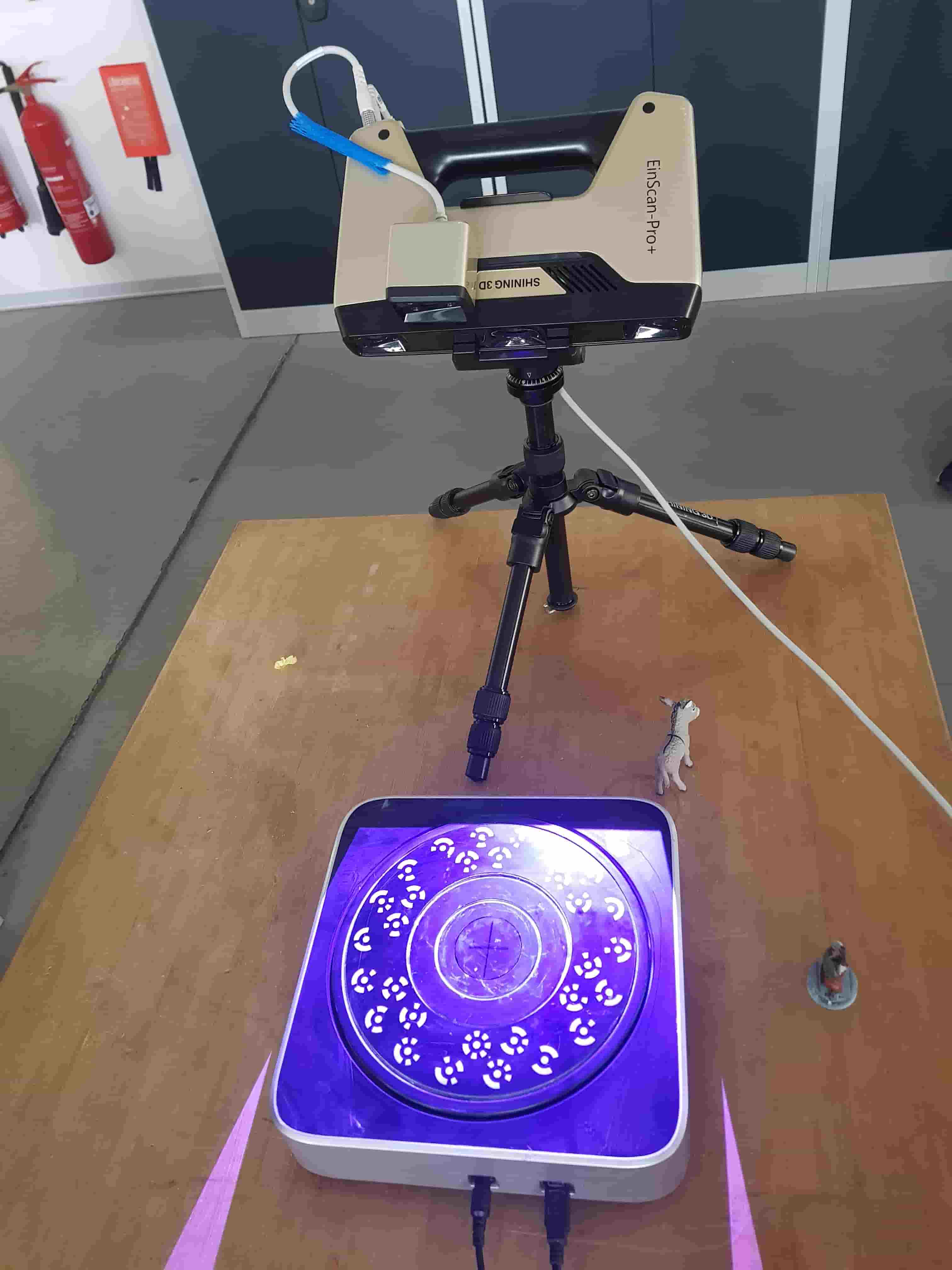
Before starting the scan, we had to calibrate the scanner using the calibration grid and the built-in instructions in the software.
After the calibration was done, I had to set up my scan so that the cross sign projection is in the middle of the turntable, and made sure that the scanning field marked by the purple light is as square as possible.
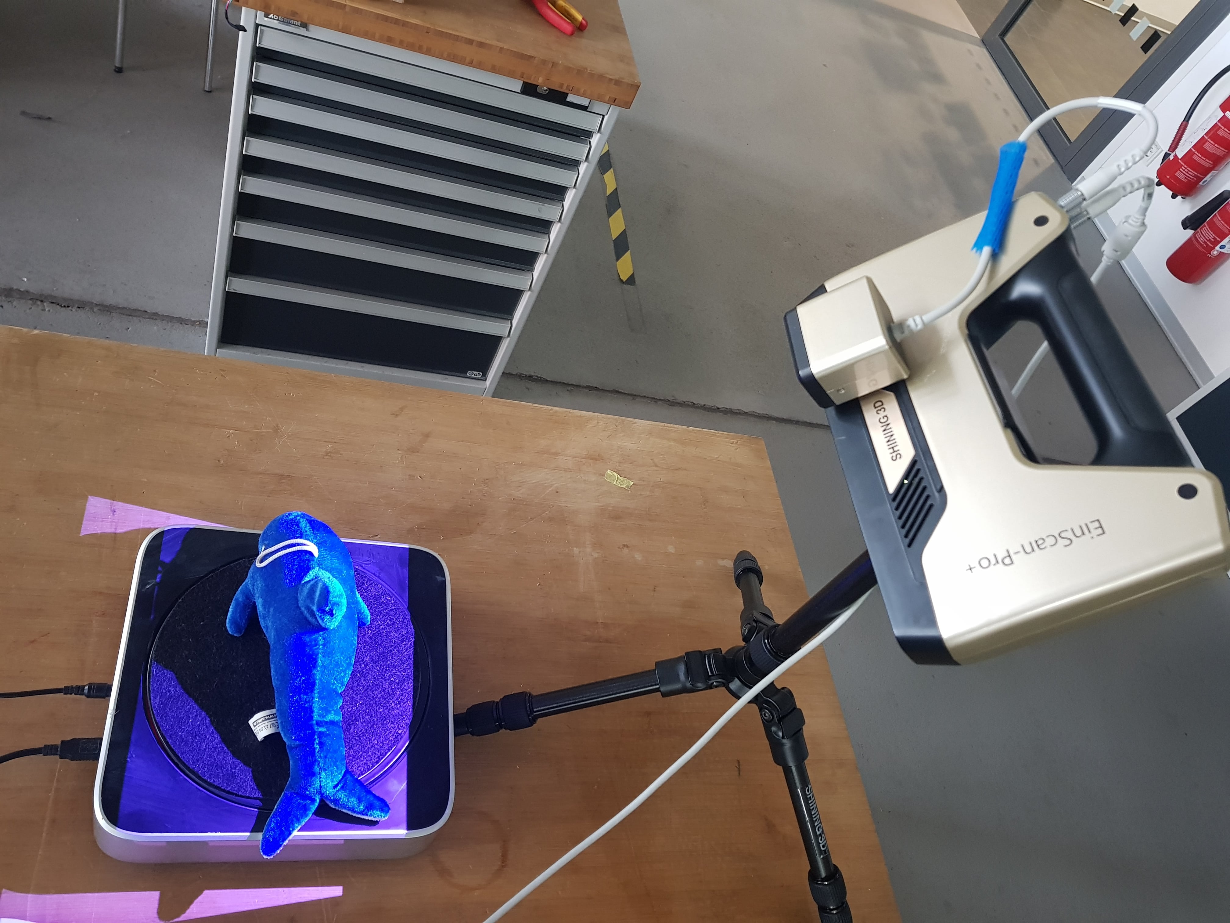
Scanning the dolphin
When I was ready to scan, I placed my stuffed dolphin on the turntable and made sure the scanner's width range spanned the whole body.
DISCLAIMER: scanning this dolphin did not work :/.
Then, it was time to turn to the EinScan Pro software and start the scan. Here, I chose the Fixed Scan with the Texture Scan options, and toggled the Features mode because some of the coded targets on the turntable were covered by the dolphin.
-min.jpg)
-min.jpg)
-min.jpg)
-min.jpg)
After the first scan of 5 individual shots was done, I clicked on Apply Edit and continued to the next batch of scanning. There, I changed the number of steps to an even number (10) so that the angle division means that the scanner will capture different orientations when rotating when compared to the division by an odd number (5 in my case). However, I received the warning message that the image verification has failed. When this happens, it usually means that the lighting conditions have changed. So I played with the brightness slider until I found an acceptable setting for the program to proceed with the scanning, and changed the number of steps to 12 for more scan details.
-min.jpg)
-min.jpg)
-min.jpg)
-min.jpg)
Next scanning batch:
-min.jpg)
-min.jpg)
-min.jpg)
For this batch, I had to do some editing to remove the platform that was scanned under my dolphin. To do that, I highlighted the unwanted parts and deleted them, and then clicked on Apply Edit.
-min.jpg)
-min.jpg)
-min.jpg)
-min.jpg)
What resulted from these two scan batches, though, was not a stitched up dolphin model as I had hoped, but rather a combination of the scans without the software being able to identify the common features and stitch the files in the correct orientation.
-min.jpg)
-min.jpg)
I then thought of positioning the dolphin in a different orientation hoping that it will help the software find the matching features and be able to stitch the model eventually. To do that, I decided to abuse the scanner's blind spot: I propped the dolphin on a glass since the scanner does not see transparent objects, and attempted a couple of scans which turned out nicely.

-min.jpg)
Sadly though, when I tried stitching the scans together it all ended up with a bigger mess than it originally was :(.
-min.jpg)
-min.jpg)
-min.jpg)
-min.jpg)
So I just aborted my mission at that point and decided to scan some other object, since the dolphin seems to be a tough one on the scanner. I think this might be because it has a weird texture and is not a solid object and therefore its features change with the orientation it is put in.
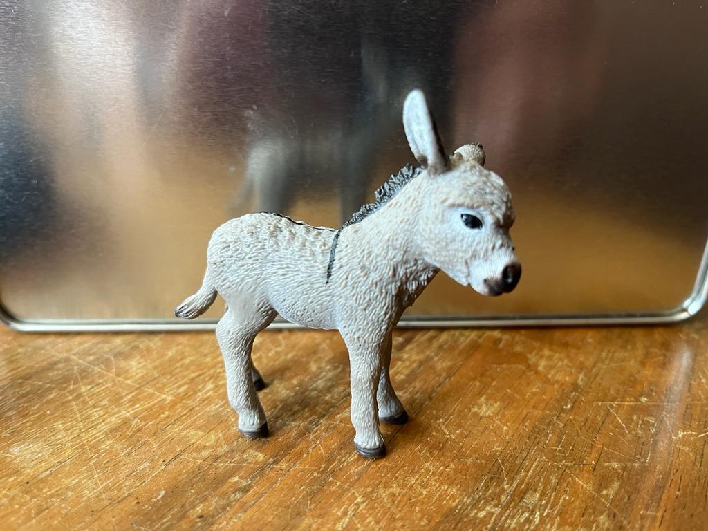
Scanning the donkey foal
I then chose to scan my Schleich donkey foal since it is a solid matt object that should be easily captured by the 3D scanner.
I started by setting the brightness slider to an acceptable setting and went ahead with a test batch.
.jpg)
.jpg)
.jpg)
It worked fine, so I went ahead and started the first batch.
.jpg)
.jpg)
Another batch with the donkey on its side.
.jpg)
.jpg)
And one last batch with it upside-down.
.jpg)
.jpg)
.jpg)
With the scans stitching together nicely, I was finally ready to mesh my model.
.jpg)
I chose Watertight Model, and decided to go for High Detail.
.jpg)
.jpg)
And here it is!
3D Printing
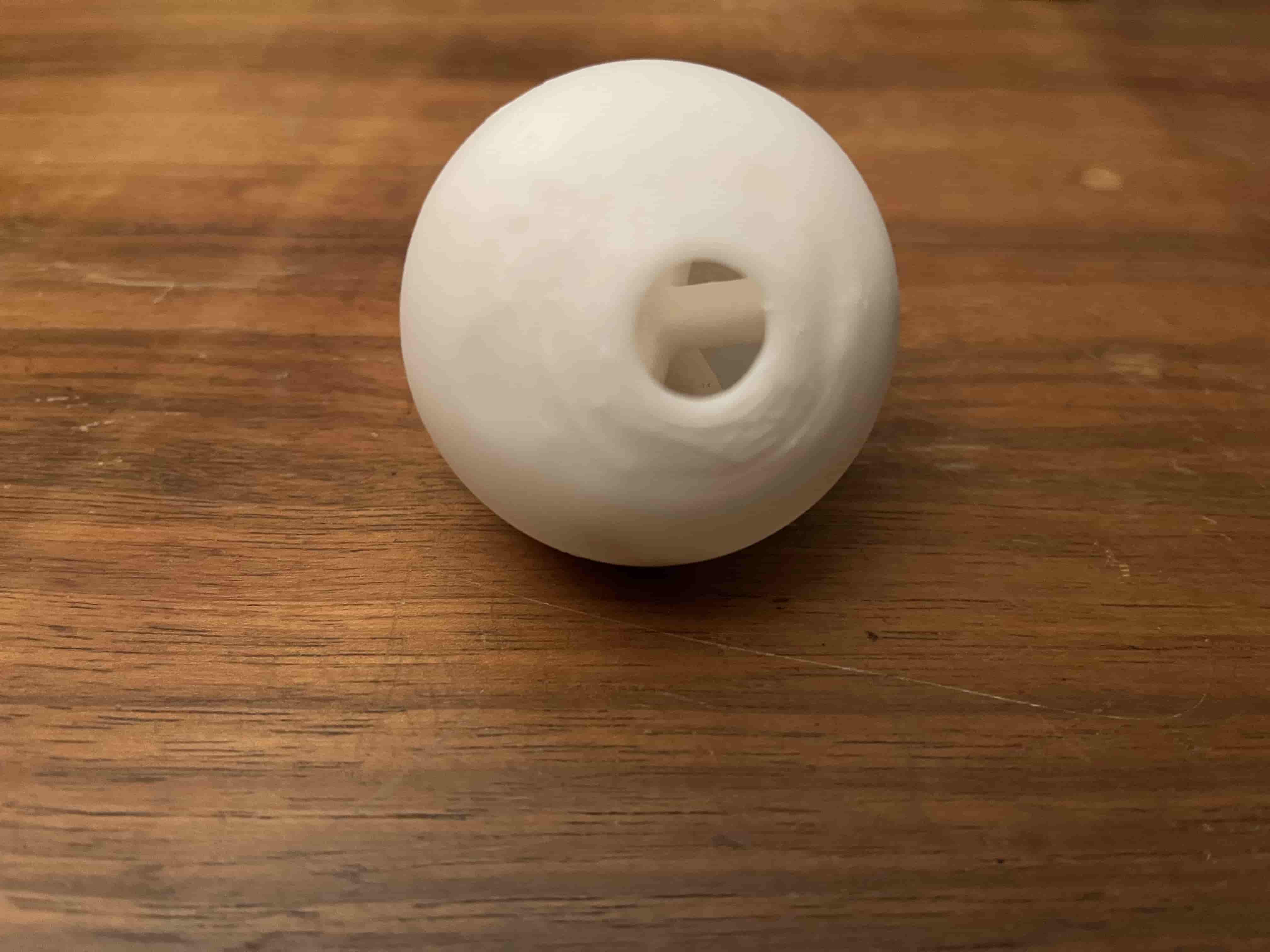
For this week's individual 3D printing submission, I decided to design a treat dispensing ball for my cat and print it on the Sindoh.

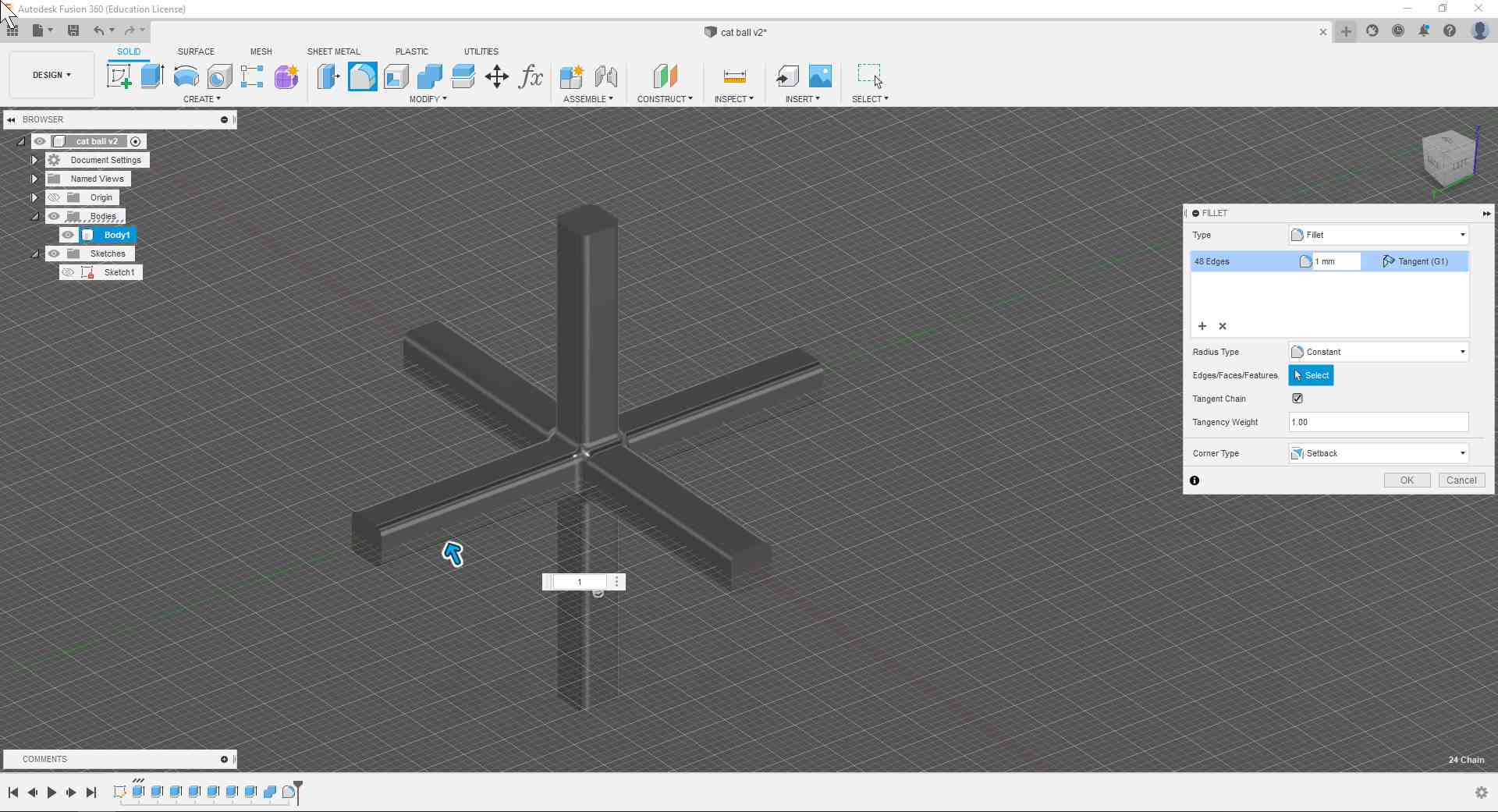
Designing the Ball
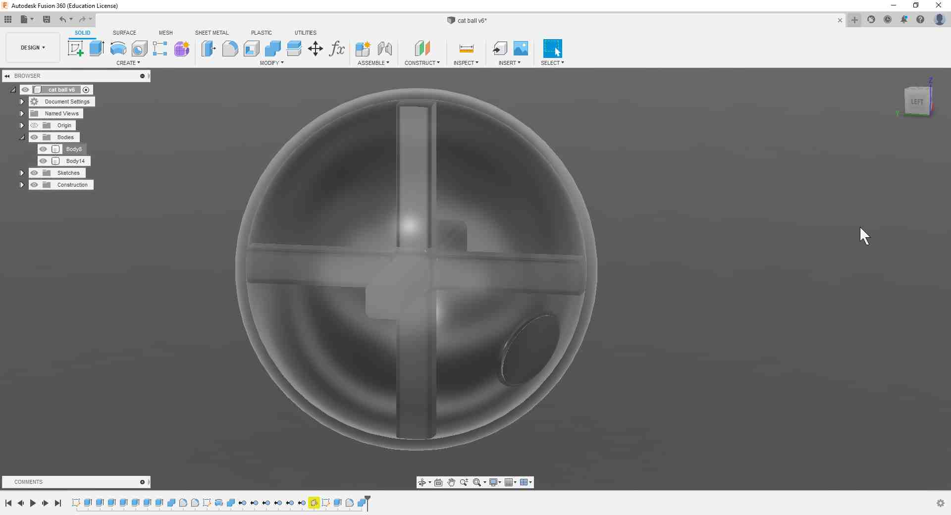
To start with, I drew a box and extruded all its faces by a distance more than the ball size I want. For the extrusion, I kept all extruded elements as independent bodies so that I can continue extruding the remaining cube faces without including the extruded rods. When I was done, I joined all of the bodies using the Combine function, and then applied a fillet to all the edges:
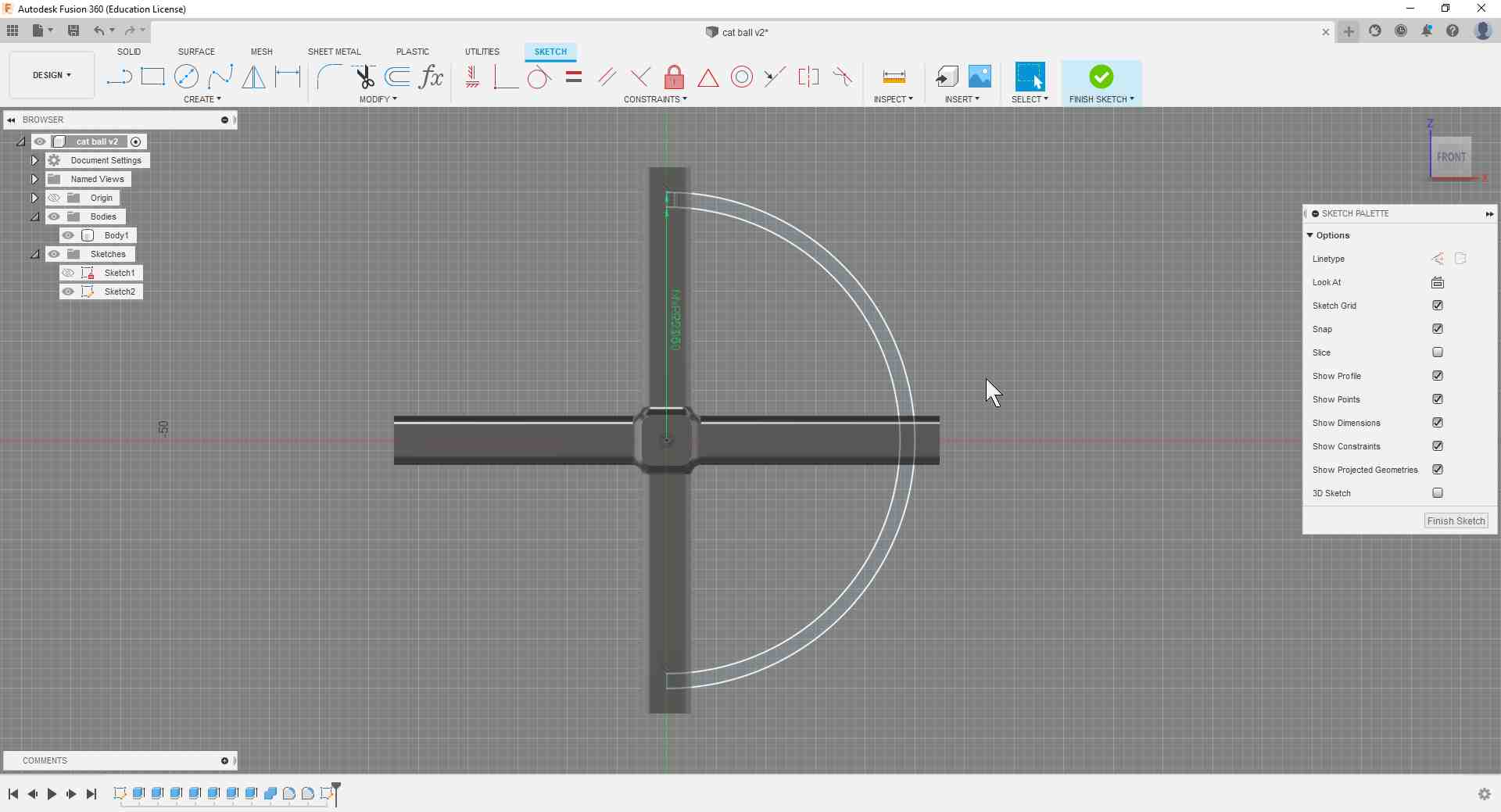
After that, I sketched two half-circles and connected their ends with straight lines to create a slice of the sphere that is going to become the ball:
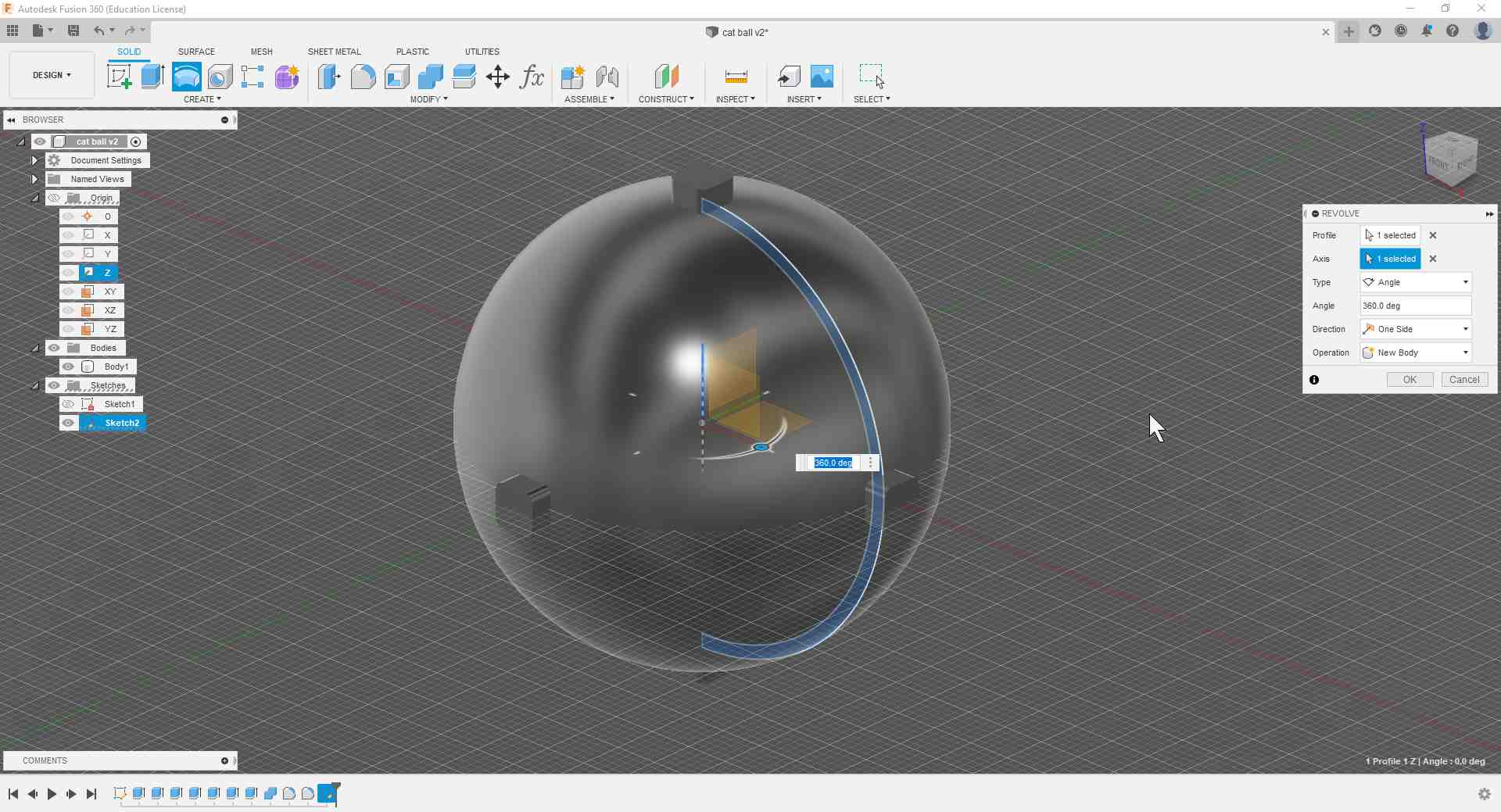
Then I revolved the sketch around the z-axis, ending up with my ball.
To get rid of the extra length of the extruded rods, I used the Combine function again but with the Cut operation and used the sphere as a cutting tool.

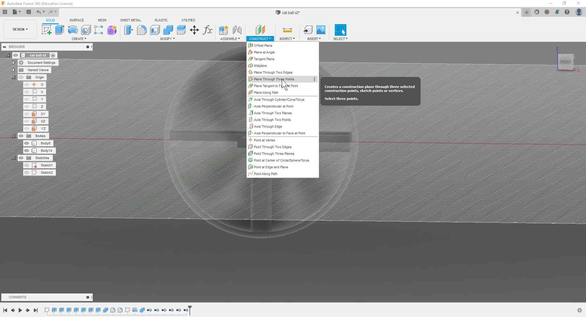
Then after removing the remaining bits of the rods, I constructed a plane that connects the vertices of three rods. To do that, I had to momentarily suppress the Fillet feature to be able to select the endpoints.
.jpg)
After that, I used the new plane to create a sketch of a circle, and then used the Extrude function to cut out a hole in the sphere. Additionally, I applied a fillet to the edges of the cut circle.
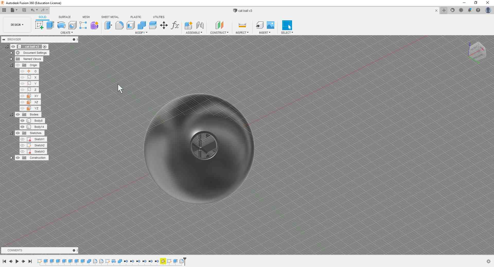
I then played with the opacity settings of the ball and made it 50% transparent so I can see the rod geometry inside.
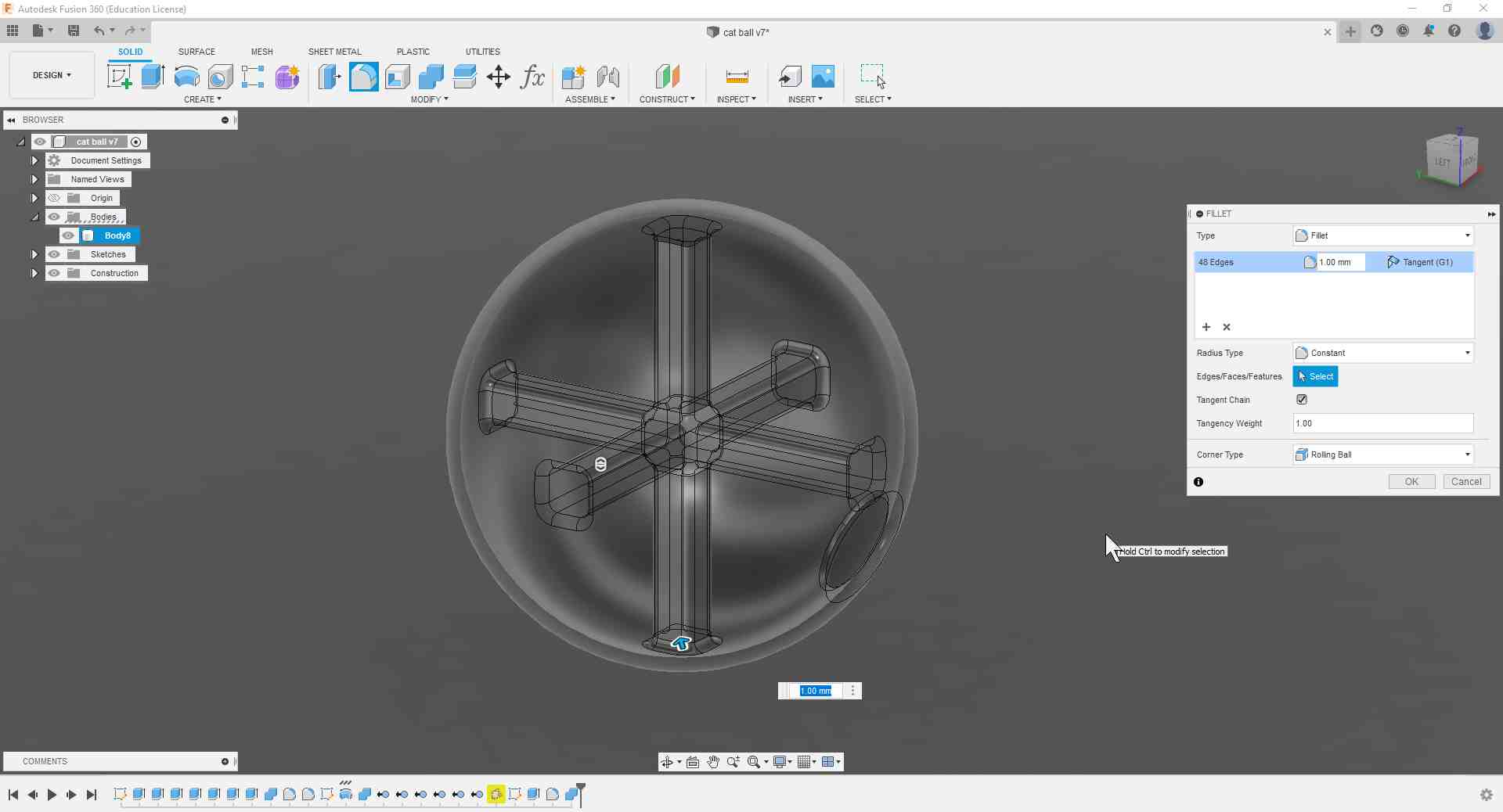
That made me aware of the hard edges connecting the sphere to the rods, so I decided to add fillets to all these junctions. Before I did that, though, I had to combine the two bodies into one so that the fillet function works properly.
Slicing the Ball
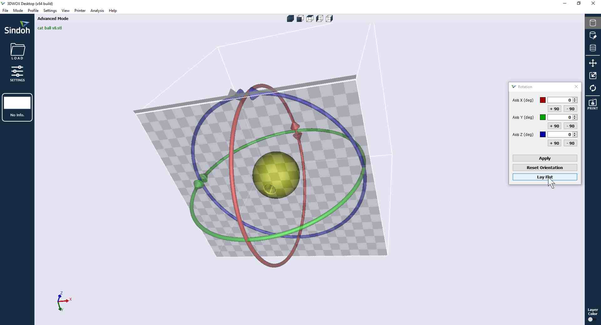
After I was satisfied with my result, I exported the file as an STL and imported it into the Sindoh 3DWOX Desktop slicer. Then I had to rotate the ball using the Lay Flat function until the hole face was placed flush on the virtual heatbed.
I then sliced the ball with the default settings just to get a feel of how the print would look like on the inside.

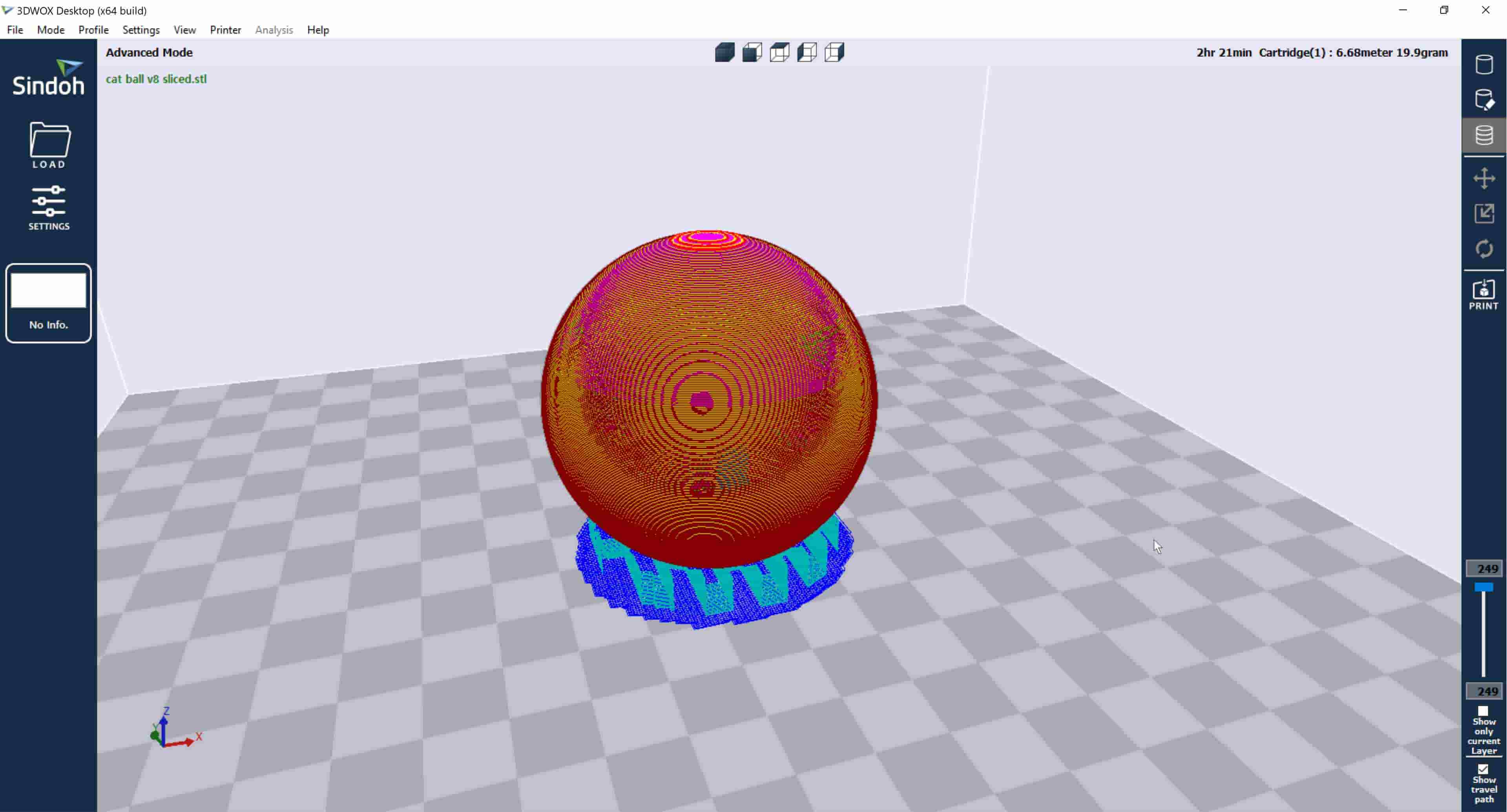
Then I added a Raft to make sure that my ball stick to the buildplate, and set the Infill to 15%.
-min.jpg)
Here is the sliced model after clicking Layer Viewer, with an estimated print time of 2 hours and 21 minutes:
I then headed to the printer knowing that I have done the appropriate bed leveling and z-axis calibration, and started my print.
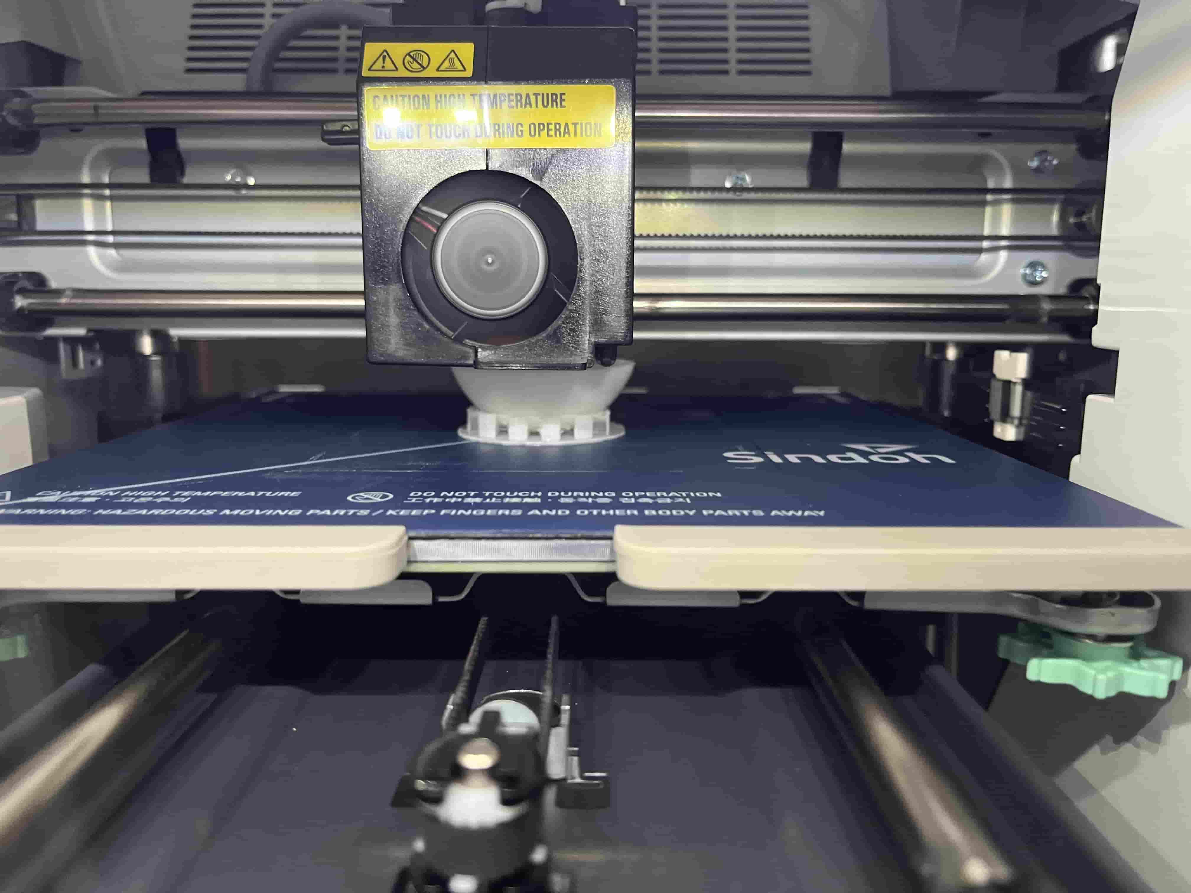
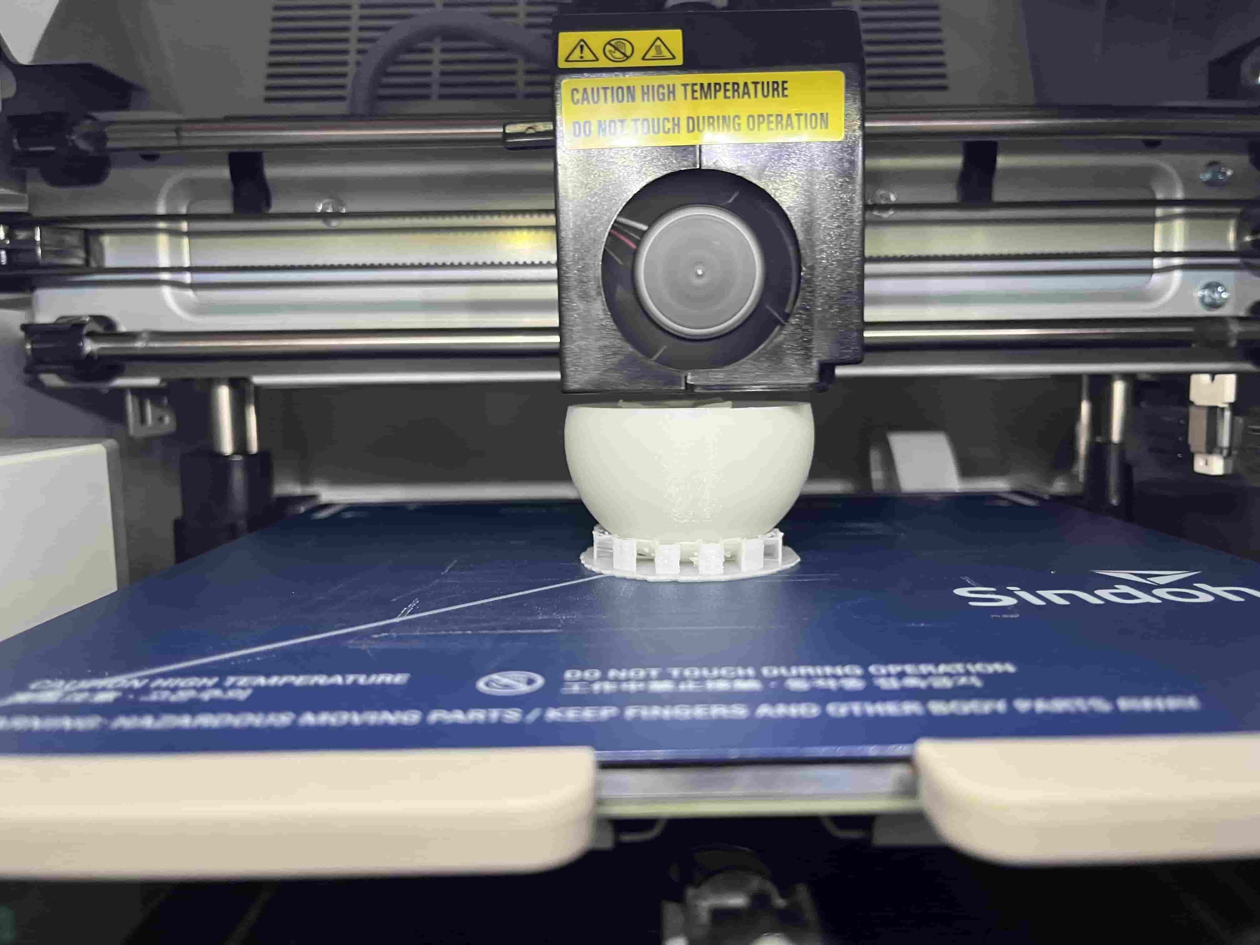
This is how it looks on the inside during a print pause:
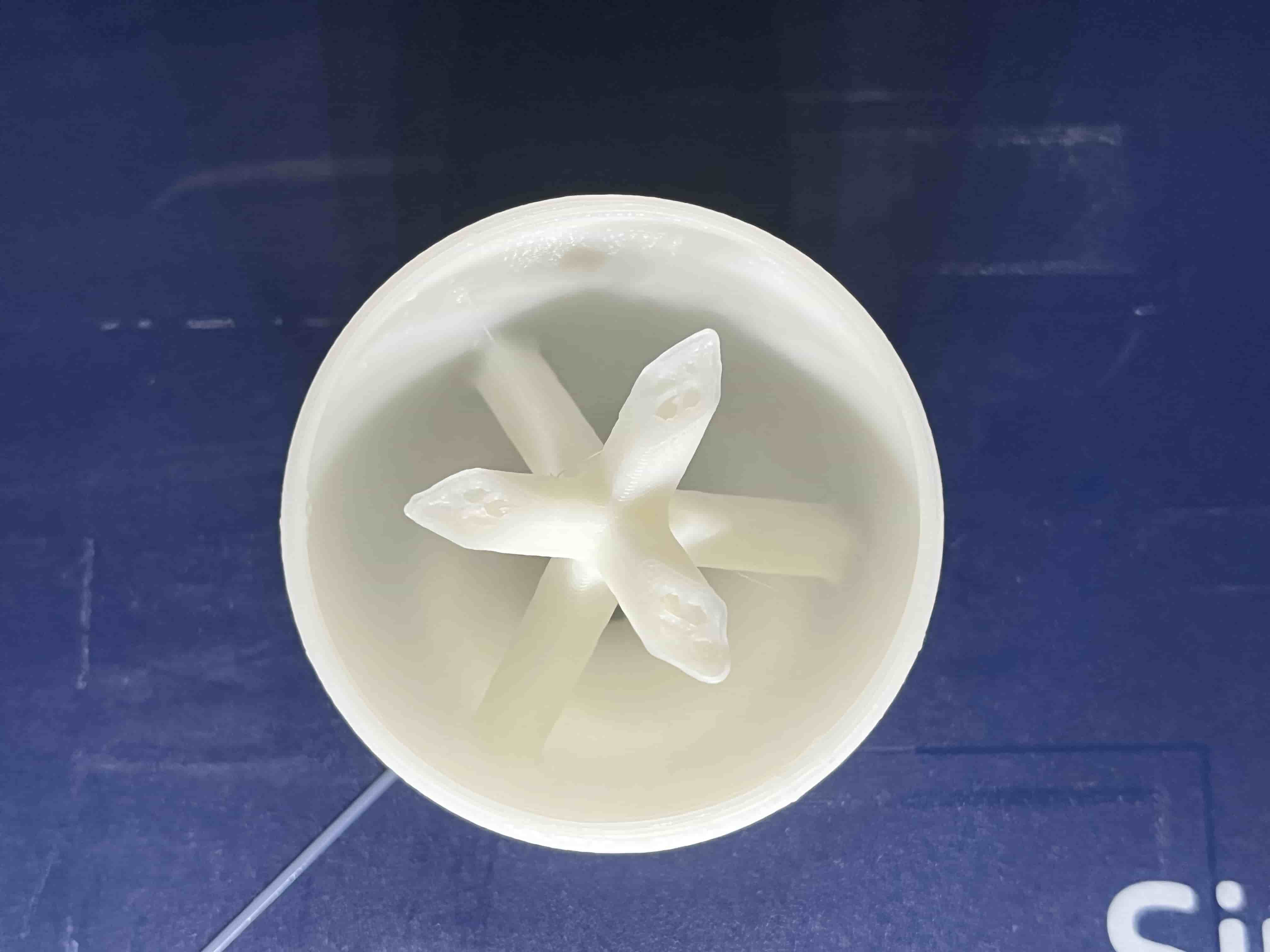
And it is printed!
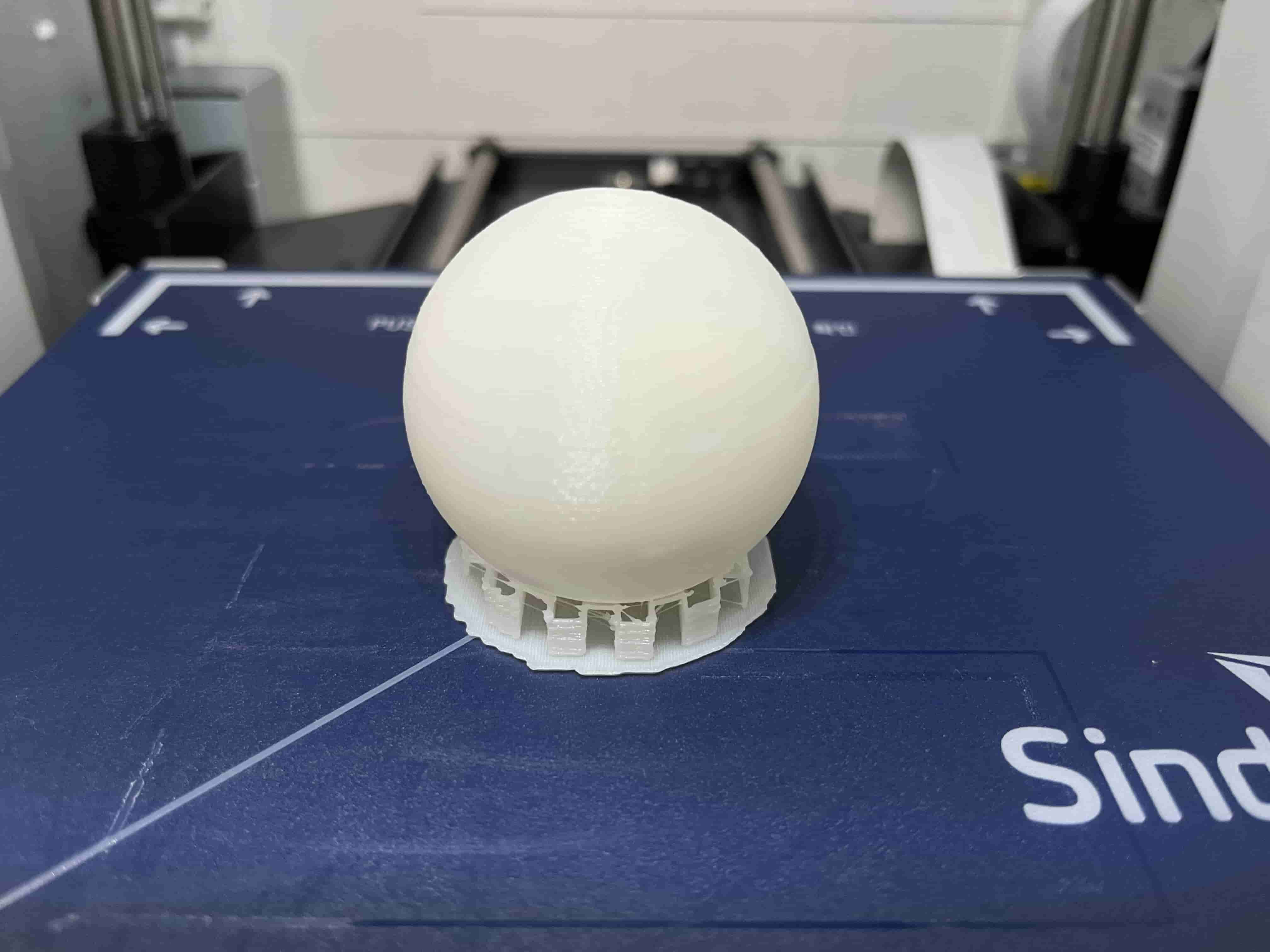
Before this ball goes into commission, the support material has to be removed.
May I present, the treat dispensing ball :D