Leen Nijim
Assignment 9
Embedded Programming
Task
Our task this week was to program our boards to do something using multiple programming languages. I used the Arduino coding language and then tried my luck with translating these programs to C code.
What You Need
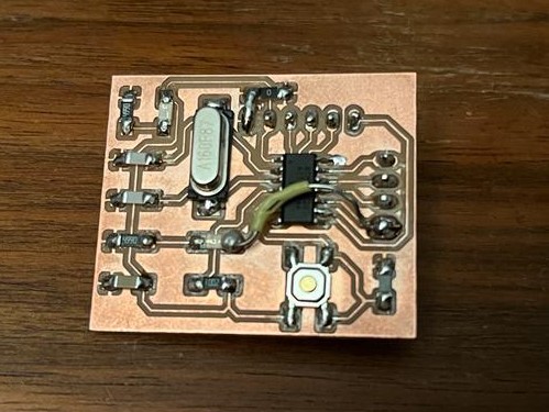
- Hello board ATtiny44 I made during Assignment 7.
- ISP programmer (Arduino Uno in this case).
Files to Download
Hero Shots
Group Assignment
For our group assignment, please click here.
ATtiny44 Datasheet
Reading through the datasheet of the ATtiny44 was not the first time I've skimmed through such documentation, so I roughly knew what to expect to find there. The most useful place after the ctrl + F keyboard combination is the table of contents. My tactic for finding information in such documents is to skim through that table, and once I've located the general region I expect to find the information in, I navigate there and use the Find function to look for the specific name or phrase I need. This I found to be much faster than using the Find function straight away, since more often that not the keyword that I'm looking for is repeated multiple times throughout the hundreds of pages of such documents.
I also like to go through the brief descriptions of the board pinout and check out what basic functions I can make use of. And in case my application makes use of high computational speeds where performance should be optimized, I go through the registers documentation and check out how to manipulate them on the low level, as well as how to make best use of the available flags and system interrupts. Another good section to look at is the clocking options. This is, for example, where I went back to when I was designing my own ATtiny44 board and wanted to use an external clock to drive my microcontroller.
An additional important part for the assignment this week is how to access and edit input/output pins. For that I found it useful to just document the description from Section 10.1.1 Configuring the Pin and Section 10.1.2 Toggling the Pin here:
Each port pin consists of three register bits: DDxn, PORTxn, and PINxn. As shown in “Register Description” on page 72, the DDxn bits are accessed at the DDRx I/O address, the PORTxn bits at the PORTx I/O address, and the PINxn bits at the PINx I/O address.
The DDxn bit in the DDRx Register selects the direction of this pin. If DDxn is written logic one, Pxn is configured as an output pin. If DDxn is written logic zero, Pxn is configured as an input pin.
If PORTxn is written logic one when the pin is configured as an input pin, the pull-up resistor is activated. To switch the pull-up resistor off, PORTxn has to be written logic zero or the pin has to be configured as an output pin. The port pins are tri-stated when reset condition becomes active, even if no clocks are running.
If PORTxn is written logic one when the pin is configured as an output pin, the port pin is driven high (one). If PORTxn is written logic zero when the pin is configured as an output pin, the port pin is driven low (zero).
Writing a logic one to PINxn toggles the value of PORTxn, independent on the value of DDRxn.
An example of how to set up port A pins 0 and 1 high, 2 and 3 low, and define the port pins from 4 to 5 as input with a pull-up assigned to port pin 4 is found under Section 10.1.7 Program Examples.
unsigned char i;
...
/* Define pull-ups and set outputs high */
/* Define directions for port pins */
PORTA = (1<<PA4)|(1<<PA1)|(1<<PA0);
DDRA = (1<<DDA3)|(1<<DDA2)|(1<<DDA1)|(1<<DDA0);
/* Insert nop for synchronization*/
_NOP();
/* Read port pins */
i = PINA;
...
Programming the ATtiny44
Setting up the Arduino IDE
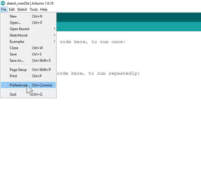
Before I am able to test my board, I have to set up the Arduino IDE to recognize and support the ATtiny44 microcontroller. To do that, I went to File > Preferences.
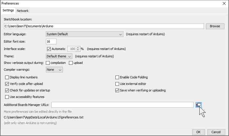
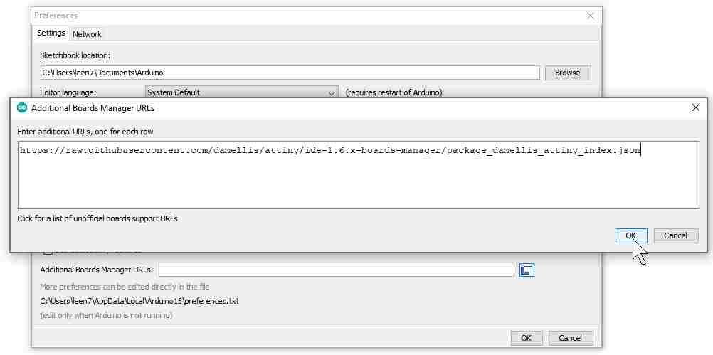
And then clicked on the button next to Additional Boards Manager URLs to add the link https://raw.githubusercontent.com/damellis/attiny/ide-1.6.x-boards-manager/package_damellis_attiny_index.json.
Then I went to Tools > Board > Boards Manager.. to install the ATtiny boards.
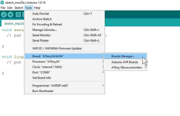
I typed "attiny" in the search bar and clicked Install.

I then went on to check whether the installation was successful and looked for the boards under the Tools > Board menu.
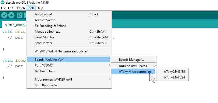
Burning the Bootloader
When that was ready, I went ahead and connected my board to an Arduino Uno board.

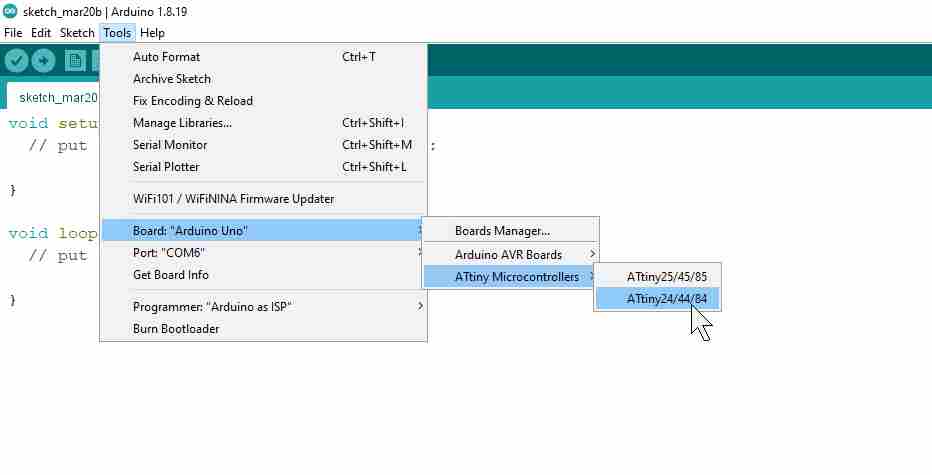
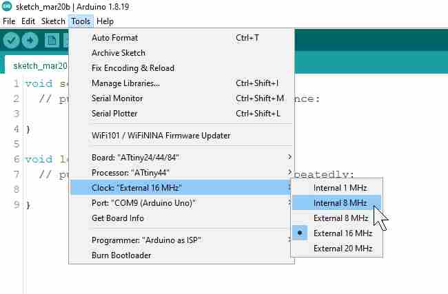
After that, I started changing the settings under the Tools menu to be able to program the hello world board using the Uno board.


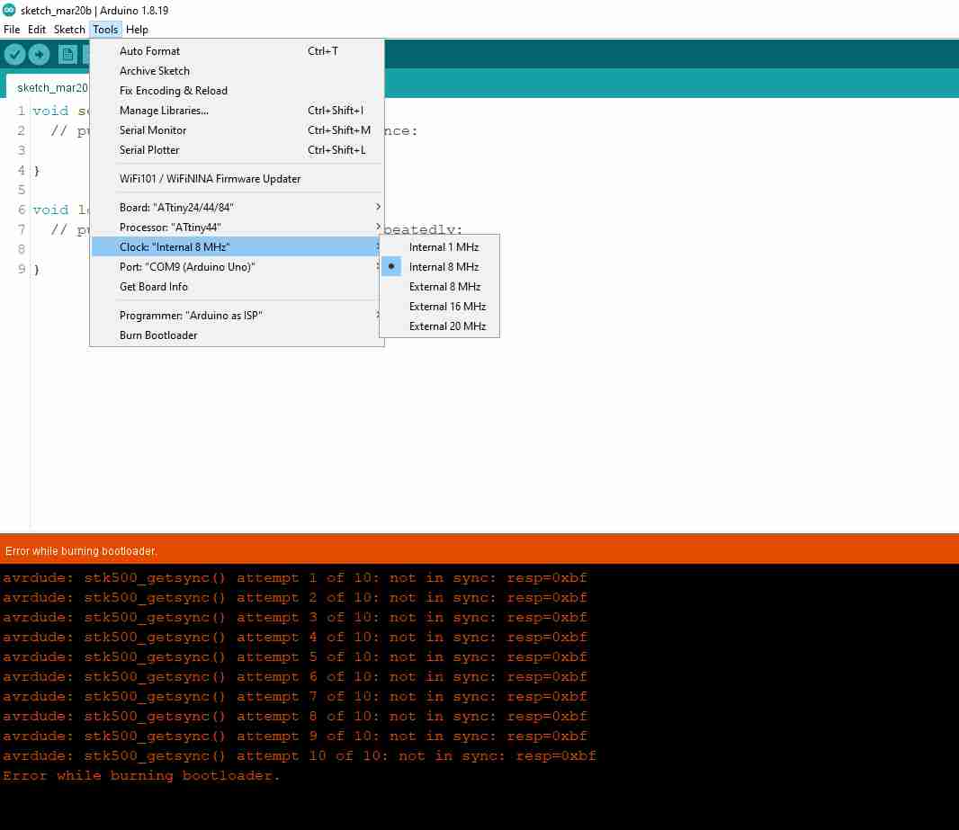
But then I ran into the error about something not being in sync, so I thought to try and use the ATTiny44 internal clock at 8 MHz for burning the bootloader instead.
But that also ended with the same result.
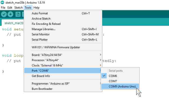
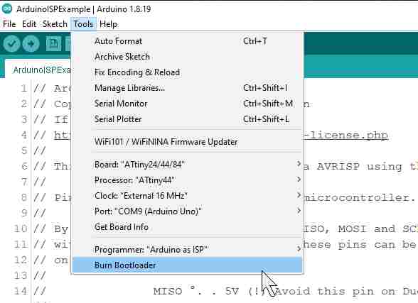
After I looked up the steps of programming the ATtiny44 online again, I realized that I have skipped a step in the beginning and that it might be the reason I am getting the sync errors. So I went back to turn the Arduino Uno board I am using to an ISP programmer. To do that, I navigated to File > Examples > Built-in Examples > ArduinoISP and connected the Uno board and uploaded the code.


And then gave it another go while keeping the external clock settings.
This time I got another error, which was good news and bad news at the same time. Good news was that I managed to fix the sync error, but bad news because of the new error. However, this time the error message was more helpful and told me to check my physical board connections before trying again.
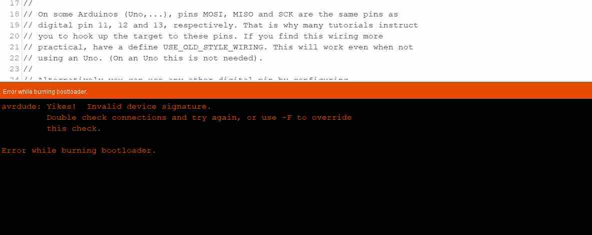
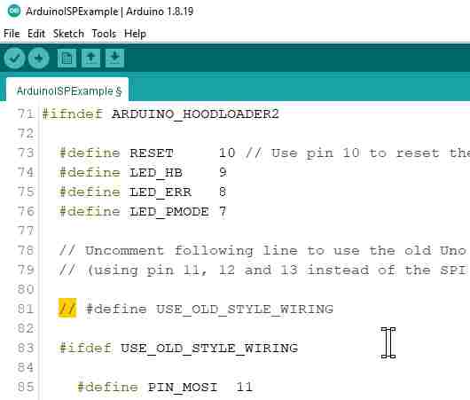
After I inspected my wires and made sure everything was connected to where it should be, which it was, I realized that the 5V wire had a loose connection and the power LED on my board was flickering sometimes when I moved the connected boards. So I decided to change that wire and also try connecting the ISP wires to the other built-in pins on the arduino as mentioned in the ArduinoISP example, and made sure to uncomment the corresponding code line.
| Arduino Uno | ATtiny44 |
|---|---|
| Pin 5V | Pin 1 (VCC) |
| Pin 10 | Pin 4 (RESET) |
| Pin 11 | Pin 7 (MOSI) |
| Pin 12 | Pin 8 (MISO) |
| Pin 13 | Pin 9 (SCL) |
| Pin GND | Pin 14 (GND) |
-min.jpeg)
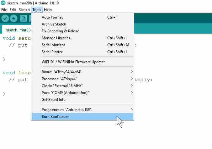
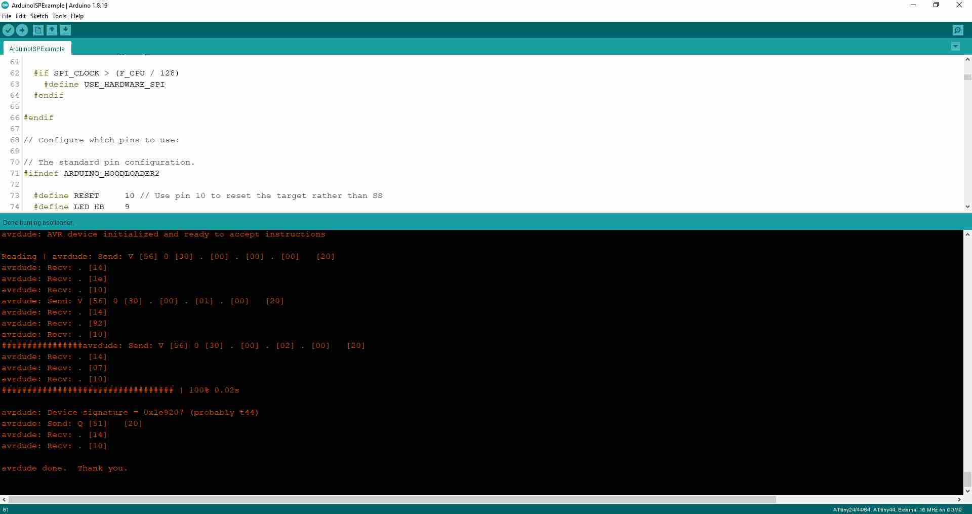
And gave it yet another try...

That was it! The bootloader was successfully burnt onto the ATtiny44.
Test Code
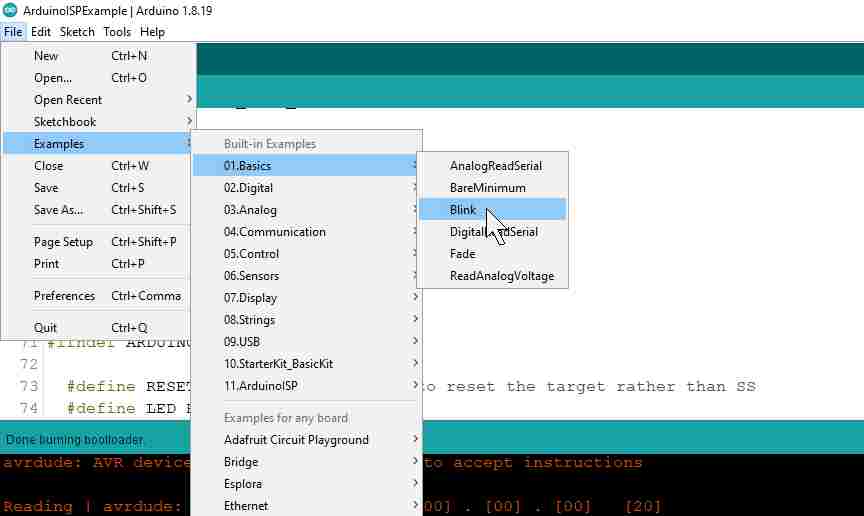
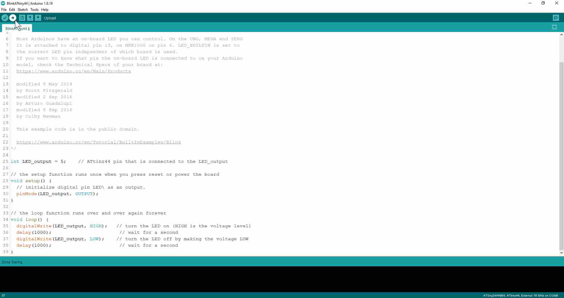
For a simple test code, I navigated to File > Examples > Basics > Blink to try make the LED on my hello world board blink.
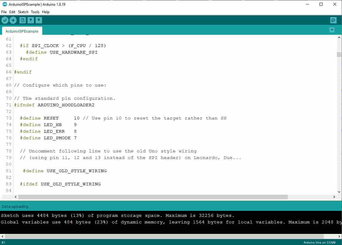
I made sure to change the LED pin definition to pin 5 according to my board design, and then hit Upload.
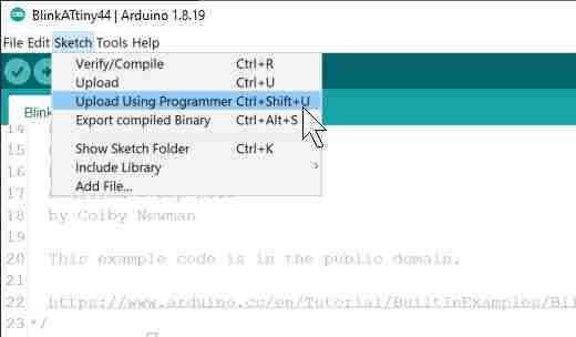
To my disappointment, absolutely nothing happened on my board although I received no errors from the Arduino IDE and the upload was successfully done. So after looking into this with my local instructor, I realized I have two issues I needed to fix. The first was that I should go to Sketch > Upload Using Programmer instead of the usual method because otherwise I would be sending the code to the Arduino Uno instead of the ATtiny44.
The second issue is that to address the ATtiny44 pin that has the LED connected to it, I should use the pin name from the datasheet and not the pin number on the chip, which in this case means PB2 instead of 5. However, going back to the datasheet at that point made me realize that the pin I have connected the on-board LED to is not capable of controlling the LED, as it is not an input/output pin.
To solve that issue, I had to go back and do some unconventional board debugging where I severed the trace connecting the LED to pin 5 on the ATtiny44 and connected it to pin 10 using a short jumper wire.
Blink LED Program
Now that I was ready to start programming the ATtiny44, I decided to start with the example code to make the LED blink continuously first using the Arduino code and then C code.

Arduino Code (698 Bytes)
/*
Blink

Turns an LED on for one second, then off for one second, repeatedly.

Modified from the code found in:

https://www.arduino.cc/en/Tutorial/BuiltInExamples/Blink
*/

 #define LED PA3    // ATtiny44 pin 10 that is connected to the on-board LED

// the setup function runs once when you press reset or power the board
 void setup() {
	// initialize digital pin LED as an output.

	pinMode(LED, OUTPUT);
  }

 // the loop function runs over and over again forever
 void loop() {
	digitalWrite(LED, HIGH);   // turn the LED on (HIGH is the voltage level)
	delay(1000);                       // wait for a second
	digitalWrite(LED, LOW);    // turn the LED off by making the voltage LOW
	delay(1000);                       // wait for a second

	}
C Code (82 Bytes)
/*
Blink

Turns an LED on for one second, then off for one second, repeatedly.
*/

#include
#include

int main(void)
{
  DDRA |= (1<<DDA3);      // set LED pin as output
  PORTA |= (1<<PA3);     // turn on LED by setting pin to high
  while (true)            // repeat continuously
  {
	PINA |= (1<<DDA3);   // toggle state of LED pin
	_delay_ms(1000);
  }
  return (0);
}
So, for the same function the program needed to occupy almost three quarters of a kilobyte using Arduino code and libraries, while only 82 bytes were needed using C language.
Toggle LED with Push Button Program
Arduino Code (858 Bytes)
/*
  Debounce

  Each time the input pin goes from LOW to HIGH (e.g. because of a push-button
  press), the output pin is toggled from LOW to HIGH or HIGH to LOW. There's a
  minimum delay between toggles to debounce the circuit (i.e. to ignore noise).

  Modified from the code found in:

  https://www.arduino.cc/en/Tutorial/BuiltInExamples/Debounce
*/

#define led PA3         // pin 10 on ATtiny44 where LED is mounted
#define pButton PA7     // pin 6 on ATtiny44 where push button is mounted


bool ledState = HIGH;         // the current state of the output pin
bool buttonState;             // the current reading from the input pin
bool lastButtonState = LOW;   // the previous reading from the input pin

// the following variables are unsigned longs because the time, measured in
// milliseconds, will quickly become a bigger number than can be stored in an int.
unsigned long lastDebounceTime = 0;  // the last time the output pin was toggled
unsigned long debounceDelay = 50;    // the debounce time; increase if the output flickers

void setup() {
  pinMode(pButton, INPUT);
  pinMode(led, OUTPUT);

  // set initial LED state
  digitalWrite(led, ledState);
}

void loop() {
  // read the state of the switch into a local variable:
  bool reading = digitalRead(pButton);

  // check to see if you just pressed the button
  // (i.e. the input went from LOW to HIGH), and you've waited long enough
  // since the last press to ignore any noise:

  // If the switch changed, due to noise or pressing:
  if (reading != lastButtonState) {
    // reset the debouncing timer
    lastDebounceTime = millis();
  }

  if ((millis() - lastDebounceTime) > debounceDelay) {
    // whatever the reading is at, it's been there for longer than the debounce
    // delay, so take it as the actual current state:

    // if the button state has changed:
    if (reading != buttonState) {
      buttonState = reading;

      // only toggle the LED if the new button state is HIGH
      if (buttonState == HIGH) {
        ledState = !ledState;
      }
    }
  }

  // set the LED:
  digitalWrite(led, ledState);

  // save the reading. Next time through the loop, it'll be the lastButtonState:
  lastButtonState = reading;
}
	}