Leen Nijim
Assignment 11
Output Devices
Task
Our assignment this week was to add an output device to our microcontroller board and program it to do something. I decided to use an LCD I found in the lab because I also intend on using one for my final project, albeit with a different microcontroller. But for the task at hand, the ATtiny44 board I previously designed would do the trick.
What You Need
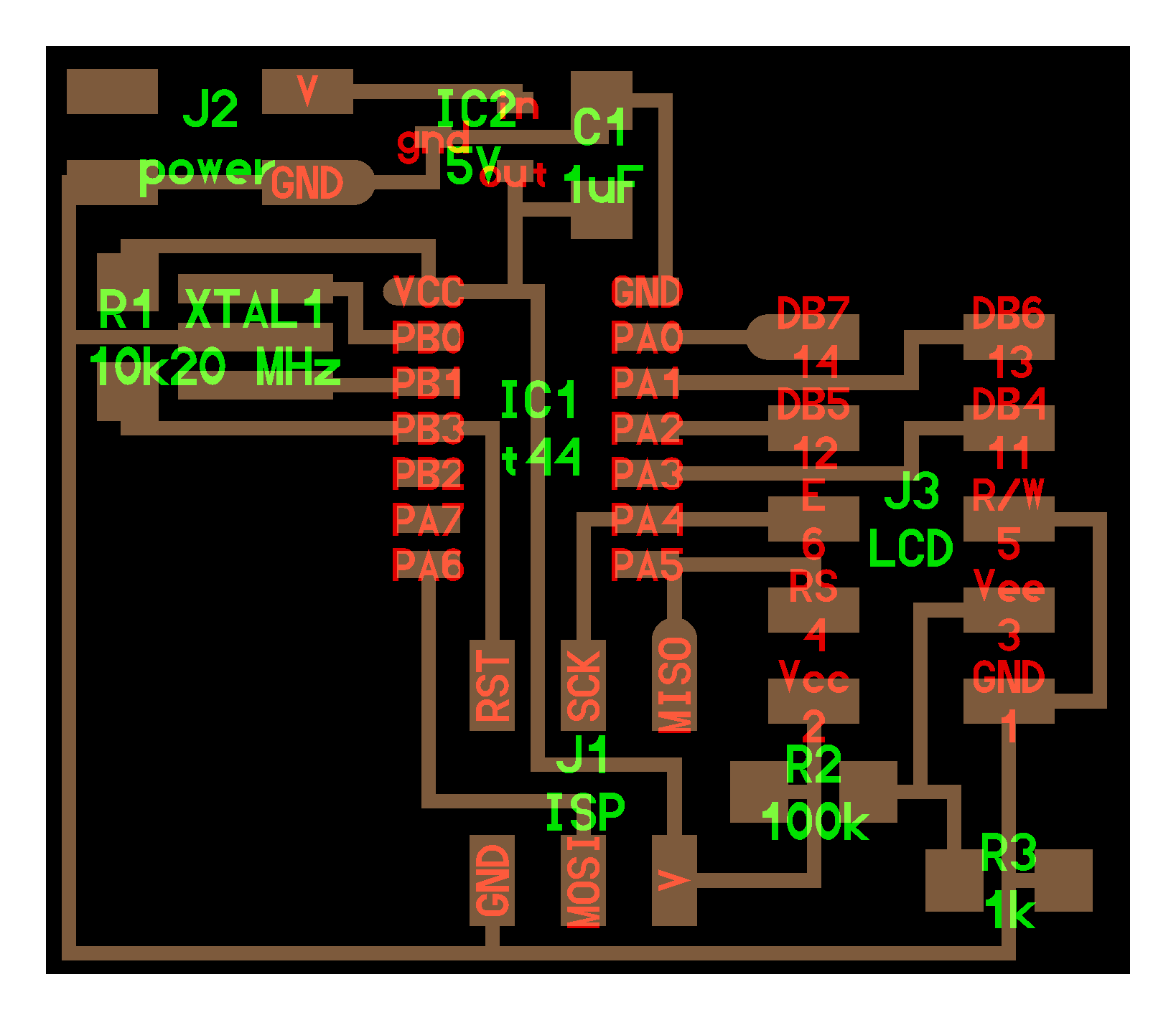
- ATtiny44 microcontroller.
- HD44780 1602 LCD module display (2x16 characters).
- An ISP programmer board (Arduino Uno in this case).
- One 1k and one 100k resistors.
Files to Download
Hero Shot
Group Assignment
For our group assignment about measuring the power consumption of an output device, please click here.
Connecting the LCD to the ATtiny44 Microcontroller
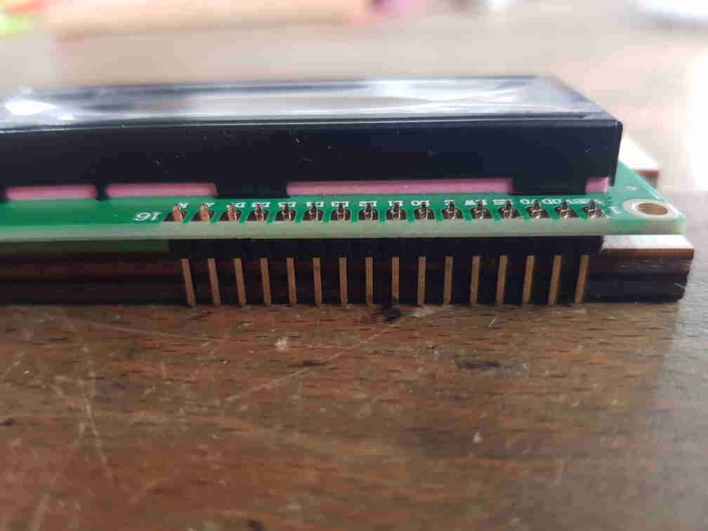
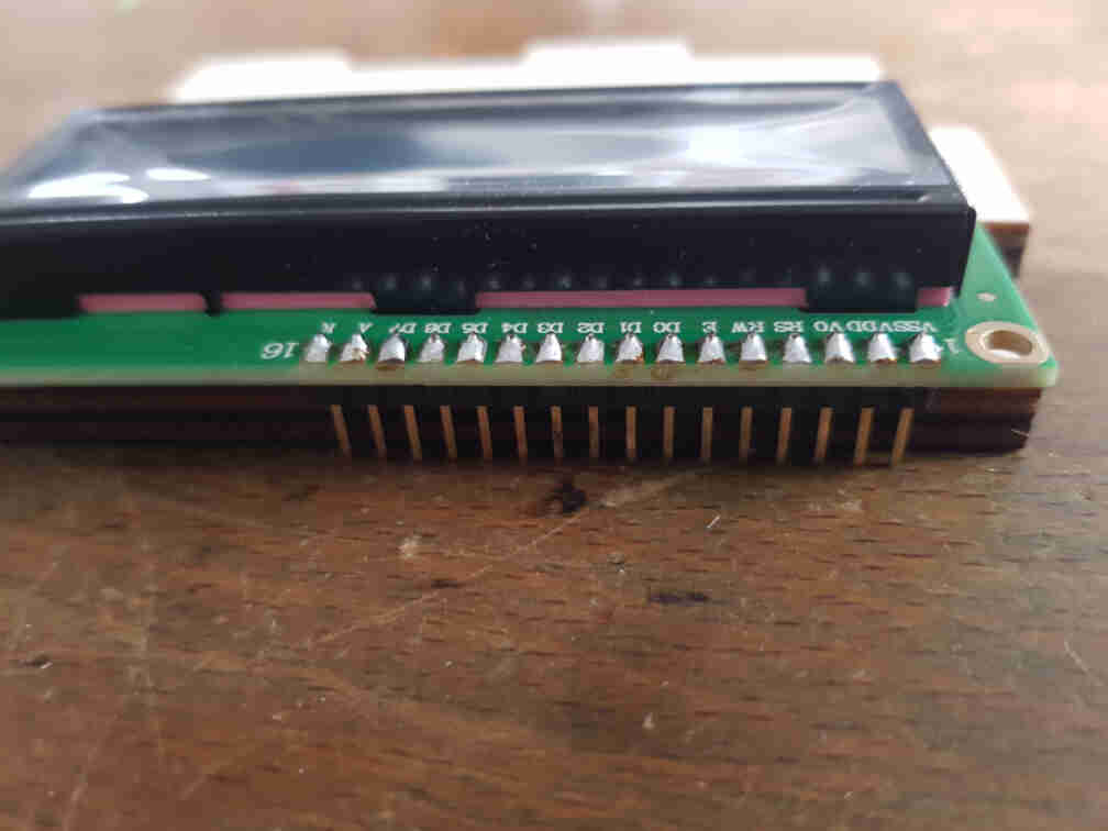
Before I was able to do any programming, I had to attach some pins to the LCD module.
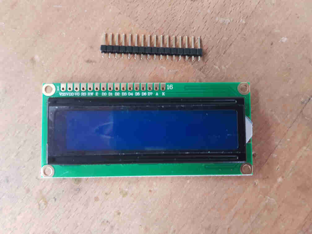
So I went over to the soldering station, propped up the LCD on a piece of scrap wood with the pins in place, and soldered the pins.
I then fired up the datasheet webpage provided by the vendor we got the LCD from, and took a closer look at the module's pinout.
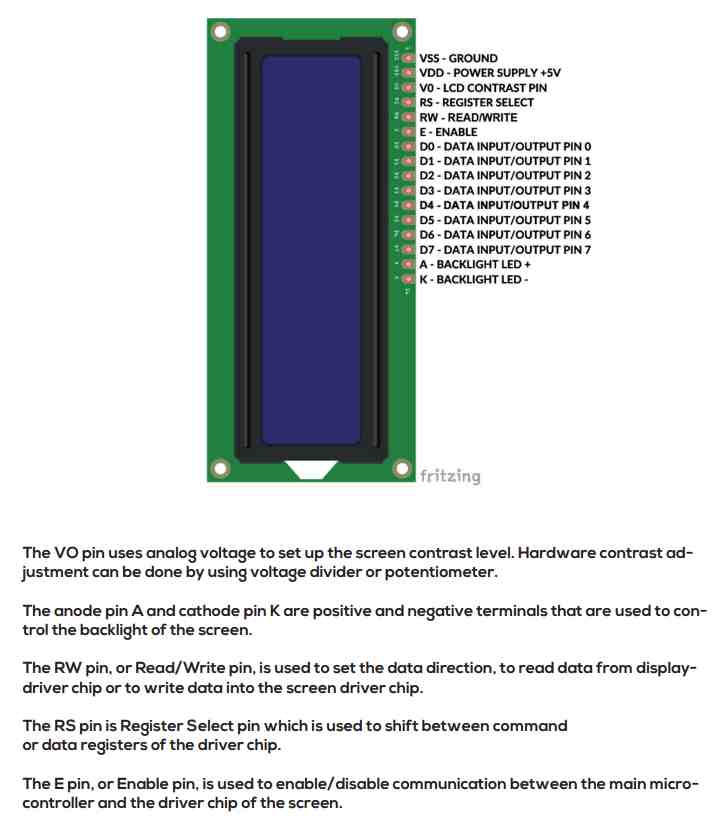
After that I looked up the example circuit on the class webpage to figure out the connections I need to have between the LCD and the Attiny44. And I must admit that I was a bit worried about how to connect the LCD with its 16 pins to the microcontroller, because I thought I did not have enough available pins. But as it turned out, I could make use of only 4 bits instead of the complete 8-bit data input/output pins of the LCD. So I would be using pins D4 to D7.
So going from that diagram, I started connecting jumper wires with the help of a breadboard from the microcontroller to the LCD. In total I had 10 connections to make. I also skipped the two voltage divider resistors that give the V0 a fraction of the 5V supplied and just connected the pin to the arduino 5V pin directly.
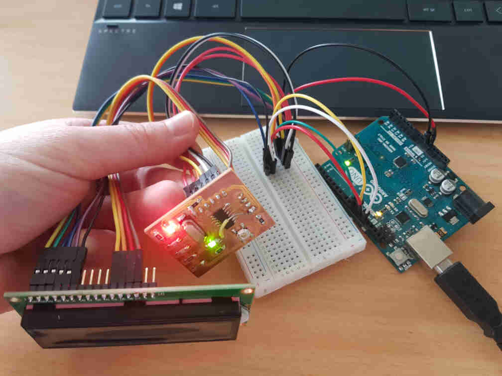
To my disappointment, nothing showed up on the LCD :/. So I went back to the datasheet and realized that I'm not feeding the LCD backlight A and K pins any power, which was probably why it didn't look like it was powered up. I also went an extra step and connected the voltage divider 1k and 100k resistors and attached pin V0 (Vee in Neil Gershenfield's diagram) between them.
I was then ready to connect the arduino to my laptop's USB port to power up the circuit, and was rewarded with some kind of a message the LCD was trying to communicate. I must say that I'm not fluent enough in LCD languages to understand what it wanted.
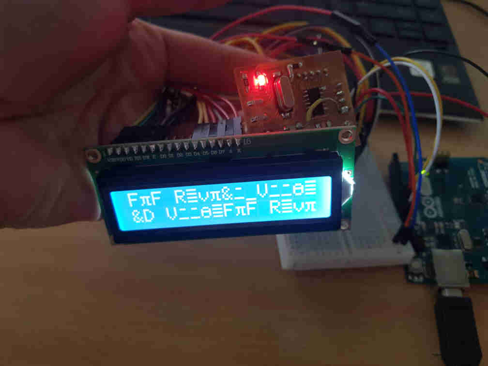
Thinking more about it, I that the LCD was trying to translate whatever state th data pins were in to some kind of characters, which didn't work out very nicely in human language, but the effort was appreciated.
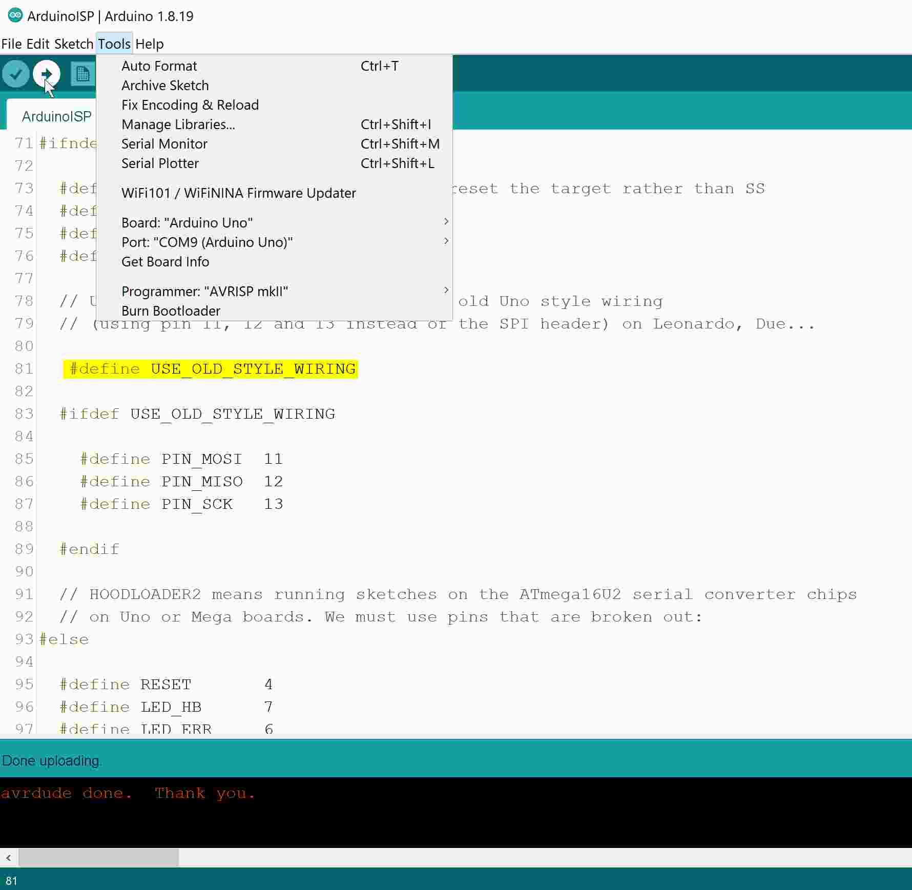
So my next step was to go open the arduino LCD library examples I had once long ago installed, and check out which test code i'd like to run. To do that, I first made sure to program the arduino to be my ISP programmer with the USE_OLD_STYLE_WIRING line uncommented.
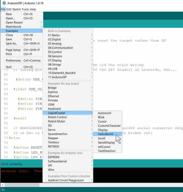
And then tried to run the HelloWorld example.
That, however, did not output anything different from what gibberish I got running on the LCD, although I had made sure to comment the arduino pinout definitions and added the lines:
#define DB7 (1 << PA0)
#define DB6 (1 << PA1)
#define DB5 (1 << PA2)
#define DB4 (1 << PA3)
#define en (1 << PA4)
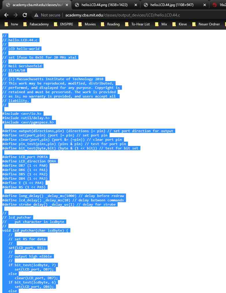
#define rs (1 << PA5)I then decided why not go the extra step and skip the pre-prepared arduino LCD library and try to talk to the LCD in C code instead. So I want back to the class website and copied the example code Neil Gershenfeld had once written, and started reading through it and trying to reverse engineer what was happening in each code block by comparing the code commands with the LCD datasheet.
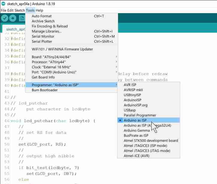
I then changed the IDE settings to be able to program my board.
And ran the code.
And after I thought I understood enough of the code blocks in there, I went down to where the main loop was and edited the code to output a different text other than the HelloWorld sentence.
// main loop
//
while (1) {
//
// go to zero position
//
lcd_putcmd(0);
lcd_putcmd(DB5);
//
// print first line from flash
//
static const char line1[] PROGMEM = "Hi, I'm Leen's";
lcd_putstring((PGM_P) line1);
//
// move to second line
//
lcd_putcmd(DB7+DB6);
lcd_putcmd(0);
//
// print second line from flash
//
static const char line2[] PROGMEM = "code submission";
lcd_putstring((PGM_P) line2);
//
// pause
//
long_delay();
//
// clear display
//
lcd_putcmd(0);
lcd_putcmd(DB4);
lcd_putcmd(0);
lcd_putcmd(DB5);
//
// print first line from flash
//
static const char line3[] PROGMEM = "for the";
lcd_putstring((PGM_P) line3);
//
// move to second line
//
lcd_putcmd(DB7+DB6);
lcd_putcmd(0);
//
// print second line from flash
//
static const char line4[] PROGMEM = "Output Devices";
lcd_putstring((PGM_P) line4);
//
// pause
//
long_delay();
//
// clear display
//
lcd_putcmd(0);
lcd_putcmd(DB4);
lcd_putcmd(0);
lcd_putcmd(DB5);
//
// print first line from flash
//
static const char line5[] PROGMEM = "assignment!";
lcd_putstring((PGM_P) line5);
//
// move to second line
//
lcd_putcmd(DB7+DB6);
lcd_putcmd(0);
//
// print second line from flash
//
static const char line6[] PROGMEM = ":)";
lcd_putstring((PGM_P) line6);
//
// pause
//
long_delay();
//
// clear display
//
lcd_putcmd(0);
lcd_putcmd(DB4);
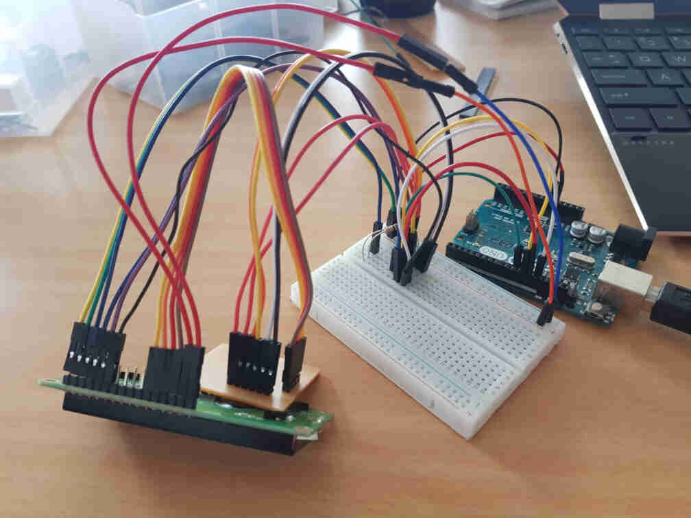
}After that, I want back to my circuit and got rid of all the jumper wires, and connected the microcontroller board pins directly to a small breadboard for easier handling and reconnected the rest of the needed connections with some jumper wires.
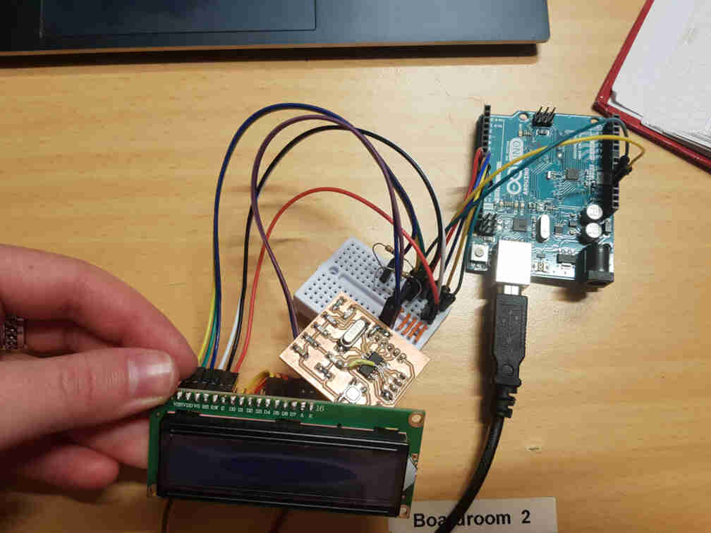
So the connections are as follows:
| Arduino Uno | ATtiny44 | LCD Module |
|---|---|---|
| Pin 5V | Pin 1 (VCC) | Pin VDD, Pin A |
| Pin 10 | Pin 4 (RESET) | - |
| Pin 11 | Pin 7 (MOSI) | - |
| Pin 12 | Pin 8 (MISO) | Pin RS |
| Pin 13 | Pin 9 (SCL) | Pin E |
| Pin GND | Pin 14 (GND) | Pin VSS, Pin K, Pin RW |
| Pin GND + 1k Resistor | Pin 1 (VCC) + 100k Resistor | Pin V0 |
| - | Pin 10 (PA3) | Pin D4 |
| - | Pin 11 (PA2) | Pin D5 |
| - | Pin 12 (PA1) | Pin D6 |
| - | Pin 13 (PA0) | Pin D7 |
And finally ran my code!