
Assignment 4 - Computer Controlled Cutting
Group Assignment
The page for the Group Assignment for the Lab in Kamp-Lintfort can be found here. My individual contributions were the following things:
- The introductory text with images explaining the Epilog Fusion and how to use it.
- The kerf measurements and calculations
- The cutting and showcasing of the different joint types with and without kerf
So from all of this what have I actually learned? For all of the Joint types it is majorly important to have an accurately measured kerf. If the kerf is neglected or measured wrong, the joints will be either too loose or wont fit together at all. SO for my own project I will double and triple check my kerf measurements and will have a second look on the offset I apply. Apart from this I learned many things about Joints in general and found (at least for myself) the simplest Joints to be working the best. While other Joints could be better, some of them are very delicate and therefore quite fragile. More than once, I broke off small parts and had to redo something. This is why I decided on the more "normal" types of joints for my own project.
Individual Assignments
Vinyl Cutting
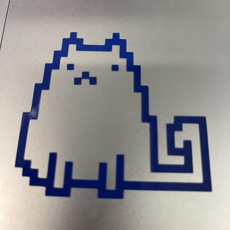
At out local lecture we got introduced to our vinyl cutters of which I just used the smaller Silhouette Portrait to cut vinyl. The first thing I wanted to cut was the pixelated Cat I created as part of last weeks assignment. Before I exported the image from GIMP and imported it into Silhouette Studio to send the image to the printer, I first had to change the Image up quite a bit. Since the vinylcutter should trace the outer and inner lines of the image later on, I thought it would be very bad to just leave the image in the pixelated art style it is now in. When the knife of the machine would cut the inner trace aufter the outer trace, it would only leave single pixels and not a whole image.
So I went ahead and edited the CatStation Logo from last Week to combat the problem from above. After editing the image to get around the aformentioned problem I was left with the follwing result:
Now that the image was ready for use in vinyl cuttig I exported it from GIMP and then inserted the image into Sihlouette Studio. In Sihlouette Studio the user has many different tools at hand to draw directly or to alter and change imported images.
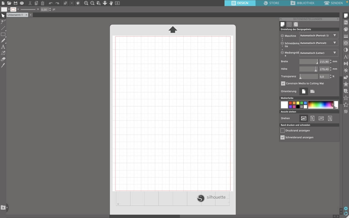
For all the vinyl cutting I did for now, I used the tracing tool. It can be used different ways. The first way would be to trace the image completely and the second way would be to just trace the outlines of the images. I chose the latter option for my Image. So after importing the image into Silhouette Studio, I opened the tracing menu:
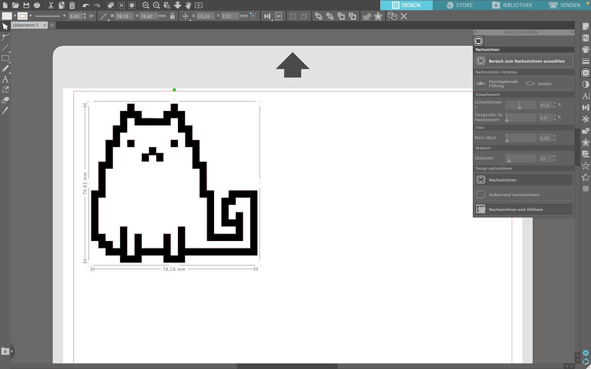
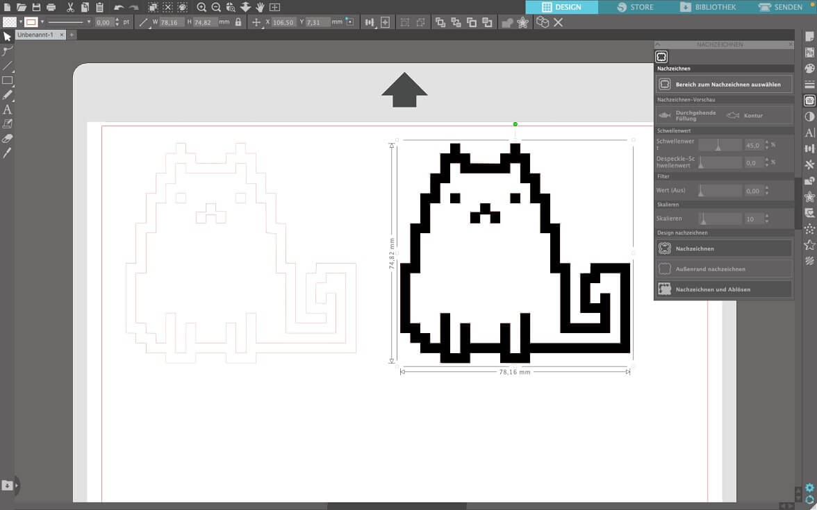
After selecting the option for seperating the lines from the image, i deleted the imported image and was only left with the outlines of the image in Sihlouette Studio:
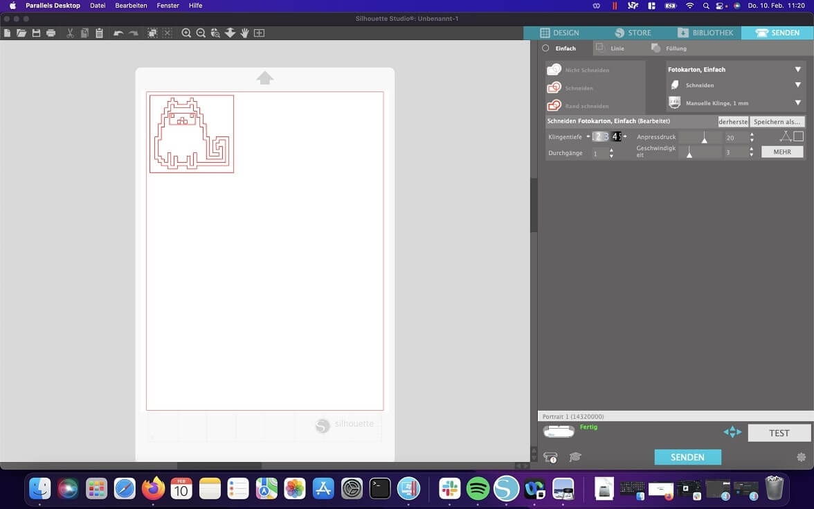
After surrounding the whole outlined Image, as well as the eye and mouth part of the lines with a square, I sent the job to the vinyl cutter:
After the vinyl cutter was done I slowly peeled away everything I did not need and covered everything with masking tape to losen it from its original place and set it all in one part onto the surface I wanted (In this case my Laptop). Sadly the cats mouth and Eyes did not stick all too well to the maskig tape, so I had to apply them manually later on. This all resulted in a pixel cat vinyl sticker now applied to my laptop. In hindsight it would have been better to apply the whole sticker onto the laptop and weed it afterwards. The problem with this was, that I was scared to scratch my laptop and so chose to go the other route of weeding beforehand.
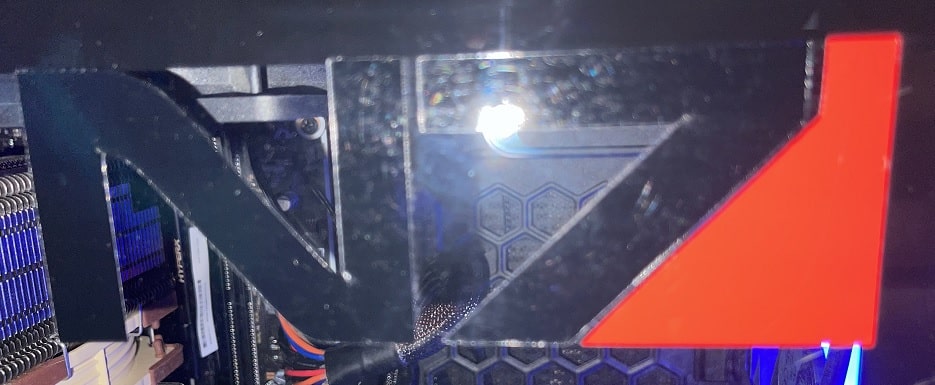
This process went so smooth and made alot of fun. This is why I just could not stop from creating more stickers. I created two Logos (One for me and one for my wife to use) from the video game series Mass Effect. The process was pretty similar to process with the Cat Logo. I searched for the Logo on the web and found downloaded it from here. Since the Logo comes with different colors I had to make two different cuts. So I cut the Logo apart with GIMP so I could use each part seperately. I put the both into Silhouette Studio to scale them correctly but only traced the outline from and cut the balck part first. After that I only traced and cut the red part and after that was presented with the fully cut Logo.
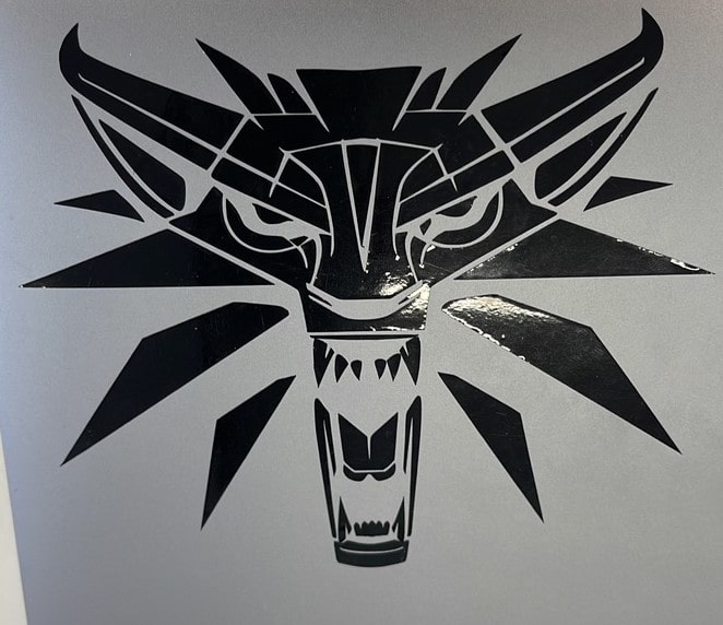
And even after that I created another Video Game Logo to put on my Laptop. This time the wolf from "The Witcher". I downlaoded the following image from here:

This last one was very hard is it consisted of multiple very small parts. I used masking Tape but sadly on multiple occasions the vinyl would have a better fixture with the masking tape than with my Laptop. I peeled the sticker away from the masking tape verty slowly and in the process tried to unstuck every piece of vinyl that did not want to be loosened from the masking Tape. This worked for the most part but this process took nearly half an hour. At the end i just applied the last little pieces of vinyl still sticking to the masking Tape by Hand and was left with this:
Constuction Kit
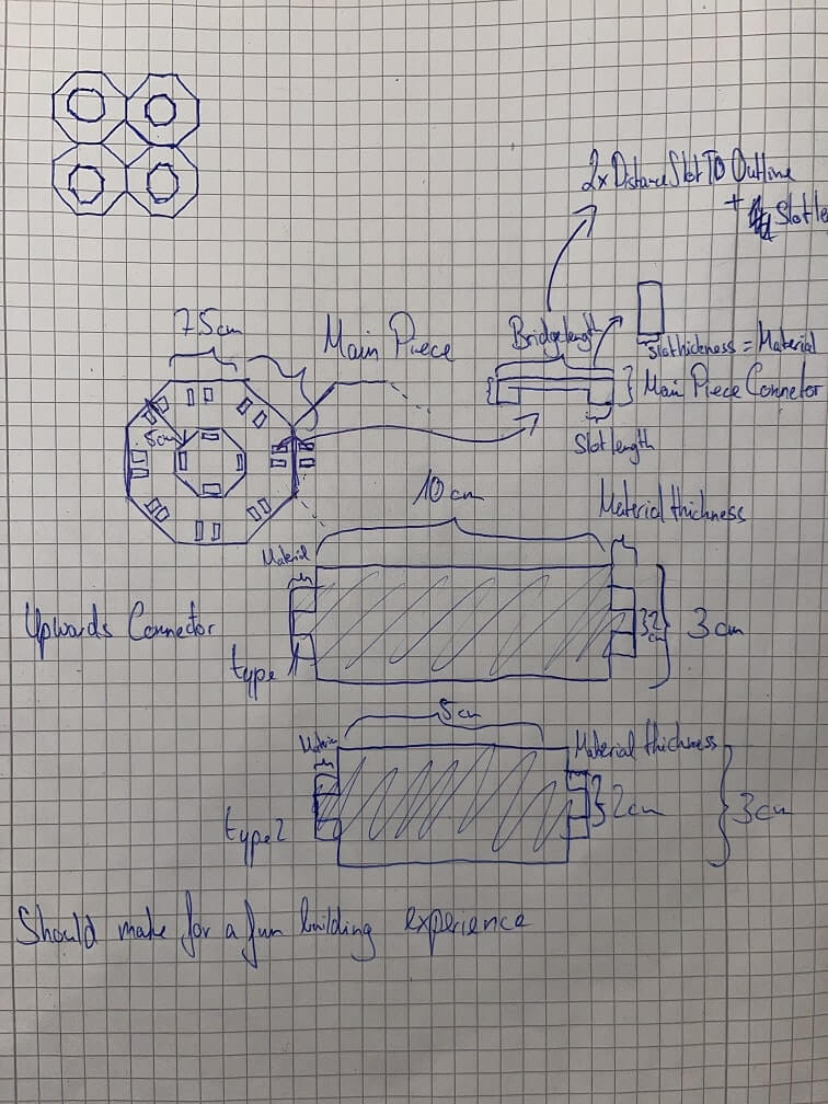
For this assignment I had many ideas that were coming to my head but at the end I stuck with the idea of a construction kit which could be extended along the x- and y-axis as well as the z-axis. My first sketch for this looked like this:
After sketching I began working on the sketches in Fusion360 using parameters I would define on the
way. The first thing I designed was the main ocatgon piece. For this I created an ocatgon with eight
equal sides and with the help of construction lines I created the first two slots on the outside of
the octagon. To save some time and have everything alligned perfectly I now used the option
Create > Circular Pattern within the sketch and chose the two slots I created as
objects to multiply as well as the center of the shape as the point to revolve around. This worked
very good and ensured that all the slots are at the same place on each side of the ocatgon. After
the outer slots were done I created the inner ones. I offset the whole outer shape to create a
smaller octagon on the inside, so that I could reference it for the inner slots. I used the same
process for the inner slots as for the outer slots.
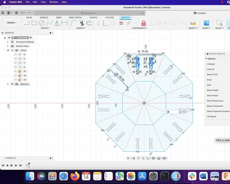
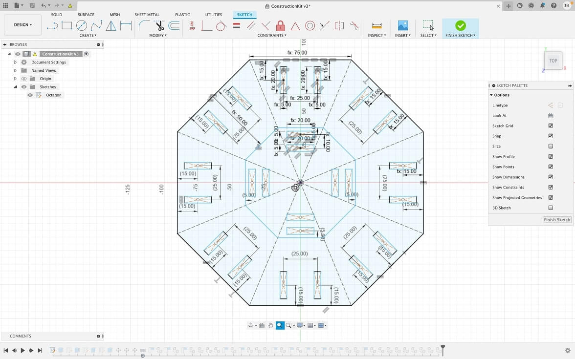
Looking at the sketch in Fusion360 and then again at the sketch I drew at the beginning, I noticed that it was only possible to build up once, as the slots for building up further would then be occupied by by the connectors comming from below. This is why I changed the sketch to allow for building up further by creating a second set of clots in the inner area of the octagon, resulting in this octagon as the final shape:
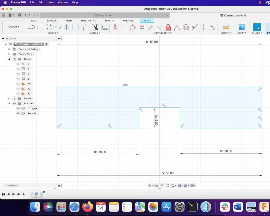
After the octagon I sketched out the bridge element to connect two octagons on the x/y-axis. For this I calculated the length this part should have based on the distance of the slot to the outer edge and the slots length and saved this calculation as a paramter. The rest of the shape was quickly done:
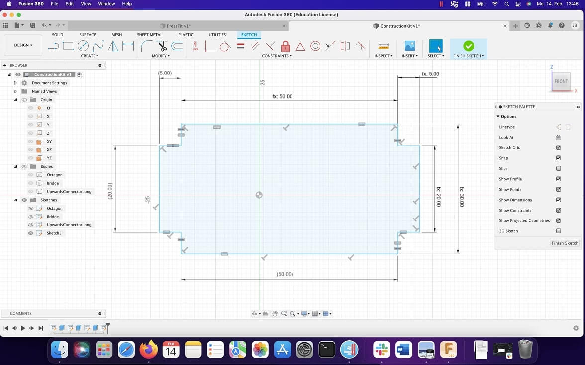
With the bridge element done, the connectivity of the pieces was done on the xy-axis. Since I wanted to create something that could be built in the z-axis as well, i now created both a hort and long version of the connector that would allow two octagons to be placed above each other. For the parameters on these I defined two lengths (one for each type of connector). The rest of the parameters for the connectors were already there. After sketching them both out, these were the two sketches I finished on:

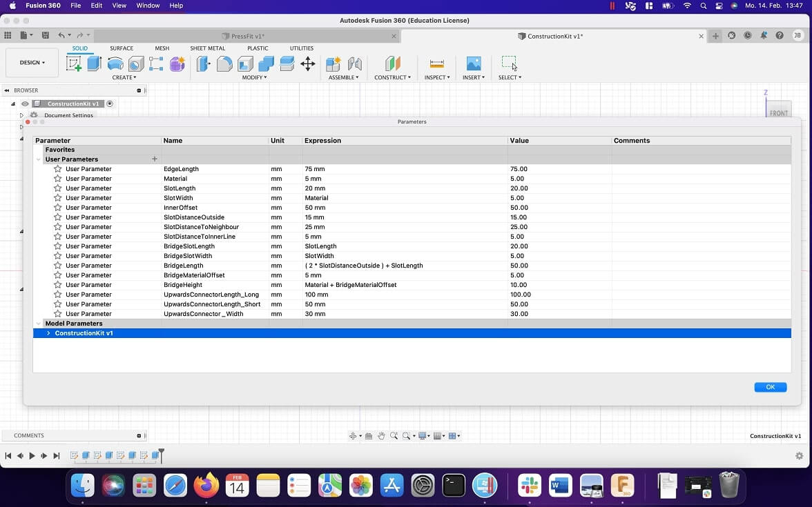
At the end of all sketches I had the following list of parameters:
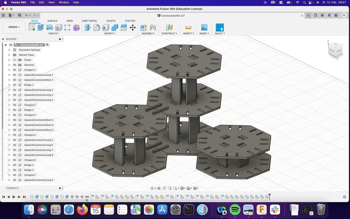
After sketching out all the parts i started creating components and alligning them in Fusion360 to have a look if what I had in mind was even working. So after alligning multiple different components I created something like this:
Sadly at this point I had not much time to do something in the lab, so I hurried and set the kerf
offset for all models and went on to cut them all on the laser cutter. To cut the sketches, I
exported them one after another and opened them within Rhino, which is the software we are using at
the lab to send the jobs to the laser cutters. For some of the sketches somehow the constrcution
lines were also exported, so i had to delete them manually from the imported files in Rhino. After
grouping the lines of the imported file together and checking the scale of the imported model, I set
the cutting width to
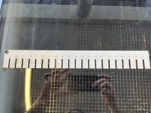
I also havent taken an Image of the cutting process, So I can just share this Image from our Group Page, where I just cut the kerf test part:
I took all the cut parts and built the structure the next day at home. As you will see, i sadly did not find a bigger sheet of material in the hurry I was in, so I was just left with two octagons, a few bridge pieces and a whole set of short upwards connectors. To give you an example of what could be possible with these laser cut parts, I quickly threw together both octagons, once on the xy-axis and once on the z-axis:
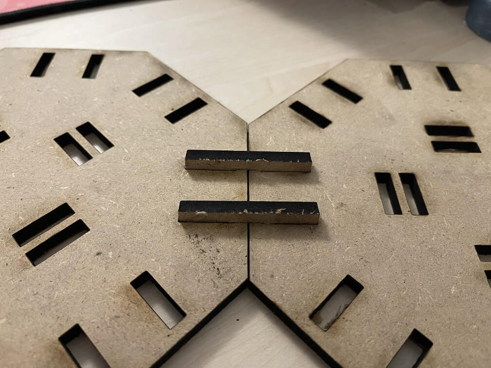
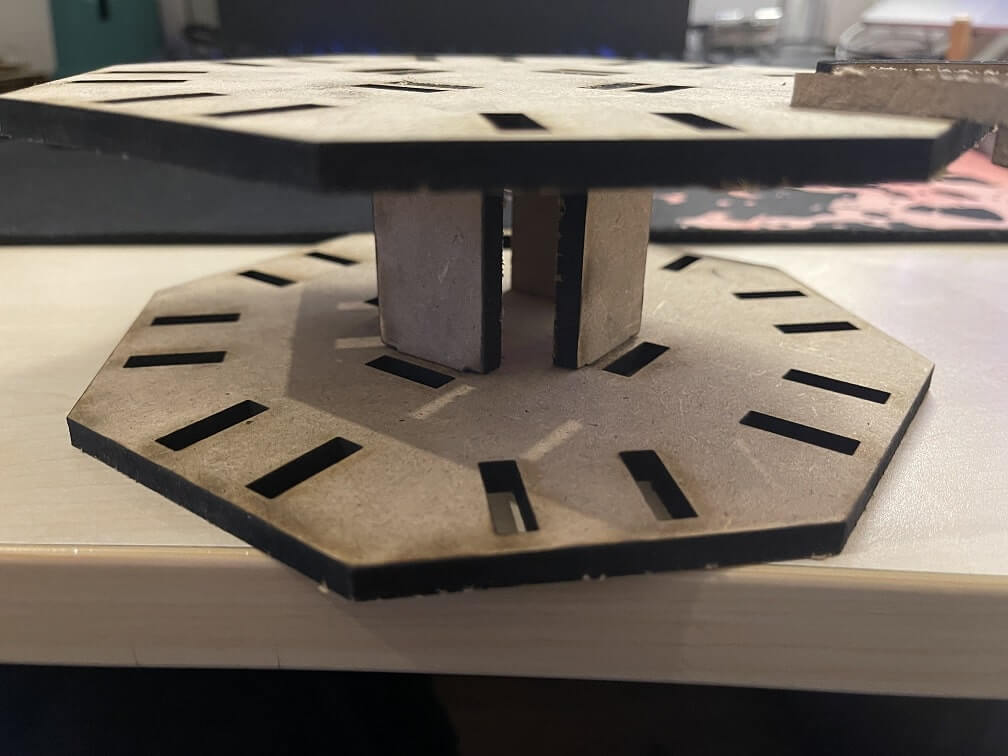
As you can see, the cuts werent perfect, but everything fits together very nice and tight. I will try to cut some more pieces in the future and post one last image with a few more pieces stuck together on this page.
Final Thoughts
I sadly did not have enough time this week to finish the construction kit to my liking. As it is now its more like a proof of concept. Vinyl Cutting and Lasercutting are very fun though and I think to finish the construction kit assignment better, I shouldnt have made so many things with the vinyl cutter. But in the end I did create something you can use/touch for vinyl cutting and for laser cutting, so all in all I am still satisfied with my weekly work. As opposed to last week I did not have any major setbacks this week. Fusion worked like a charme and Silhouette Studio also was very intuitive to use. It was quite satisfying to use the laser cutter with models that used the kerf offset. The parts are simply so much tighter and far more secure together.
File Downloads
- Construction Kit Fusion360 Project
- Construction Kit Octagon DXF
- Construction Kit Bridge DXF
- Construction Kit ConnectorLong DXF
- Construction Kit ConnectorShort DXF
- Cat Sticker SVG
- I wont upload the Game stuff, since its under copyright. The files are readily available online though and can be prepared just like I showcase above!